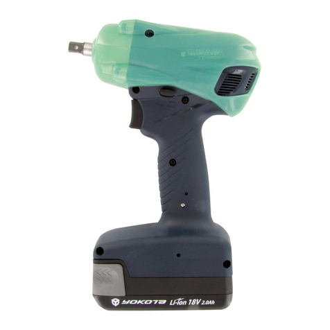
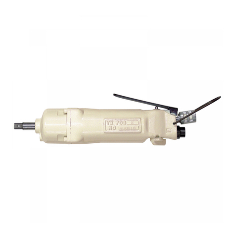
Yokota YS-e600 User manual

YS-e Instruction Manual 76-QD0444EN-00Y01-00.doc
1
Battery system wrenches with built-in angle sensor
YS-e600
YS-e800
YS-e900
YS-e950
Instruction Manual
Thank you for purchasing YOKOTA products.
Before use, please read this Instruction Manual carefully and use the product
properly after fully understanding the Manual.
Please be sure to keep this Instruction Manual.
YOKOTA INDUSTRIAL CO., LTD
Head Office/Factory 5-55 Nishiiwata 3-chome, Higashiosaka City, 578-0947 Osaka, Japan
TEL.: +81-6-6788-1381 FAX. +81-6-6781-4519
http://www.yokota-kogyo.co.jp

YS-e Instruction Manual 76-QD0444EN-00Y01-00.doc
2
Table of contents
1. SAFETY CARE ....................................................................................................................... 3
2. SPECIFICATION .................................................................................................................. 10
3. EACH PART DESCRIPTION ................................................................................................. 12
4. REPARATIONS BEFORE USE ............................................................................................. 14
5. PAIRING ............................................................................................................................... 15
6. SINGLE OPERATION MODE ................................................................................................ 17
7. FUNCTIONS OF THROTTLE LEVER AND REVERSE LEVER ............................................ 18
8. METHOD OF ADJUSTMENT OF OUTPUT ........................................................................... 18
9. ACCESSORIES .................................................................................................................... 19
10. BUZZER SOUNDS AND LED LIGHTING PATTERNS ........................................................... 20
11. TROUBLESHOOTING .......................................................................................................... 22

YS-e Instruction Manual 76-QD0444EN-00Y01-00.doc
3
1. Safety Care
Warning
Please be sure to thoroughly read this Operation Manual and fully understand the instruction to use
correctly, before installation, operation and inspection.
In this Instruction Manual, safety precautions prefix either of the following safety alert pictograms.
All are important items relating to safety and must be observed.
Warning・・・ Cases where mishandling induces a potentially hazardous situation, which, if not
avoided, could result in a death or serious personal inquiry.
Caution・・・ Cases where mishandling induces a potentially hazardous situation, which, if not
avoided, may result in minor or moderate personal injury or property damage.
※Notes: Even items described in “ Caution” may lead to serious consequences depending on
circumstances.
・Retain this instruction Manual in a place where it is always available for anyone who needs to use it.
・In cases where you lost this Instruction Manual or the warning label affixed to the product or made it dirty,
immediately contact us or your YOKOTA representative to obtain the Manual or the warning label, and
then properly retain the Manual or replace the warning label.
・In cases where you transfer or rent this product, be sure to attach this Instruction Manual to it.
・If you have any questions on the product or the contents in this manual, please contact us or your sales
outlet where you purchased the product.
1.1. Working Environment
Warning
・Ensure that the workplace is sufficiently light.
Working in a dark place may result in accident or injury.
・Do not operate the tool and charge the battery in explosive atmospheres, such as in the presence of
flammable liquids, gases or dusts.
There is fear of fire.
・Keep anyone, particularly children, other than those involved in the work away from the work site.
Not doing so could induce a hazardous situation.
Otherwise, it may cause injury.
・Take drop preventive measures such as use of safety wire to work in high places. Also be careful for the
falling-off accident, by confirming surely the safety of scaffolding.

YS-e Instruction Manual 76-QD0444EN-00Y01-00.doc
4
・【Noise might be regulated under laws and regulations of the country or regions where the product is
used.】
The tool must be used at noise levels below those prescribed by them. Install sound insulation walls,
depending on the necessity.
If noise levels at the operator’s position exceed 85dB (A), be sure to use earplugs. Even if noise levels
are not more than 85dB (A), it is recommended to use earplugs.
・Do not install this product in a place likely to be exposed to water, direct sunlight, much dust, heat, oil, or
moving parts of industrial equipment. Otherwise, it may cause fire, electric shock, or accident.
1.2. Electrical Safety
Warning
・This product is for the indoor exclusive use. Do not use it in rain, in a damp place and a wet place.
Moreover, never use it in the place with the fear of the ignition and the explosion, because those are
hazardous situation.
・Do not hold the power supply cord for battery charger for carrying or pull the cord to unplug it. In addition,
be careful to avoid stepping on or being caught by the cord, and/or damage by excessive force. Damage
of the power supply cord may result in accident.
・Do not insert the power supply cord of the battery charger between the objects to be tightened or contact
it with rotating parts. Otherwise, it may be damaged and cause accident.
・ Use the exclusive battery pack and battery charger only.
Failure to do so may result in rupture of it and damage of the product or property.
・Use the battery charger at rated supply voltage (AC 100-240 V).
Do not use DC power supply, engine generator, or power transformer. Failure to do so may result in heat
generation and fire.
・Do not disassemble or modify the battery pack and battery charger.
Doing so may result in heat generation, fire, electric shock, or injury.
・Do not throw the battery pack into fire or heat it.
Doing so may result in rupture or release of hazardous substances.
・Do not drive a nail or give an impact such as fall on the battery pack or battery charger.
Doing so may result in heat generation, fire, electric shock, and/or injury.
・Do not short-circuit the terminals of the battery pack.
Do not carry or store the battery pack with metal object such as nail. Doing so may result in smoking,
ignition, or rupture.
・If the battery pack gets hot during its use, stop using it immediately and contact your sales outlet or sales
agent.
・If the battery pack leaks, stop using it and contact your sales outlet or sales agent.
・Be sure to fully insert the power plug of the battery charger.
Failure to do so may result in electric shock or fire due to heat generation.

YS-e Instruction Manual 76-QD0444EN-00Y01-00.doc
5
・If you do not use the product, unplug the battery charger.
Wipe out dust or stain accumulated on the power plug or receptacle with a dry cloth. Failure to do so may
result in electric shock or fire.
・Do not insert or remove the power plug of the battery charger from the receptacle with wet hand.
Doing so may result in electric shock.
・Charge the battery pack in well-ventilated place. While charging, do not cover the ventilation openings on
the battery pack and battery charger with cloth. Doing so may result in rupture or fire.
・Do not charge the battery pack at less than 0℃ or more than 40℃. Doing so may result in rupture or fire.
・Do not store the battery pack in a place reaching over 50℃. Doing so may cause deterioration of the
battery pack and result in smoking or fire.
・Attach an anti-short-circuit cap after the battery pack is removed from the tool or the battery charger or
when the tool is not used. Failure to do so may result in short-circuit of the terminals of the battery pack
and fire.
1.3. Human Safety
Warning
・Do not use the tool when you are tired or under influence of drugs, alcohol or medication.
A moment of inattention during the use of tool may result in serious personal injury.
・To protect yourself, wear personal protective equipment such as a hard hat(helmet), safety glasses,
safety shoes.
And depending on work environment, wear earplugs, a dust mask etc.
・ Before doing the following actions, make sure that the throttle lever is at stop position. Otherwise, the
tool may accidentally operate and it may result in injury.
・Torque adjustment
・Replacement of socket and bit
・Insertion of the battery pack
・Other cases in which the operation of the tool may result in danger.
・If carry the tool, do not put your hand on the throttle Lever.
Otherwise, the tool may accidentally operate and it may result in injury.
・Before attachment of the battery pack to the tool, make sure that the tools such as spanner used for fixing
the accessory, pins used for capability adjustment are removed.
・Working in unusual positions is dangerous. Hold the tool securely and carry out working in stable posture,
preparing for accidental movement at the same time.
・Dress properly. When working, do not wear loose clothes or jewellery such as necklace. If your hairs are
long, bundle them with rubber ring to avoid contact with the tool and wear a protective cover such as
cap. Otherwise, it may cause injury.
・If the electrolyte of the battery gets in your eyes, do not pass your hand over your eyes, but flush them
with a plenty of clean water and seek medical attention. Failure to do so may result in loss of vision.

YS-e Instruction Manual 76-QD0444EN-00Y01-00.doc
6
・If the electrolyte of the battery comes in contact with body part or clothes, rinse with a plenty of clean
water and seek medical attention. Failure to do so may result in dermal inflammation or injury.
1.4. Operation and Care
Warning
・Use the electric tool within its capacity. Unreasonable use of the tool in overload could result in the
damage or failure of the tool.
・Use the tool with proper tightening capability for the object to be tightened. If the capability is too big for
the object, the object may be broken or damaged and the broken pieces may cause injury. If the tool is
repelled when it is broken or damaged, your hand or arm may hit the surrounding object and you may
get injured.
・Use the power tool for tightening of screws. Use for other purposes may cause accident.
・If attachments for hand tools are used, there is a risk of breakage which may cause the accident such as
scattering of fragments. Therefore be sure to use attachments for power tools.
・After installation of the attachment, pull it lightly and make sure that it does not come off. In case of
dropping in error or application of external force to power tool, check the installation condition of the
attachment again. Note that unsecure installation may cause damage on the attachment and/or early
malfunction of the product as well as accidents.
・Use socket stoppers specified by Yokota or socket makers. Do not use wire, a nail and others as a
substitute for a socket stopper, which can cause serious accidents.
・Use socket stoppers specified by Yokota or socket makers. Do not use wire, a nail and others as a
substitute for a socket stopper, which can cause serious accidents.
Do not use the bit or socket with large mass(heavy or long). Such mass may be transferred as the false
torque to the tool, which may cause the incorrect tightening.
・Before operation, be sure to carry out precheck for the following. If you fail to do it, it may cause not only
degradation of performance or trouble but also danger.
・No loosening or damage of screws for the tool
・No problem on operation of throttle lever or reverse lever
・No abrasion or damage on the accessary, etc.
・Normal room/play for the connection between the tool and socket or between the tool and
battery pack, etc.
・If the tool does not start or stop by the throttle operation, stop using the tool immediately.
Then ask repair and inspection to YOKOTA or YOKOTA-authorized or designated servicing factory via
the sales outlet or sales representative. If any accident or problem occurs due to the customer’s
intended action such as disassembly of this product, we shall not be liable for such trouble.
・Avoid the use of the power tool by persons inexperienced for handling. Otherwise, it may result in injury
and/or accident.

YS-e Instruction Manual 76-QD0444EN-00Y01-00.doc
7
・Handle the power tool carefully. Abuse may cause accident and/or malfunction. Do not give impacts on it
by throwing or dropping it.
・Do not make the foreign object such as metal pieces, invaded to the product. There is fear of fire.
・Fix the work piece (object to be tightened) securely. If the fixing is insufficient, the work piece (object to
be tightened) may be dispersed and it may cause injury.
・Put the attachment securely on the tool before pulling the throttle lever.
・NEVER bring your hand or a cloth and so on to the moving part of the tool.
・Take a break as appropriate. Continuous and long work may cause diseases.
・If you feel problem continuously or intermittently such as numbness, sting, pain, chlorosis, burning
sensation, stiffness, inform the responsible manager in charge and get the doctor’s diagnosis.
・NEVER make any modification to the tool. Doing so could result in accidents. In addition, never use the
spare part other than the genuine one.
・Do not remove the parts from the tool. If you use such tool as the mounted parts or screws removed, it
may cause accident.
・Keep the tool away from the moving parts of plant facility. Otherwise, the tool may be entangled or
pinched and it may be damaged.
・When the tool is damaged, stop using it immediately. In addition, to avoid the use of the damaged tool,
identify it as damaged and separate it from normal ones.
・If you feel uneasiness during the use, stop using the tool immediately and ask repair and inspection to
YOKOTA or YOKOTA-authorized or designated servicing factory via the sales outlet or sales
representative. If any accident or problem occurs due to the customer’s intended action such as
disassembly of this product, we shall not be liable for such trouble.
・Be sure to check the direction of reverse lever of the power tool before operation. Be sure to switch the
rotational direction while the power tool stops.
・Pull the throttle lever of the tool slowly to start. Sudden start may cause accident or malfunction.
・Engage the socket or bit securely into the bolt and nut.
If the socket comes off from the bolt, during the operation, it is very dangerous.
・Hold the tool securely to be prepared for the reaction force. Reaction force may push you around when
tightening.
・When running the tool at no load, be sure that the tip tool (like socket, bit and so on) was removed without
fail and be careful around the surroundings. The operation at no load for a long time will cause the part
breakdown with seizure, early wear and so on.
・Be careful about burn injury. Immediately right after tightening, metal parts, accessary, bolts and nuts
may be hot.
・Do not stick the pin, bar and so on into the inlet and exhaust of the cooling fan nor plug the hole.
YS-e Instruction Manual 76-QD0444EN-00Y01-00.doc
8
・Before doing the following actions, remove the battery pack from the tool. Otherwise, it may accidentally
operate and result in injury.
・Storage or repair of the tool
・Replacement of socket and bit
・Other cases in which the operation of the tool may result in danger.
・Store the product in the dry area, where children or untrained person can not get access to. It is
dangerous for the untrained person to use it.
・Confirm the torque periodically by the torque wrench after tightening the bolt, nut and so on.
Caution
・If the tool is suspended by balancer, etc., mount the hanger on the tool according to “Accessories”
shown below.
Mount YOKOTA-specified parts for hangers.
Use the mounting holes for hanger only for mounting YOKOTA-specified parts.
・Make sure that hooking parts such as balancer are reliably mounted on hanger of this product. Check, at
a regular interval, .the following inspections on:
・ No damage of hooking parts such as balancer, and correct mounting condition.
・ No damage on hanger.
1.5. Maintenance, Inspection, and Repair
Warning
・Before maintenance, inspedtion, and replacement, remove the battery pack.
・Only qualified service personnel are allowed to do maintenance and repair the tool. Repair or
maintenance performed by non-qualified personnel may result in serious personal injury of the user.
・Wipe out the dirt on the housing of the tool by using the dry and soft cloth.
Do not use the chlorinated solvent, gasoline, thinners and the like, which work to melt the plastic.
・Ask repair and inspection to YOKOTA or YOKOTA-authorized or designated servicing factory via the
sales outlet or sales representative where you bought the product. If any accident or problem occurs due
to the customer’s intended action such as disassembly of this product, we shall not be liable for such
trouble.
・If the battery pack or the battery charger is damaged, be sure to ask us or our qualified (designated)
servicing factory to replace or repair it via your sales outlet or sales agent.

YS-e Instruction Manual 76-QD0444EN-00Y01-00.doc
9
1.6. Other Cautions
Caution
・Use protector only specified by YOKOTA for prevention of wounds.
・Do not touch the oil plug of the tool except repairing. It causes early oil leakage.
・Using a tool which has been in storage for more than 6 months may cause oil leakage because of
damage to the seal part on the impulse mechanism.
We will overhaul the new tool which has been in storage for more than 6 months, for free of charge.
・When using in cold place or in winter season, warming up for the power tool is required. Operate the tool
for about one to two seconds several times by loading the main shaft. If the warming up is not carried
out, slip phenomenon may occur. (pulses may not generate.).
・In cold location or before starting the work in winter season, use fully charged battery pack.
If the battery pack is at low level, it may not be able to be used due to its protective function.
・If the tool operates for approximately half of work rate with fully charged battery pack, it means the
expiry of its operating life. Buy a new battery pack.
・If the tool is not used for long time, fully charge the battery pack before storage.
Even during storage, fully charge the battery pack at least once within one year of last charge.
Otherwise, over-discharge of the battery pack may prevent it from charging.
・Lithium-ion battery used in this battery pack is recyclable and valuable resource.
If it is no longer used, bring it to your sales outlet, etc.

YS-e Instruction Manual 76-QD0444EN-00Y01-00.doc
10
2. Specification
・Tool
Model YS-e600 YS-e600A YS-e800 YS-e800A YS-e900 YS-e950
Suitable size of screw M6 M6 M6~M8 M6~M8 M8~M10 M10
Torque adjustment range (*1) 7 to 20Nm 5 to 18Nm 15 to 35Nm 10 to 30Nm 30 to 50Nm 40 to 60Nm
Weight
incl. battery pack 1.75kg 1.75kg 1.80kg 1.90kg 1.90kg 1.94kg
excl. battery pack 1.34kg 1.34kg 1.39kg 1.49kg 1.49kg 1.53kg
Max. rotation speed at no load 4800rpm 4800rpm 4800rpm 4800rpm 4800rpm 4800rpm
Total length 214mm 214mm 219mm 219mm 226mm 226mm
Total height 244mm 244mm 244mm 244mm 244mm 244mm
Distance from the center of
spindle to outer diameter 32.5mm 32.5mm 32.5mm 32.5mm 32.5mm 32.5mm
Dimension of square drive 9.5mm Hex6.35 9.5mm Hex6.35 9.5mm 9.5mm
No. of tightened pieces/min.
*2 10 pcs./min. 10 pcs./min. 8 pcs./min. 8 pcs./min. 6 pcs./min. 5 pcs./min.
Tightened pieces/charge *2 1300 pcs.
/charge
1300 pcs.
/charge
800 pcs.
/charge
800 pcs.
/charge
700 pcs.
/charge
650pcs.
/charge
Noise
<EN60745-2-2>
Sound
pressure
level LPA
72dB 72dB 76dB 78dB 78dB 78dB
Uncertainty
KPA 3dB 3dB 3dB 3dB 3dB 3dB
Total of values for three
measured axes of vibration
<EN60745-2-2> *3
<2.5m/s2> <2.5m/s2><2.5m/s2><2.5m/s2><2.5m/s2><2.5m/s2>
Ambient operating
temperature
0 to 40℃
Ambient operating humidity 35 to 80%RH (no condensation) 0 to 40℃
*1: Max. value of each adjustment range is that in hard joint.
*2: The value when the work is tightened at tightening time of 0.5s and ambient temperature of 30 ℃.
It varies with the condition of the work or operating environment and should be used as a guide.
*3:Triaxial combined vibration value was measured according to the standard EN 60745-2-2 and no
value is measured in actual field. This value should be used as a reference for the management of
daily exposure to vibration.
Daily exposure to vibration A (8) is exposure to vibration per day, and it can be calculated from the
following formula with triaxial combined vibration value “a” [m/s2] of the tool and the period of
exposure to vibration per day “T” [h].
(T [time] is not the time for engaging whole corresponding work but the time for actually working with the tool held)
Len
g
th
Height
T
Exposure to vibration per day A(8)=a× ― [m/s2]
8

YS-e Instruction Manual 76-QD0444EN-00Y01-00.doc
11
・Battery Pack
Model BPL-1820
Nominal voltage 18V
Rated capacity 2.0Ah
External dimensions 76mm(W) × 119mm (D) × 45mm(H)
Weight 0.41kg
Ambient operating temperature 0~40℃
・Battery Charger
Model BC0075G
Rated input voltage AC100~240V±10% 50/60Hz
Rated charging current 2A *1
External dimensions 200mm(W) × 130mm(D) × 84mm(H)
Weight 0.84kg
Recharge time
80% charged : 60 min
Fully charged : 70 min
Ambient operating temperature 0~40℃
*1:At rapid charging

YS-e Instruction Manual 76-QD0444EN-00Y01-00.doc
12
3. Each part description
・Tool
① Throttle lever Lever to start or stop the rotation of the main shaft of the tool.
② Reverse lever
Lever to switch the rotation direction (right/left) of the main shaft of
the tool.
③ OK/NG LED
LED to inform the worker of tightening OK, occurrence of error, etc.
(do not stare into LED light for long time)
④ Buzzer (built-in)
Buzzer to inform the worker of tightening OK, occurrence of error,
etc.
⑤ Pairing button (built-in) Button to do pairing with the wireless unit.
⑥ Cooling fan (built-in) Fan to cool motor section and pulse unit.
⑦ Air intake of cooling fan Air intake of cooling fan.
⑧ Exhaust outlet of cooling fan
Exhaust outlet of cooling fan.
Also used as insertion opening for torque adjustment pin.
⑨ Battery pack Detachable battery pack for driving the tool.
●Descriptions of symbols
:Be sure to read this Manual before use and use the product correctly after you fully understand
its contents.
②
③
④
⑤
⑥
⑦
⑧
⑨
①

YS-e Instruction Manual 76-QD0444EN-00Y01-00.doc
13
・Battery Pack
① Terminal part Terminal for connection with the tool.
② Ventilation opening Air intake for cooling the inside of the battery pack during charging.
③ Battery level indicator lamp When PUSH button is pressed, the LED(s) light up and indicate the
level of the battery pack.
<<Guide for battery level>>
3 LEDs lighting: Not less than 75%
2 LEDs lighting: 30 to 75%
One LED lighting: 5 to 30% (charge the battery pack as soon as
possible)
④ Anti-short-circuit cap Cap to prevent from short-circuit of terminal parts.
⑤ Release button Button to release the battery pack from the tool.
・Battery Charger
① Indicator lamp LED lamp indicating the charging level.
② Ventilation openings Openings for cooling the battery pack.
③ Power supply cord
③ ④
①
② ③
②
⑤
①

YS-e Instruction Manual 76-QD0444EN-00Y01-00.doc
14
4. reparations before use
Since the battery pack you purchased is not fully charged, fully charge it before use.
4.1. Before charging
Place the battery charger in a location at 0 to 40℃.
The cooling fan in the charger operates or stops depending on the temperature of the
battery pack.
During the charging, the operation of the cooling fan changes, but it is not a malfunction.
4.2. Method of charging
4.2.1. Connect the battery charger to the power supply cord, and insert the power plug into
the receptacle.
The LED of the charger is still off.
4.2.2. Insert the battery pack into the battery charger.
Slide the battery pack to the end along with the insertion slot of the battery charger.
When it is correctly installed, the LED lights in red and the charging starts.
When the charging is completed, the LED lights in green.
4.2.3. Remove the battery pack from the battery charger.
4.2.4. Remove the power plug of the battery charger from the receptacle.
4.3. Descriptions of indicator lamp of the battery charger
4.4. Installation of the battery pack
Slide the battery pack along the insertion slot of the tool to the end and make sure that it does
not come off (it clicks when the battery pack is slid to the end).
4.5. Removal of the battery pack
While pressing the eject buttons on both sides of the battery pack, slide it to your side.
Color
OFF OFF Condition of plugging in..
RED Lighting Charge in process
GREEN Blinking Practical charge(80%) completed
GREEN Lighting Charge completed
ORANGE Blinking Charge standing-by (Temperature of battery pack is
high/low)
RED Blinking Charge Impossible (Abnormality etc.of battery pack)
Lighting Condition
LED Display Condition
Charging Condition

YS-e Instruction Manual 76-QD0444EN-00Y01-00.doc
15
5. Pairing
To operate the tool, pairing with the wireless unit (initial connecting action) is required.
After turning on the wireless unit, carry out pairing according to the following steps.
5.1. Install the battery pack to the tool.
5.2. Pull the throttle lever.
It beeps and the tool is activated.
5.3. Press the pairing button of the wireless unit for a while.
Press the button until the LED of TOOL1 of the wireless unit lights up in red.
5.4. Press the pairing button of the wireless unit for a short period and select the TOOL number
to be paired.
Every time you press the button for a short period, the lighting of LED moves.
5.5. Press the pairing button of the wireless unit for a while.
Press the button until the LED blinks fast.
Pairing button

YS-e Instruction Manual 76-QD0444EN-00Y01-00.doc
16
5.6. Press the pairing button of the tool.
Press the button with the flat face of TF pin 2 x 90 until it beeps and the LED of the tool blinks fast
in yellow.
*Do not continue to press the pairing button after the buzzer beep and fast blinking of the
LED.
*After the battery pack is installed and the throttle lever is pulled, make sure that the LED
blinks in blue or yellow. Then press the pairing button.
Regarding the blinking of the LED, if the pairing is done, it blinks in blue (only one
blinking). If the pairing is not done, it blinks in yellow (repeated blinking).
5.7. When the LED of the tool lights in red and goes off, the pairing is completed.
The wireless unit transmits the set value and the tool is ready to operate.
The LED of selected TOOL number on the wireless unit lights in green.
*1: If the LED lights in purple, pairing is failed. Carry out the steps as described in 5.6.
*2: Even if the battery pack is removed and inserted again, the pairing status is maintained.
OK to push
Throttle
Buzzer
Blue LED
(Pairing completed)
Pairing Button
Yellow LED
(Pairing not completed)
Buzzer beeping & LED fast blinking
Donotpush. Donotpush.
Figure 1 Pressing-down timing of pairing button (After attaching the battery pack.)

YS-e Instruction Manual 76-QD0444EN-00Y01-00.doc
17
6. Single operation mode
The tool can be operated alone by the following steps.
*In single operation mode, the tool does not shut off automatically.
The set values cannot be changed and all data such as tightening results, tightening
waveforms are not stored.
To release the single operation mode, remove and insert.
6.1. Install the battery into the tool.
6.2. While the pressing the pairing button of the tool, pull the throttle lever and release it.
Press the pairing button of the tool with TF pin 2×90.
6.3. Release the pairing button of the tool.
If the LED of the tool blinks in white, the single mode of the tool is completed.

YS-e Instruction Manual 76-QD0444EN-00Y01-00.doc
18
7. Functions of throttle lever and reverse lever
Throttle lever
When the throttle lever is pulled after insertion of
the battery pack or during SLEEP status, the tool is
activated. When the throttle lever is pulled again
after the tool is activated, the main shaft of the tool
rotates. Depending on the pulling level of the
throttle lever, the rotation speed is switched to low
and middle. If the throttle lever is lightly pulled, the
rotation speed is set to low. If the lever is pulled
more, the rotation speed is set to middle.
Reverse lever
Reverse lever is intended for switching the
rotation speed of the main shaft. If you press
R-side of the reverse lever and pull the throttle
lever, the main shaft rotates right. If you press its
L-side and pull the throttle lever, the main shaft
rotates left.
*While the main shaft rotates, do not operate the
reverse lever.
8. Method of adjustment of output
Output torque is adjusted by changing the no-load rotation speed of the motor.
If the no-load rotation speed is increased, the output of the tool becomes bigger, and if it is decreased,
the output becomes smaller. The setting of rotation speed is saved in the wireless unit and it is to be
changed by the browser for WU-1 or PC-1. For the details of setting method, see the instruction manual
for WU-1 or PC-1.
Left
RIght
Push the L-side
(reverse rotation)
Push the R-side
(right rotation)
Cut Torque
Torque is not reaching to the cut
torque or it takes time for reaching
to the cut torque.
↓
RPM should be increased.
Torque rises up quick but the tightening
torque is unstable.
↓
RPM should be lowered.
Output Torque
Tightening time

YS-e Instruction Manual 76-QD0444EN-00Y01-00.doc
19
9. Accessories
Item When mounted
Protector *1
For YS-e600: White
For YS-e800: Blue
For YS-e900: Black
TF pin 2×90 *1
*1: For protector and TF pin 2×90, use the parts specified by us.
At installation

YS-e Instruction Manual 76-QD0444EN-00Y01-00.doc
20
10. Buzzer sounds and LED lighting patterns
Condition
Buzzer sound
pattern
LED lighting pattern
When the tool is activated
(pairing is not done or WU-1 is
OFF after pairing is done)
The buzzer beeps
Repeating OFF - orange ON - orange OFF (slow
blinking)
When the tool is activated
(pairing is done)
The buzzer beeps
OFF – lighting in blue – OFF again
In pairing mode
The buzzer beeps at
the beginning
Repeating orange ON – OFF (fast blinking)
When wireless communication
error occurs
OFF
Repeating orange ON and OFF (blinking)
When pairing is successful The buzzer beeps
Lighting in blue
When pairing is failed OFF
Lighting in purple
When tightening is OK The buzzer beeps
Lighting in green – OFF until the following
conditions are met:
1 second elapsed, next buzzer sound, operation of
the throttle lever.
When the tightening is
completed for specified bolt
number.
The buzzer beeps
Lighting in green – OFF until the following
conditions are met:
10 second elapsed(*), next buzzer sound,
operation of the throttle lever.
When tightening error signal is
outputted
The buzzer beeps
six times
Lighting in red – OFF until the following conditions
are met:
10 second elapsed(*), next buzzer sound,
operation of the throttle lever.
When WORK signal is inputted The buzzer beeps
Lighting in blue
When PASS/OFF signal is
inputted
The buzzer beeps
Lighting in blue
When RESET signal is inputted The buzzer beeps
Lighting in blue
* Light off after 1 second with V. 1.00
This manual suits for next models
5
Table of contents
Other Yokota Power Tools manuals

Yokota
Yokota YEX-150/L User manual

Yokota
Yokota Y-46A-JQ User manual

Yokota
Yokota YX-180SB User manual

Yokota
Yokota TKA1400 User manual

Yokota
Yokota Y-140JQ User manual

Yokota
Yokota Y-90E-JQ User manual

Yokota
Yokota YEX-150A User manual

Yokota
Yokota YX-3000 User manual

Yokota
Yokota YLa80E User manual

Yokota
Yokota RRI-80 User manual

Yokota
Yokota YEX-150S User manual

Yokota
Yokota YLT70EL User manual

Yokota
Yokota Y-130E User manual

Yokota
Yokota YETC-230ER User manual

Yokota
Yokota TKA80 User manual

Yokota
Yokota TKA80-C User manual

Yokota
Yokota YRW-6 User manual

Yokota
Yokota YLT140EL User manual

Yokota
Yokota YLTX110E User manual

Yokota
Yokota YX-500SE User manual