YOODA 45 EZ/Y Series User manual

Non-compliance with the specification might cause risk for life or health and can determine proper work of the blind.
We strongly recommend to comply with the specification.
Installation of the tubular motor should be performed by specialists with 1kV or higher SEP-certified electrician's licence (SEP - Association of Polish
Electrical Engineers) or equal license.
45 EZ/Y SERIES TUBULAR MOTOR
www.sukcesgroup.pl
45 EZ/Y tubular motor with obstacle detection
EZ/Y type motors are designed for automation of narrow
internal or external roller shutters. It's equipped with function
of obstacle detection that forces motor to stop rotating whenever
there’s an obstacle. Obstacle detection works both ways
when motor is attached to tube with block hangers . Electronic
limit position switches set by using the remote control provide
ease of programming. Motors provide the ability to set the
third position. EVY series tubular motors are compatible with
all YOODA brand devices.
1. Radio receiver memory:
up to 20 transmitters
2. Max time of continous work:
4 min.
3. Power supply:
230 V / 50 Hz
4. Operating temperature:
from -5°C to 50°C
5. Protection degree:
IP 44
6. Lenght:
395 mm
Maximal time of continuous work is 4 minutes. After that time thermal protection will be activated preventing motor form
overheating. After that motor will be disabled for about 20 minutes until it cools down.
1
1. General information
power supply cable
control system
programming
button
capacitor motor brake gear
antenna

2
2. Safety measures
Before installing or using motor please read the following instruction. The installer must comply with the standards and regulations in
force in the country where the appliance will be installed and provide information to users about the conditions and maintenance of the
device. Failure to follow these instructions can present risk to life and health, or invalid functioning of the roller shutter. This also results
in the loss of warranty rights.
Motors torque parameter should be adequate
to the weight of the roller shutter curtain.
Wiring should be mounted in a way preventing
water from entering the tubular motor, as well
as for moving roller shutter curtain to make
any damage
Electrical system control should be performed
regularly to detect any signs of use or damage
of the motor.
Electrical supply needs to be disconnected
before conducting any maintenance,
cleaning and/or repair work.
All contact of the motor with any liquids
should be reduced to minimum.
No tools should be used when
placing motor in the tube.
During the adapter montage special attention
must be paid not to damage the motor.
Motor and its control system should
be kept out of children reach.
1. Motor should be mounted in places protected from unfavourable weather conditions.
2. For proper operation of the motor, it is necessary to use block hangers.
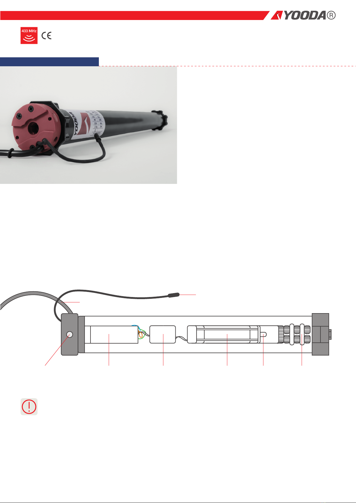
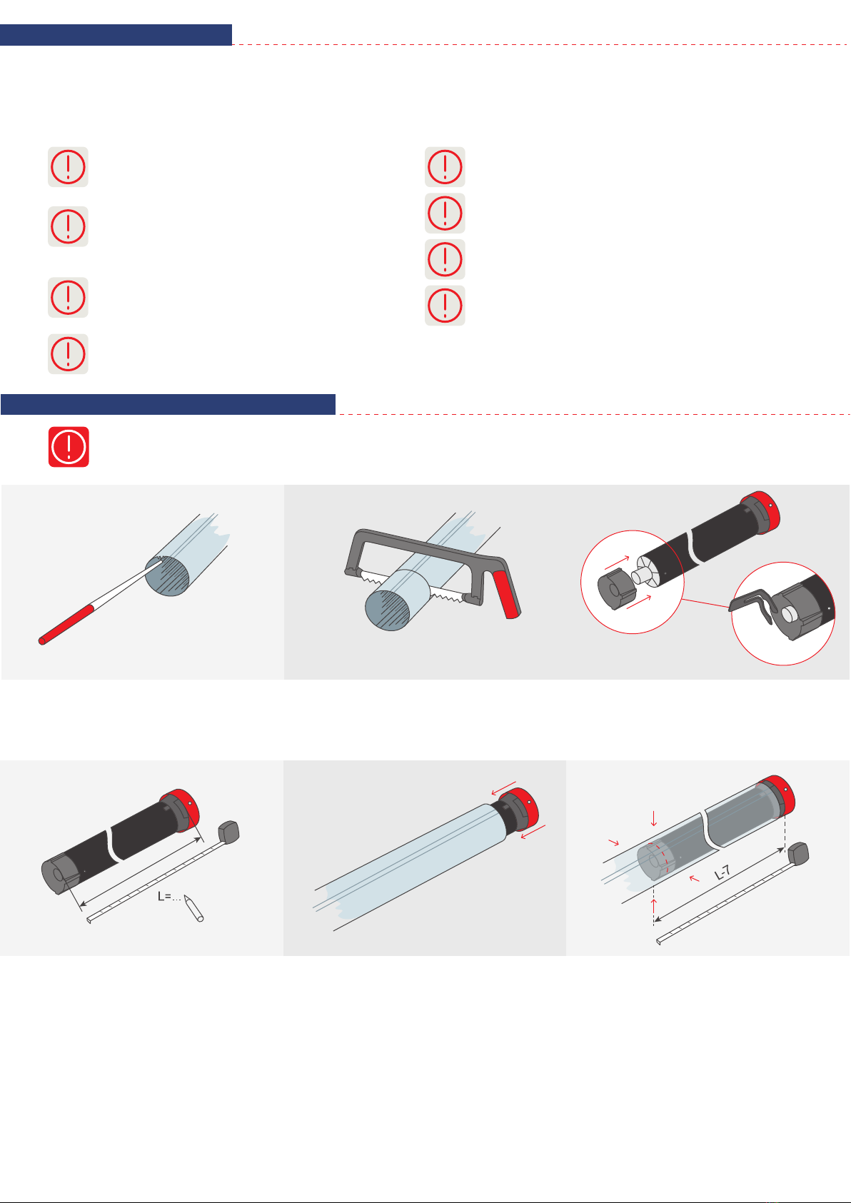
3. Placing motor in the tube
2. Cut the tube to the proper length.1. Deburr the edges
and remove the metal residue.
3. Place the adaptation
on the motor.
4. Measure the distance (L)
between the inner edge of motors head
and the end of the motors adaptor.
5. Insert the motor into the tube
up to the point of connection
between the edge of the tube and
the inner edge of the motors head.
6. Secure the tube to the coupling
part of the adaptation using
4 screws or rivets, placed at L-7 mm
distance from the inner edge of the
motors head.

3
4. Connection
Installation of the tubular motor should be performed by specialists with 1kV or higher SEP-certified electrician's licence
(SEP - Association of Polish Electrical Engineers) or equal license. Device is designed to operate in places shielded from
unfavourable weather conditions. Motor should be installed in accordance with all provisions of regional law and profes-
sional standards. All cables connecting power receiver with electric source should be protected from overload and
short-circuits effects with devices automatically disconnecting power. Device should be powered with a separate source
and protected only with a fast-blow fuse (never slow-blow fuse). Creating electrical system using inadequate fuse may
result in loosing rights under the provisions of warranty. When connecting device to power source with cables with
adequate cross-section should be used. Long-lasting output load capacity table should be the ground for choosing
adequate cable.
230 V AC
phase wire neutral wire protective wire
LN
brown wire - phase
Mounting power supply wire,
antenna and mikroswitch.
230 V / 50 Hz
yellow-green wire - protective
blue wire - neutral
5. Range
Radio receiver range is a variable value and can differ from declared values depending on conditions in which device
operates. Possible sources of changes in range are building construction, interference caused by other radio transmitters
etc.
230 V / 50 Hz 200 m 35 m 433,92 MHz
L1
outdoor L2
indoor Operating
frequency
20
Roller shutter with remotely controlled motor
L2L1

4
6. Programming first transmitter
1. Longer than 4 seconds pause between series of button clicks during programming will cause device to switch off from
programming mode without saving any changes.
2. Programming the first transmitter removes the previously programmed transmitters from memory.
1. Longer than 4 seconds pause between series of button clicks will cause device to switch off from programming mode
without saving any changes.
2. To set the upper and lower limit position press the programming button P2 during the motor movement, it causes the
work displacement. Then you can precisely set the limit positions. Pressing the P2 button again motor will run continu-
ously.
Turn on power supply
or press programming
button on motors head
when power is on.
The roller
shutter will
make a longer
up/down
movement.
Press
programming
button P2.
Press
programming
button P2.
Press
UP button.
The roller shutter will make
a longer up/down
movement - transmitter
has been programmed.
The roller shutter will make
a longer up/down
movement.
The roller shutter will make
a longer up/down
movement.
Turn on power supply
or press programming
button on motors head
when power is on.
The roller
shutter will
make a longer
up/down
movement.
Press
programming
button P2.
Press
programming
button P2.
Press
DOWN button.
The roller shutter will make
a longer up/down
movement - motor has
changed its work direction.
The motor will make a
short up / down movement.
The roller shutter will make
a longer up/down
movement.
The roller shutter
will make a longer
up/down
movement.
Press
programming
button P2.
The roller shutter
will make a short
up/down
movement.
The roller shutter
will make a short
up/down
Press
UP button.
Press
programming
button P2.
Press
UP button.
7. Changing motors direction
8. Programming limit positions
METHOD 1:
Changing the work motor direction removes the previously programmed transmitters from the memory.
METHOD 2:
Changing the work motor direction does not change the limit positions.
Press and hold
programming button
for 5 seconds on
the motor head.
The motor will make short
up/down movement -
motor has changed its
work direction.
When the roller shutter
reaches upper limit position
press STOP button.

1. After setting the upper and lower limit positions, it is possible to set the third position (favorite) between those positions.
2. Hold the STOP button for 3 seconds to set the blind in third limit position.
9. Programming the third limit position
5
When the roller shutter
reaches lower limit position
press STOP button.
Limit positions
has been
programmed.
Press STOP button
5 times at 1 sec
intervals to confirm
the upper limit position.
Press STOP button
5 times at 1 sec
intervals to confirm
the lower limit position.
Press
DOWN button.
The roller shutter will
make a longer
up/down movement.
The roller shutter will
make a longer
up/down movement.
Press
STOP button.
The roller shutter will
make a short
up/down movement.
Upper limit position
has been set.
The third
limit position.
Lower limit position
has been set.
Limit positons have been
removed.
The third limit positon
has been set.
Press
STOP button.
The roller shutter will
make a short
up/down movement.
The roller shutter will
make a longer
up/down movement.
Set the blind
in favourite position.
10. Removing third limit position
11. Removing limit positions
The roller shutter will make
a short up/down movement.
The roller shutter will make
a short up/down movement.
The roller shutter will make
a longer up/down movement.
Press
DOWN button.
Press
programming
button P2.
Press
programming
button P2.
1. Receiver can be controlled by up to 20 transmitters.
2. Longer than 4 seconds pause between series of button clicks during programming will cause device to switch off from
programming mode without saving any changes.
12. Programming another transmitter
Press
programming
button P2.
The third limit positon has
been removed.
Press
STOP button.
The roller shutter will
make a short
up/down movement.
Press
STOP button.
The roller shutter will
make a short
up/down movement.
The roller shutter will
make 2 longer up /
down movements.
Press
programming
button P2.

6
1. Longer than 4 seconds pause between series of button clicks during programming will cause device to switch off from
programming mode without saving any changes.
2. Deleting transmitters causes removing limited positions.
13. Deleting all transmitters
Press programming button P2
on the A remote control.
Remote control
has been programmed.
The roller shutter
will make
a short up/down
movement.
The roller shutter
will make
a short up/down
movement.
The roller shutter
will make a longer
up/down movement.
Press
programming button P2
on the A remote control.
Press
programming button P2
on the B remote control.
The roller shutter will make
a short up/down movement.
The roller shutter
will make a short
up/down movement.
The roller shutter
will make a longer
up/down movement.
Press
STOP button.
Press
programming
button P2.
Press programming button P2
on the remote control.
All transmitters
have been removed.
1. Longer than 4 seconds pause between series of button clicks during programming will cause device to switch off from
programming mode without saving any changes.
2. When the impulse mode is on, pressing the direction button, motor will make a short move.
1. When programming key-ring remotes that do not have additional P2 programming button the same function is
substituted with simultaneous push of STOP and UP buttons.
2. Longer than 4 seconds pause between series of button clicks during programming will cause device to switch off from
programming mode without saving any changes.
14. Activating impulse mode
The roller shutter
will make a short
up/down movement.
Press
programming button P2
on the remote control.
If the motor will make two longer
up/down movement,
THE IMPULSE MODE IS ON.
If the motor will make a longer
up/down movement,
THE IMPULSE MODE IS OFF.
Press
UP button.
Press
DOWN button.
The roller shutter
will make a short
up/down movement.
15. Programming key-ring remotes
Turn on power supply
or press programming
button on motors head
when power is on.
The roller
shutter will
make a longer
up/down
movement.
The roller
shutter will
make a short
up/down
movement.
The roller
shutter will
make a short
up/down
movement.
Press simultaneously
STOP and UP
buttons.
Press simultaneously
STOP and UP
buttons.
Pilot brelok
został zaprogramowany.
The roller shutter will make
a longer up/down
movement.
Press
UP button.
Other YOODA Engine manuals

YOODA
YOODA 35 R/S Series User manual

YOODA
YOODA Cortino DT72EN User manual

YOODA
YOODA DVH55B User manual

YOODA
YOODA 35EVY Series User manual

YOODA
YOODA 18LE Series User manual

YOODA
YOODA Smart Home 45 EM/S Series User manual

YOODA
YOODA 35R User manual

YOODA
YOODA 35EV/S Series User manual

YOODA
YOODA CORTINO DT72LE Series User manual

YOODA
YOODA Ortino DT72TE Series User manual
Popular Engine manuals by other brands

Forest
Forest SHUTTLE iOn Installing

Omron
Omron ACCURAX G5 - user manual

Saito
Saito FA-30S(H) instruction manual

Ingersoll-Rand
Ingersoll-Rand 92RM Series Operation and Maintenance Information

Lombardini
Lombardini CHD series Use & maintenance

GAS GAS
GAS GAS ENDUCROSS EC 125 - PART LIST 2005 PART 1 parts list