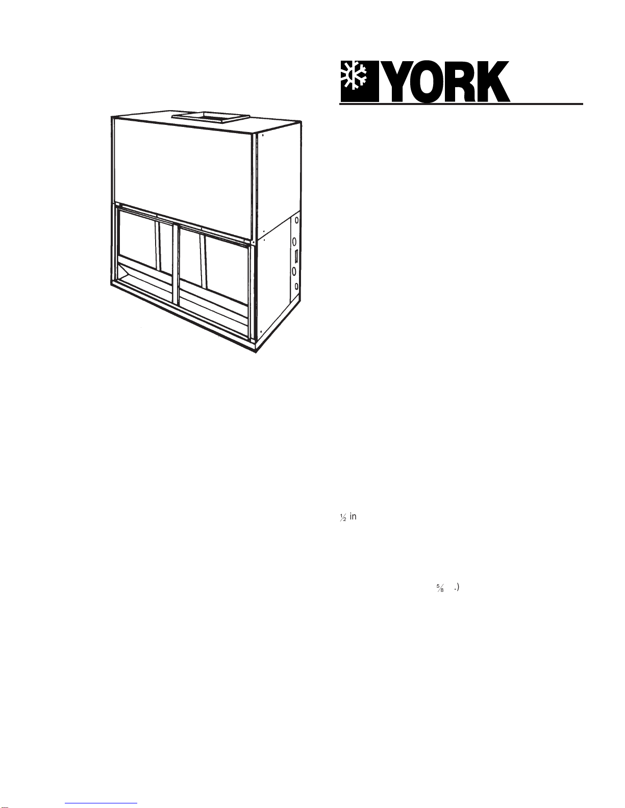
York SUNLINE 2000 KEU180 User manual

DESCRIPTION
This completely assembled unit includes a well-insulated
cabinet, a DX coil with copper tubes and aluminum fins, an
expansion valve, a distributor, throwaway filters, a centrifugal
blower,ablowermotor,anadjustablebeltdrive,ablowermotor
contactorandasmallholdingchargeofrefrigerant-22.Theunit
ismanufacturedunderISO9002QualitySystemCertification.
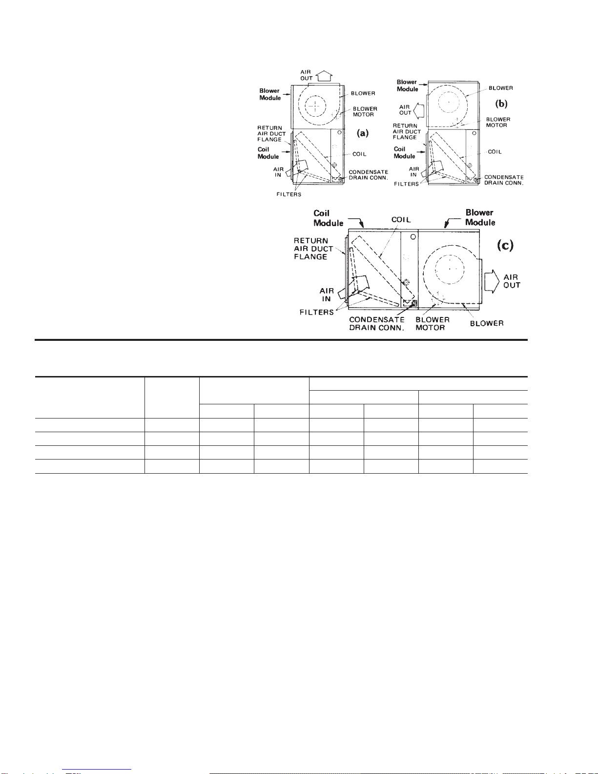
The unit is shipped in the vertical position ready for field
installation. It can be installed for horizontal operation by
reversing the position of the solid bottom panel with the return
air duct flange on the front on the unit.
ACCESSORIES - FIELD INSTALLED
SUPPLY AIR PLENUM - A fully insulated plenum is available
forfreestandingunitslocatedwithintheconditionedspace.Itis
shipped knocked down for easy field assembly, is finished to
match the exterior of the basic unit, and has double deflection
grilles that can be adjusted to vary the throw, spread and drop
of the supply air.
RETURN AIR GRILLE - An expanded metal grille is available
forfreestandingunitslocatedwithintheconditionedspace.Itis
finishedto match theexterior of thebasic unit andis shipped in
one piece for easy installation.
BASE-Abaseisavailabletoraiseverticalunitsabovethefloor.
Outdoor air may be introduced through the base by cutting an
access opening to accommodate the outdoor air duct
connection. The base is finished to match the exterior of the
basic unit. It may have to be insulated in the field for certain
applications.
THREE-PHASE ELECTRIC HEATERS - Electric heaters are
available in four capacities to provide maximum flexibility.Both
the air conditioning unit and the heater can be selected to
precisely match the cooling and heating requirements of the
conditioned space. These heaters are designed for easy field-
installationoverthesupplyairopeningoftheunit.Everyheater
isfullyprotectedagainstexcessivecurrentandtemperatureby
fuses and two high limit thermostats.
Units with electric heat require only one power supply for both
the heating elements and the supply air blower motor. The
power wiring can be protected by either dual element/time
delay fuses or an inverse time circuit breaker.
HOTWATERCOIL-Thisdrainablecoilhastworowsof13mm(
12
in.) copper tubes, eight aluminum fins per 25mm (1 in.), a
casingthatisfinishedtomatchtheexteriorofthebasicunit,but
nowatercontrolvalve.Thecoilslidesoutofthecasingforeasy
fieldinstallation.Itshouldbemountedbetweentheunitcoiland
blower section.
STEAMCOIL-Thenon-freezecoil has one rowof25mm(1in.)
copper tubes, a 16mm (
58
in.) copper tube inside each 25mm
(1 in.) tube to distribute the steam evenly across the entire
length of the coil, eight aluminum fins per 25mm (1 in.), a
casing finished to match the exterior of the basic unit, but no
steam control valve. The coil slides out of the casing for easy
field installation and is pitched in the casing to facilitate
condensate drainage. It should be mounted between the unit
coil and blower sections.
SUSPENSION KIT - Suspension kit 1HH0451 is available for
units installed horizontally. The accessory includes two
channel iron supports and the hardware to secure them to the
topoftheunit.Thehangerrodsmustbesuppliedbythefield.
THERMOSTATS - Wall-mounted thermostats and subbases
(24volt) with system and fan switches are available to control
the operation of these split system air conditioners.
550.39-TG5YI (0601)
SPLIT-SYSTEM
EVAPORATOR BLOWER
K3EU180
15 NOMINAL TONS
SUNLINE 2000
®
(WORLD 50 HZ)

2 Unitary Products Group
550.39-TG5YI
Thisunit hastwo distinctmodules, ablower module
and a coil module. The unit is always shipped in the
vertical position with a vertical air discharge as
shown in illustration (a). The blower module can be
repositionedinthefieldasshowninillustration(b)or
(c) for maximum flexibility.
The Supply Air Plenum, Return Air Grille and Base
accessories can be applied on arrangement (a).
The Return Air Grille and Base accessories can be
applied on arrangement (b).
The Supply Air Plenum, Return Air Grille and
Suspension accessories can be applied on
arrangement (c).
Heater Model UL Test
Voltage Nominal Ratings1Capacity1
Per Stage 1 Per Stage 2
kW Mbh kW Mbh kW Mbh
2HS04501050 415 7.5 25.6 7.5 25.6 - -
2HS04501650 415 12.0 40.9 7.5 25.6 4.5 15.3
2HS04502650 415 19.4 66.5 12.0 40.9 7.5 25.6
2HS04503650 415 26.9 91.9 12.0 40.9 15.0 51.1
1Capacity ratings do not include the heat generated by the supply air blower motor.
2For 380 volts, multiply the mbh and kw values by (380/415)2or 0.838.
HEATING CAPACITY - ELECTRIC HEAT ACCESSORY

Unitary Products Group 3
550.39-TG5YI
STEAM COIL CAPACITY1,kW @ 14 kPa/Mbh @ 2 psig2
Steam Coil Model Blower Model
Used On m3/s / CFM Dry Bulb Temperature of Air Entering Coil, °C/°F
-12 / 10 -1 / 30 10 / 50 21 / 70
1NF0452 KEU180
2.3 / 4800 298.2 / 1018 268.4 / 916 236.7 / 808 211.5 / 722
2.8 / 6000 329.1 / 1124 297.0 / 1014 265.6 / 907 234.1 / 799
3.4 / 7200 356.4 / 1216 321.8 / 1099 287.9 / 983 254.0 / 867
1These capacities do not include any blower motor heat.
2Multiply these capacities by the following factors to correct for higher steam pressures
Steam pressure, kPa/psig 35 / 5 70 / 10 105 / 15 140 / 20 210 / 30
Capacity correction factor 1.06 1.12 1.19 1.25 1.30
NOTE: Steam rate (kg/hr) = 0.66 x kW
(lb/hr) = 1.025xMbh
CAUTION: Do not operate a motor above its nominal HP rating when a unit is equipped
with a steam coil accessory
Water Coil
Model Blower Model
Used On l/s / GPM m3/s / CFM Entering Water Temperature Minus Entering Air Temperature, °C/°F
21 / 70 32 / 90 43 / 110 54 / 130 66 / 150
1HW0451 KEU180 0.95 / 15
2.3 / 4800 135.5 / 463 175.1 / 598 215.8 / 737 257.4 / 879 294.1 / 1004
2.8 / 6000 150.0 / 512 195.0 / 666 240.3 / 820 285.9 / 976 326.6 / 1115
3.4 / 7200 162.4 / 554 210.8 / 720 260.4 / 889 309.8 / 1058 354.3 / 1210
1These capacities do not include any blower motor heat.
NOTE: Water Temperature Drop, °C =
16 71./
xkW
ls
°F =
2
xMbh
GPM
CAUTION: Do NOT operate a motor above its nominal HP rating when a unit is equipped with a hot water coil accessory.
HOT WATER COIL CAPACITY1, kW/Mbh
1HW0450 l/s / GPM 0.63 / 10 / 1.26 / 20 1.90 / 30
Pressure Drop,
kPa / psig/ 0.7 / 0.10 2.2 / 0.32 4.7 / 0.67
1HW0451 l/s / GPM 0.95 / 15 1.90 / 30 2.83 / 45
Pressure Drop,
kPa / psig 1.2 / 0.17 4.0 / 0.58 8.5 / 1.22
Meters (H2O) = 45,942 x kPa
Feet (H2O) = 2031 x psi
PRESSURE DROP VS L/S / GPM
1HW0450 l/s / GPM 1.26 / 20 1.90 / 30
Capacity
Correction 1.12 1.15
1HW0451 GPM 1.90 / 30 2.83 / 45
Capacity
Correction 1.11 1.15
CAPACITY CORRECTION VS
L/S / GPM

4 Unitary Products Group
550.39-TG5YI
SUPPLY AIR BLOWER PERFORMANCE1- (m3/s)
BLOWER
SPEED
RPM
AIRFLOW
ESP2
(Pa) OUTPUT
(kW) INPUT
(kW) ESP2
(Pa) OUTPUT
(kW) INPUT
(kW) ESP2
(Pa) OUTPUT
(kW) INPUT
(kW) ESP2
(Pa) OUTPUT
(kW) INPUT
(kW) ESP2
(Pa) OUTPUT
(kW) INPUT
(kW)
2.26 m3/s 2.55 m3/s 2.83 m3/s 3.11 m3/s 3.40 m3/s
600 114 1.07 1.34 74 1.25 1.56 27 1.46 1.80 - - - - - -
615 136 1.15 1.43 99 1.33 1.64 55 1.55 1.90 3 1.08 2.20 - - -
700 208 1.36 1.68 174 1.58 1.94 134 1.81 2.22 89 2.06 2.54 30 2.32 2.82
800 312 1.77 2.17 285 2.01 2.47 248 2.26 2.74 206 2.51 3.05 154 2.79 -
900 422 2.20 2.68 404 2.46 2.99 311 2.73 - - - - - - -
SUPPLYAIR BLOWER PERFORMANCE1
- (CFM)
BLOW
SPEED
ER
RPM
AIRFLOW
ESP2
(IWG) OUTPUT
(BHP) INPUT
(kW) ESP2
(IWG) OUTPUT
(BHP) INPUT
(KW) ESP2
(IWG) OUTPUT
(BHP)INPUT
(kW) ESP2
(IWG) OUTPUT
(BHP)INPUT
(kW) ESP2
(IWG) OUTPUT
(BHP) INPUT
(kW
4800 CFM 5400 CFM 6000 CFM 6600 CFM 7200 CFM
600 0.46 1.44 1.34 0.30 1.68 1.56 0.11 1.96 1.80 - - - - - -
615 0.55 1.54 1.43 0.40 1.79 1.64 0.22 2.08 1.90 0.01 2.41 2.20 - - -
700 0.84 1.83 1.68 0.70 2.12 1.94 0.54 2.43 2.22 0.36 2.77 2.54 0.12 3.12 2.82
800 1.26 2.38 2.17 1.15 2.70 2.47 1.00 3.03 2.74 0.83 3.37 3.05 0.62 3.75 -
900 1.70 2.95 2.68 1.63 3.30 2.99 1.52 3.67 - - - - - - -
1Unit resistance is based on a wet evaporator coil and clean filters.
2Available static pressure in Pa (IWG) to overcome the resistance of the duct system and any accessories added to the unit.
NOTE:Motorscanbeselectedtooperateintotheservicefactorbecausetheyarelocatedinthemovingairstream,upstreamofany
heating device.
LEGEND:
SUPPLY AIR BLOWER PERFORMANCE
Exceeds the output limitation of the standard
factory-mounted blower motor.
RPM range for standard factory-
mounted drive components.

Unitary Products Group 5
550.39-TG5YI
Static resistances, IWG
Unit Model Accessory CFM
4800 5400 6000 6600 7200
KEU180
Electric Heat
10 kW 0.04 0.05 0.06 0.08 0.10
16kW 0.07 0.09 0.11 0.14 0.17
26 kW 0.13 0.16 0.20 0.24 0.29
36 kW 0.20 0.24 0.29 0.35 0.42
Supply Air Plenum 0.03 0.04 0.05 0.06 0.07
Return Air Grille 0.04 0.05 0.06 0.07 0.08
Hot Water Coil 0.18 0.22 0.26 0.03 0.34
Steam Coil 0.15 0.18 0.22 0.26 0.30
Static resistance, pascal
Unit Model Accessory m3/s
2.26 2.55 2.83 3.11 3.40
KEU180
Electric Heat
10 kW 10 12 15 20 25
16 kW 18 21 27 35 42
26 kW 32 40 50 60 72
36 kW 50 60 72 87 106
Supply Air Plenum 8 10 12 15 18
Return Air Grille 10 12 15 18 20
Hot Water Coil 45 55 64 74 84
Steam Coil 37 45 55 64 74
STATIC RESISTANCES FOR UNIT ACCESSORIES

6 Unitary Products Group
550.39-TG5YI
Model
KEU CFM Face
Velocity
(FPM)
Sound
Power
dB (10)
12 Watts
Angle of Deflection
Vertical Louvers1
0° Spread Horizontal
Louvers2Vertical Louvers1
22
12
° Spread Horizontal
Louvers2Vertical Louvers1
45° Spread Horizontal
Louvers2
Throw
(Feet)3Spread
(Feet)30° 18° Throw
(Feet)3Spread
(Feet)3 0° 18° Throw
(Feet)3Spread
(Feet)3 0° 18°
Min Max Min Max Drop
(Feet)4Min Max Min Max Drop
(Feet)4
180
4800 880 26 84 132 32 48 23 12 61 95 38 56 21 11 46 72 73 112 12 6
5400 1000 28 95 149 36 54 24 12 68 107 42 63 22 11 52 81 81 124 12 6
6000 1110 30 106 165 39 59 25 13 76 119 46 69 23 12 57 89 90 138 13 7
6600 1220 33 116 182 43 65 26 13 84 131 50 76 23 12 63 98 99 152 13 7
7200 1330 36 126 199 46 70 27 14 92 143 55 83 24 12 68 107 109 166 14 7
1Adusting the vertical louvers will vary the throw, the spread and the drop.
2Adjusting the horizontal louvers will only vary the drop.
3The velocity of the air will be 125 ft/min. at the minimum distance and 80 ft/min. at the maximum distance.
4The velocity of the conditioned air at the bottom of the drop will be 50 ft./min. Drafts will occur if the drop extends into the
occupied level of the conditioned space.
SUPPLY AIR PLENUM PERFORMANCE DATA, CFM
Model
KEU m3/s Face
Velocity
(MPM)
Sound
Power
dB (10)
12 Watts
Angle of Deflection
Vertical Louvers1
0° Spread Horizontal
Louvers2Vertical Louvers1
22
12
° Spread Horizontal
Louvers2Vertical Louvers1
45° Spread Horizontal
Louvers2
Throw
(Meters)3Spread
(Meters)30° 18° Throw
(Meters)3Spread
(Meters)3 0° 18° Throw
(Meters)3 Spread
(Meters)30° 18°
Min Max Min Max Drop
(Meters)4Min Max Min Max Drop
(Meters)4
180
2.26 268 26 25.5 40.1 9.7 14.6 7.0 3.6 18.5 28.9 11.6 17.0 6.4 3.3 14.0 22.0 22.2 34.0 3.6 1.8
2.55 304 28 28.9 45.3 10.9 16.4 7.3 3.6 20.7 32.5 12.8 19.2 6.7 3.3 15.8 24.6 24.6 37.7 3.6 1.8
2.83 337 30 32.2 50.1 11.9 18.0 7.6 4.0 23.1 36.2 14.0 21.0 7.0 3.6 17.3 27.0 27.4 42.0 4.0 2.1
3.11 371 33 35.3 55.3 13.1 20.0 7.9 4.0 25.5 40.0 15.2 23.1 7.0 3.6 19.2 29.8 30.1 46.2 4.0 2.1
3.40 404 36 38.3 60.5 14.0 21.3 8.2 4.3 28.0 43.5 16.7 25.2 7.3 3.6 20.7 32.5 33.1 50.5 4.3 2.1
1Adusting the vertical louvers will vary the throw, the spread and the drop.
2Adjusting the horizontal louvers will only vary the drop.
3The velocity of the air will be 125 ft./min. at the minimum distance and 80 ft./min. at the maximum distance.
4The velocity of the conditioned air at the bottom of the drop will be 50 ft./min. Drafts will occur if the drop extends into the
occupied level of the conditioned space.
SUPPLY AIR PLENUM PERFORMANCE DATA,
Motor
(kW/HP) Blower
Range
(RPM)
Adjustable Motor Pulley Fixed Blower Pulley Belt
Pitch Dia
(mm/in.) Bore
(mm/in.) Pitch Dia.
(mm/in.) Bore
(mm/in/) Designation Pitch Lg.
(mm/in.)
2.2 / 3 615/800 86 - 112/
3.4 - 4.4 22.2 /
78
203 / 8.0 25 / 1 A54 1405 / 55.3
BLOWER MOTOR AND DRIVE DATA
M3/S

Unitary Products Group 7
550.39-TG5YI
Description Unit Model
KEU180
Evaporator Coil
Rows Deep & Rows High 3 x 32
Finned Length - mm/inches 1372 / 54
Face Area - square meters/square feet 1.15 / 12.4
Tube OD - mm /inches 9.5 / 3/8
Fins per 25mm (1 in.) 13
Centrifugal Blower
(Forward Curve) Wheel Dia. x Width - mm (inches) 475 x 475
(18 x 18)
Motor1Nominal HP Rating 3
Filters
(Throwaway) Quantity per unit 508mm x 508mm x 25mm
20" x 20" x 1" 6
Face area - square meters/square feet 1.55 / 16.7
Distributor One per unit 7-4-13
Operating Weight
kg/lbs
Basic Unit 390 / 177
Accessories
Supply Plenum 51.7 / 114
Return Air Grille 9.1 / 20
Hot Water Coil 49.9 / 110
Steam Coil 51.3 / 113
Base 45.4 / 100
Electric Heater
10 kW 37.6 / 83
16 kW 29.9 / 66
26 kW 32.2 / 71
36 kW 33.5 / 74
Hot Water Coil
Tube OD, mm/inches
12
/ 12.7 (copper)
Rows Deep 2
Fins per 25mm (1 in.) 8 (aluminum)
Face Area, square meters/square feet 0.63 / 6.8
Connections (supply & return) 25mm (1") NPTE
Steam Coil
Outer Tube OD, mm/inches 25 / 1 (brass)
Rows Deep 1
Fins per 25mm (1 in.) 8 (aluminum)
Face Area, square meters/square feet 0.94 / 10.1
Connection Inlet 38mm (1
12
“) NPTE
Outlet 38mm (1
12
“) NPTE
Electric Heater Heater Elements % Nickel 59.2
% Chromium 16.0
Watt Density, watts/sq. in. 59.0
Face Area, square meters/square feet 0.28 / 3.0
Shipping Volume - cubic meters/cubic feet/ (Basic Unit) 2.5 / 88
1Refer to Blower Motor and Drive Data table for additional motor and drive data.
2Refer to the unit Installation Instruction 550.39-N5YI for the distributed weight of the evaporator blower unit.
PHYSICAL DATA - UNITS AND ACCESSORIES

8 Unitary Products Group
550.39-TG5YI
UNIT DIMENSIONS
ACCESSORIES
•ELECTRIC HEATER
Add 381mm (15 in.) to Unit Height when using 10, 16, 26 or 36kW Heater
•SUPPLY AIR PLENUM
Add 686mm (27 in.) to Unit Height when used
•BASE
Add 610mm (24 in.) to Unit Height when used
MINIMUM CLEARANCES (mm/in.)
Side with RETURN AIR opening - 610 / 24
Side with SUPPLY AIR opening - 610 / 241
Side with PIPING CONNECTIONS - 1549 / 612
Side opposite PIPING CONNECTIONS - 660 / 263
Bottom - 4
1 Overall dimension of the unit will vary if an electric heater, a supply air plenum or a base is used.
2This dimension is required for removal of the DX coil. Only 660mm (26 in.) is required for normal
servicing.
3If the DX coil has to be removed, this dimension is required to loosen screws that secure the coil to
the unit frame. This dimension will also be required for blower motor access if the piping
connections are made on the opposite side of the unit.
4Allow enough clearance to trap the condensate drain line.
All dimensions are in millimeters and inches. They are sub-
ject to change without notice. Certified dimensions will be
provided upon request.

Unitary Products Group 9
550.39-TG5YI
ACCESSORY DIMENSIONS
REFER TO THE UNIT DRAWING FOR
DUCT FLANGE DIMENSIONS.
STEAM COIL 38mm
(1
12
) NPTE
CONN'S.
51mm
(2")
Coil
Model Unit
Model Steam coil Dimensions, mm (inches)
ABCDEF
1NF0452* KEU180 1543
(60
34
)819
(32
14
)152
(6) 76
(3) 89
(3
12
)445
(17
12
)
* Installs between the unit coil section and the blower section.
25mm
(1") NPTE
CONN'S.
502"
Coil Model Unit
Model Water Coil Dimensions, mm (inches)
ABCDEF G
1HW0452* KEU180 154
(60
34
)819
(32
14
)152
(6) 58
(2
532
)84
(3
516
)98
(3
2732
)170
(6
11
16
)
KNOCKOUT FOR POWER
AND
CONTROL WIRING
(2 (3
WITH ELECTRIC HEAT - Remove the 66mm (2
12
in.) knockout and one of the 22.2mm
(
78
in.) knockouts from the rear panel of the plenum. Remove the 43.7mm (1
2332
in.) knock-
out and one of the
78
“ (22.2mm) knockouts from the top panel of the basic unit. Install a
12.7mm (
12
in.) squeeze connector in both of the 22.2mm (
78
in.) openings.
Route the power wiring conduit through the 64mm (2
12
in.) opening and connect it to the
field-supplied fitting on the electric heat accessory. Connect the power wiring to the fuse
block in the heater control box.
Route the control wires through the 22.2mm (
78
in.) openings and connect them to the ter-
minals on block 4TB. Secure them with the 12.7mm (
12
in.) squeeze connectors.
WITHOUT ELECTRIC HEAT - Remove both 22.2mm (
78
in.) knockouts from the rear panel
of the plenum and both 22.2mm (
78
in.) knockouts from the top panel of the basic unit. In-
stall a 12.7mm (
12
in.) squeeze connector in one of the plenum openings and both of the
unit openings. Install a 12.7mm (
12
in.) conduit fitting in the other opening of the plenum.
Connect the power wiring conduit to the fitting on the plenum. Route the power wiring
through the conduit, one of the squeeze connectors on the unit, and the field-supplied
squeeze connector on the blower motor contactor.
Route the control wires through the remaining plenum and unit openings aand connect
them to the terminals on block 4TB. Secure them with the 12.7mm (
12
in.) squeeze connec-
tors.
(
Accessory
Model Unit Model Plenum Dimensions, mm (inches)
ABCDEFGHKL
1SP0452 KEU180 1543
(60
34
)787
(31) 686
(27) 1695
(66
34
)505
(19
78
)156
(6
18
)25
(1) 64
(2
12
)495
(19
12
)44
(1
34
)

10 Unitary Products Group
550.39-TG5YI
ACCESSORY DIMENSIONS
This opening in the bottom of the
heater control box is used for the
wiring harness that connects the
heateraccessorytothebasicunit.It
is provided with a squeeze
connector for securing the the
wiring harness. Its location
corresponds to the location of the
43.7mm (1
2332
in.) knockout in the
top panel of the basic unit.
ELECTRIC HEATER
WIRING HARNESS
LOCATION
ACCESS OPENING FOR
POWER SUPPLY WIRING
19
(
34
)
13
(
12
)
10kW THRU 36kW - Add 32mm (1
14
in.) conduit fitting to the
43.7mm (1
2332
in.) hole for wire sizes up through #1 AWG Remove
the knockout ring and add a 38mm (1
12
in.) conduit fitting to the
50mm (1
3132
in.) hole for wire sizes up through #0 AWG.
Accessory
Model Nom
. kW Heater Dimensions, mm (inches)
ABCDEFGHKLM
2HS04501050
2HS04501650
2HS04502650
2HS04503650
10
16
26
36
692
(27
14
)641
(25
14
)362
(14
14
)25
(1) 102
(4) 13
(
12
)140
(5
12
)38
(1
12
)25
(1) 565
(22
14
)489
(19
14
)
Blower Motor
kW/HP Power Supply FLA LRA Maximum
Fuse Size* Amps Maximum
Wire Length* * m (Ft.)
2.2 / 3 380/415-3-50 5.2 37.0 10 122 (400)
* Dual element, time delay fuses.
ELECTRICAL DATA
COOLING ONLY UNITS
Heater Nominal Heat Volt Heat FLA Motor FLA Ampacity Maximum
Fuze Size,
Amps*
Wire Size
(Copper Con-
ductor)
Maximum
Wire Length,
m (Ft.)**
10 kW 7.5 415 10.4 5.2 19.5 20 12 AWG 45.6 (150)
16 kW 12.0 415 16.6 5.2 27.3 30 10 AWG 53.2 (175)
26 kW 19.4 415 27.0 5.2 40.3 45 8 AWG 53.2 (175)
36 kW 26.9 415 37.4 5.2 53.3 60 6 AWG 68.4 (225)
* Dual element, time delay fuses.
** Based on three 60° C, 14 AWG, insulated copper conductors in steel conduit and a 3% voltage drop.
UNITS WITH ELECTRIC HEAT

Unitary Products Group 11
550.39-TG5YI
TERMINALSONBLOCK3TBOF
THE BLOWER UNIT
TERMINALS ON
1-STAGE COOLING
THERMOSTAT
2TH13700424
FIELD WIRING
Cooling only
CONTROL WIRING
Units with steam or hot water coil AC-
Units with electric heat accessory

Subject to change without notice. Printed in U.S.A
Copyright by York International Corporation 2001. All Rights Reserved.
5005
York
Drive
550.39-TG5Y (0601)
Supersedes: 550.39-TG5Y(0501)
Norman
OK
73069
Unitary
Products
Group
Table of contents
Other York Blower manuals

York
York EVAPORATOR BLOWERS K2EU060 Quick start guide

York
York MAL-MAM 18 Quick start guide

York
York SUNLINE K4EU120A50A User manual

York
York YUHC 18 User manual

York
York EUKC-18 AA User manual

York
York LEU360 Quick start guide

York
York HORIZONTAL AIR RETURN CER00 User manual

York
York WORLD 50 HZ K3EU180A50 User manual

York
York NE090 Quick start guide

York
York 480 Quick start guide
Popular Blower manuals by other brands

GreenWorks
GreenWorks BA24B210 Operator's manual

Clarke
Clarke RSW 37 Operator's manual

GreenWorks Pro
GreenWorks Pro BL60L00 Operator's manual

Oleo-Mac
Oleo-Mac Multi-Mate owner's manual

Grizzly
Grizzly BLSB 3030 Translation of the original instructions for use

Eagle power
Eagle power TKS510ET Operation & maintenance manual