York YUHC 18 User manual

Blower
YUHC 18 to 60
SERVICE MANUAL
YUHC 18 · YUHC 24 · YUHC 36
YUHC 36 · YUHC 48 · YUHC 60
SM-YUHC-18-60GB 03-07

How to read the model?
Y U H C 24 F U B A A A
Range:
F = Floor standing
H = High wall
M = Master range
P = Portable
Y = YORK
R = Everest front
Refrigerant type:
A = R22
B = R407C
C = R410A
Capacity Btu/h
Generation:
A = First
R = New remote
Voltages:
A =
(Out) 220-240/1/50 - (In) 220-240/1/50
C =
(Out) 380/3/50 - (In) 220-240/1/50
Indoor options:
A = Standard
J = Bio Screen filter
** Omit for outdoor units
Outdoor options:
A = Standard
B = Low Ambient Kit
C = Power outdoor
* Omit for indoor units
Indoors:
A = Free matching multi
S = Single
T = Duct High Static
U = Duct standard case
Compressor type:
A = AC Inverter
D = DC Inverter
F = Fixed
M = Multi
* * *
Family:
A = Efficiency Ultra
E = Eco Ultra
H = Alps
J = Atlas
K = Cassette
L = Ultra
M = Multi Ultra
R = Multi Inverter
V = Inverter Ultra
U = Ducted unit
O = Floor / Ceiling
Type:
C = Set - Cooling only
D = Outdoor - Cooling only
E = Indoor - Cooling only
H = Set - Heat pump
J = Outdoor Heat pump
K = Indoor Heat pump
M = Multi Ultra
R = Multi Inverter
V = Inverter Ultra
U = Ducted unit
O = Floor / Ceiling

Duct Type
Part1. Product features
1. Economic and convenient installation
---Several diffusers branch off from an indoor unit, adjusting the room temperature, which makes many rooms to
be air conditioned with only one indoor unit
---All models feature thin design making them applicable to ceiling pocket that tends to be shallow
2) Awild variety of optional accessories
---Including front clapboard, panel, canvas air passage, filter, etc.
Canvas air passage Clapboard
Panel
3) Along-life and high-efficiency filter
Filter
4) Way of air intake and inserting air filter
---Air intake can be positioned either at the back or below the unit. Similarly, the air filter also can be inserted
either from the back or from the bottom of the unit.

Part2. Specification
Model YUHC-18 YUHC-24 YUHC-30
Power supply Ph-V-Hz 1,220-240V,50Hz 1,220-240V,50Hz 3,380V,50Hz
Capacity Btu/h 18,000 24,000 30000
Capacity kW 5.3 7.1 8.8
Input W 1900 2560 3250
Rated current A 8.8 12.2 5.5
Cooling
EER Btu/w.h 9.5 9.4 9.3
Capacity Btu/h 20,500 27,300 32000
Capacity kW 6.1 8.0 9.4
Input W 1900 2500 3250
Rated current A 8.8 11 5.5
Heating
COP Btu/w.h 11 11 10
Moisture Removal l/h 1.9 2.4 3
Max. input consumption W 2300 3300 4620
Max. input current A 11.7 15.3 8.5
Starting current A 45 60 31
Model PA225X2CS-4KU PA290X3CS-4MU1 C-SBN303H8D
Type ROTARY ROTARY SCROLL
Brand TOSHIBA TOSHIBA SANYO
Supplier TOSHIBA TOSHIBA SANYO(Dalian)
Capacity Btu/h 18362 24574 33500
Input W 1855 2440 3650
Rated current (RLA) A 8.6 11.4 6.58
Locked rotor Amp (LRA) A 80 85 65
Thermal protector INNER INNER INNER
Capacitor uF 50 50 /
Compressor
Refrigerant oil ml 750 950 1700
Model YSK55-4D YSK74-4C YSK59-4A
Brand WELLING WELLING WELLING
Input W 117 170 118
Capacitor uF 3 4 2.5uF/450V
Indoor fan
motor
Speed (hi/mid/lo) r/min 900/800/690 1100/1020/900 820/695/620
Number of rows 2 3 3
Tube pitch(a)x row pitch(b) mm 25.4×22 25.4×22 25.4×22
Fin spacing mm 1.7 1.7 1.7
Fin type (code) Hydrophilic Hydrophilic Hydrophilic
Tube outside dia. and type mm Ø9.53, bare tube Ø9.53, bare tube Ø9.53 innergroove
Coil length x height x width mm 800×254×44 800×254×66 1150×254×44
Indoor coil
Number of circuits 3 3 4
Indoor air flow m3/h 1060 1260 1400
Indoor external static pressure (Hi) Pa 40 40 70
Indoor noise level (Hi/Lo) dB(A) 38/35 38/35 44/40

Dimension (W*H*D) mm 1000×300×800 1000×300×800 1350×300×800
Packing (W*H*D) mm 1205×370×940 1205×370×940 1555×370×940
Indoor unit
Net/Gross weight kg 36/43 38/45 48/57
Model YDK53-6K YDK53-6H YDK250-6D-WL
Brand WELING WELLING WELLING
Input W 130 130 307
Capacitor uF 2.5 3 10
Outdoor fan
motor
Speed r/min 750 800 740
Number of rows 2 2 2
Tube pitch(a)x row pitch(b) mm 25.4×22 25.4×22 25.4×22
Fin spacing mm 1.8 1.5 1.7
Fin type (code) Hydrophilic aluminium Hydrophilic aluminium Unhydrophilic aluminium
Tube outside dia.and type mm Ф9.53, innergroove tube Ф9.53, innergroove tube Ф9.53, innergroove tube
Coil length x height x width mm 775×660×44 850×810×44 955×915×44
Outdoor coil
Number of circuits 3 4 8
Outdoor air flow m3/h 2400 3000 5000
Outdoor noise level dB(A) 48 55 57
Dimension (W*H*D) mm 845×695×335 895×860×330 990×960×360
Packing (W*H*D) mm 965×847×395 1000×985×410 1120×1090×435
Outdoor unit
Net/ Gross weight kg 55/58 79/90 101/106
Refrigerant type/Quantity g R410A/2050 R410A/2600 R410A/3100
Design pressure (high side/low side) MPa 4.2/2.5 4.2/2.5 4.2/2.5
Liquid side mm(inch) 6.35 (1/4) 9.53 (3/8) 12.7 (1/2)
Gas side mm(inch) 12.7 (1/2) 16 (5/8) 19 (3/4)
Max. pipe length m 30 30 30
Refrigerant
piping
Max. difference in level m 20 20 20
Operation temp ºC 17~30 17~30 17~30
Ambient temp ºC -7~45 -7~45 -7~45
Application area m234~49 40~56 50~75
Qty’per 20’ /40’ /40'HQ set 34/76/94 34/76/94 24/52/62

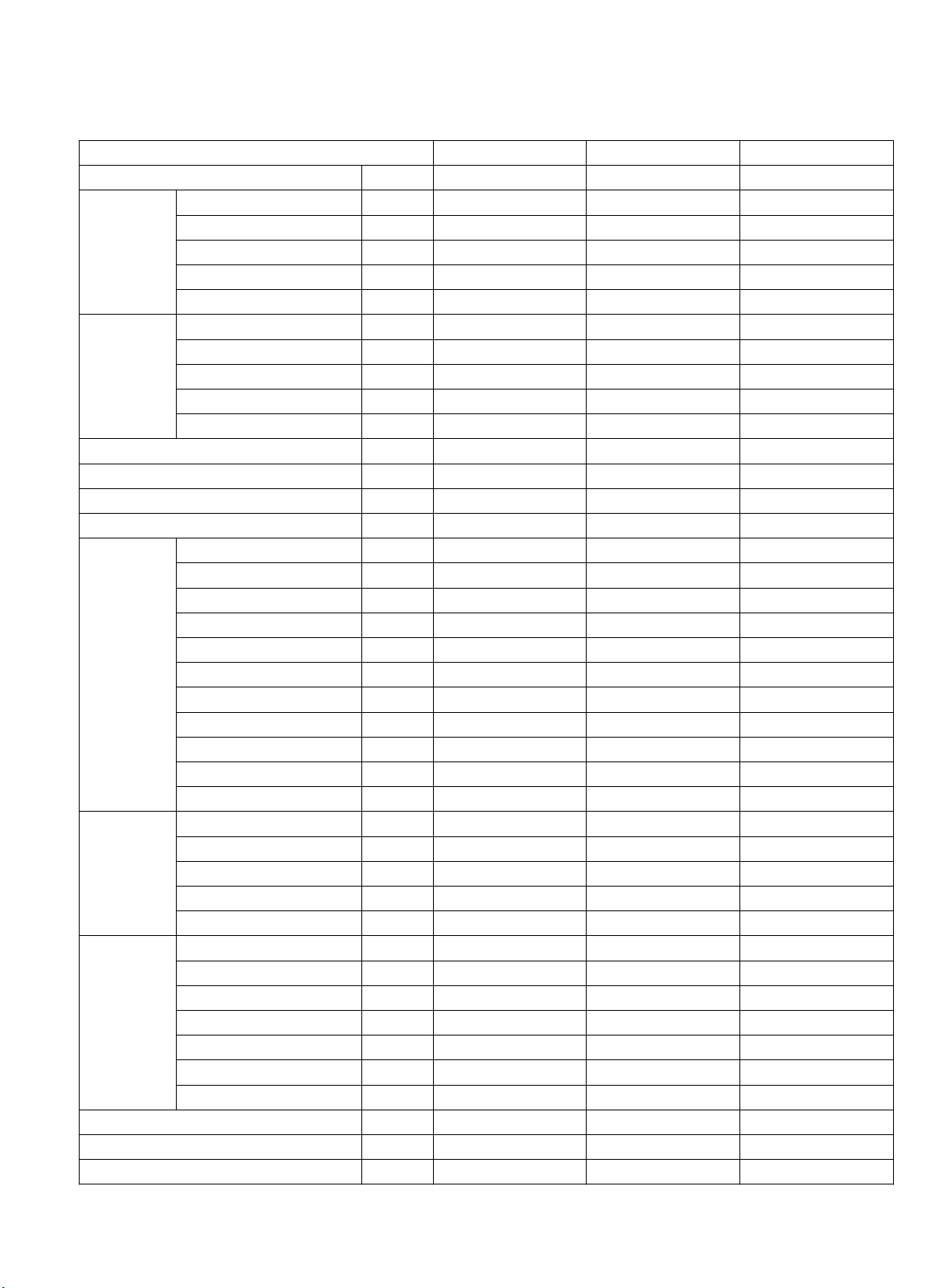
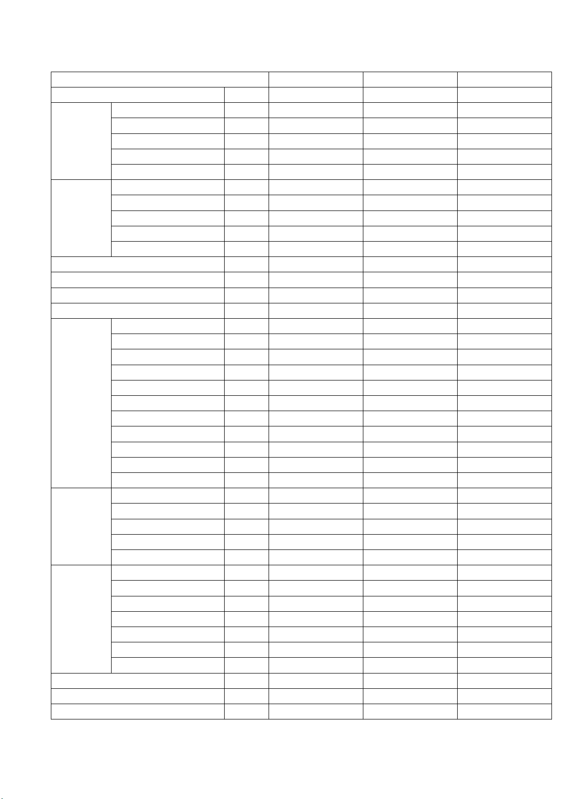
Model YUHC-36 YUHC-48 YUHC-60
Power supply Ph-V-Hz 3,380V,50Hz 3,380V,50Hz 3,380V,50Hz
Capacity Btu/h 36,000 48,000 60,000
Capacity kW 10.5 14.0 16.0
Input W 3700 4700 6000
Rated current A 6.5 8.2 9.8
Cooling
EER Btu/w.h 9.7 10.2 10
Capacity Btu/h 39,000 52,000 68,000
Capacity kW 12 15.2 20,000
Input W 3350 4900 6000
Rated current A 5.8 8.6 9.8
Heating
COP Btu/w.h 11.6 10.6 11.3
Moisture Removal l/h 3.6 4.6 6
Max. input consumption W 4620 5870 7500
Max. input current A 8.5 10.7 12.8
Starting current A 31 41 44
Model C-SBN303H8D C-SBN373H8D C-SBN453H8D
Type SCROLL SCROLL SCROLL
Brand SANYO SANYO SANYO
Supplier SANYO(Dalian) SANYO(Dalian) SANYO(Dalian)
Capacity Btu/h 33500 48123 559732
Input W 3650 4750 5750
Rated current (RLA) A 6.58 8.22 9.77
Locked rotor Amp (LRA) A 65 82 66
Thermal protector INNER INNER INNER
Capacitor uF / / /
Compressor
Refrigerant oil ml 1700 1700 1700
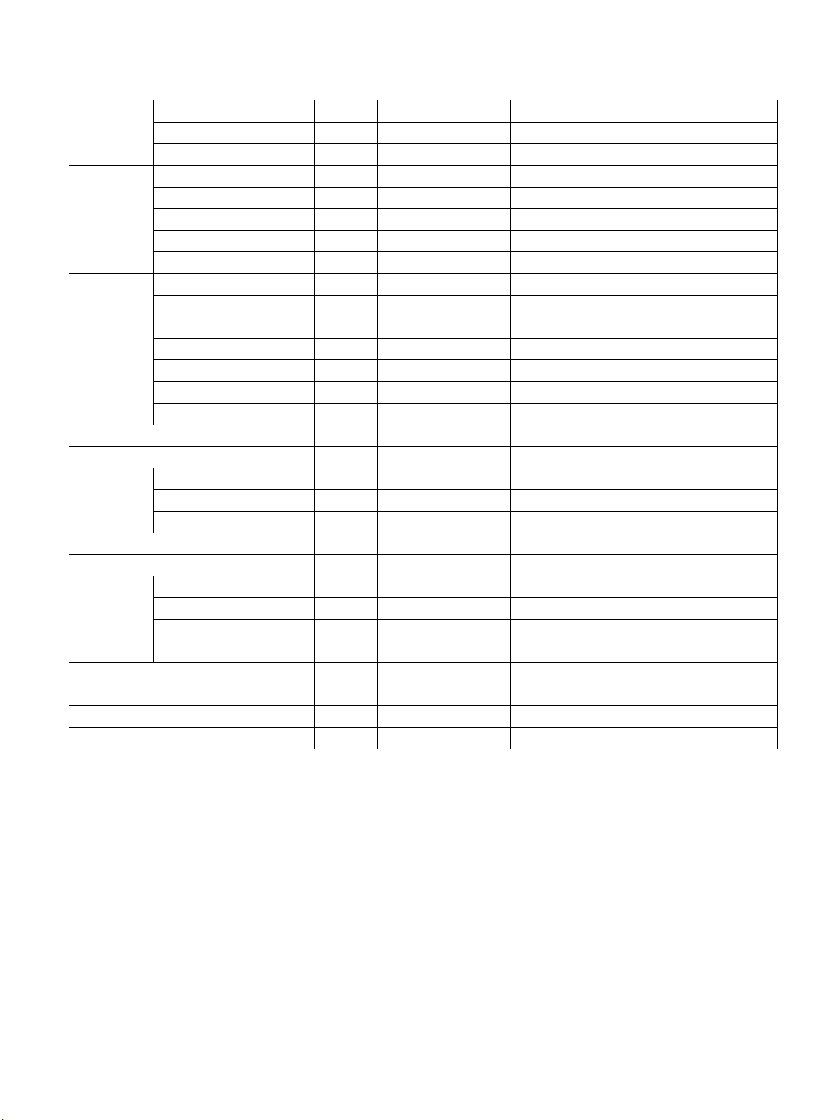
Model YSK59-4A YSK59-4A YSK160-6
Brand WELLING WELLING WELLING
Input W 118 118 227
Capacitor uF 2.5uF/450V 2.5uF/450V 6
Indoor fan
motor
Speed (hi/mid/lo) r/min 820/695/620 820/695/620 870/770/650/580
Number of rows 3 3 3
Tube pitch(a)x row pitch(b) mm 25.4×22 25.4×22 25.4×22
Fin spacing mm 1.7 1.7 1.7
Fin type (code) Hydrophilic aluminium Hydrophilic aluminium Hydrophilic aluminium
Tube outside dia. and type mm Ø9.53 innergroove tube Ø9.53 innergroove tube Ø9.53 innergroove tube
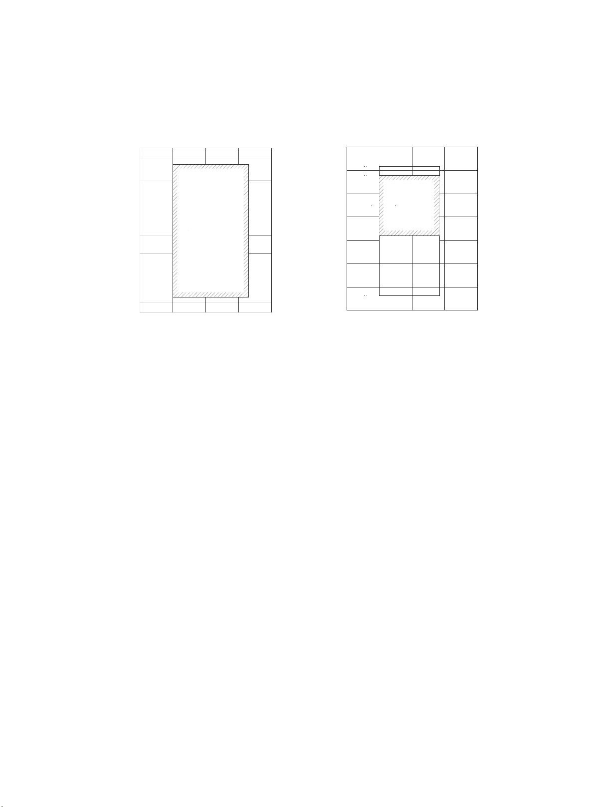
Coil length x height x width mm 1150×254×44 1150×254×44 1150×305×66
Indoor coil
Number of circuits 4 4 4
Indoor air flow m3/h 1550 1600 1900
Indoor external static pressure (Hi) Pa 70 70 96
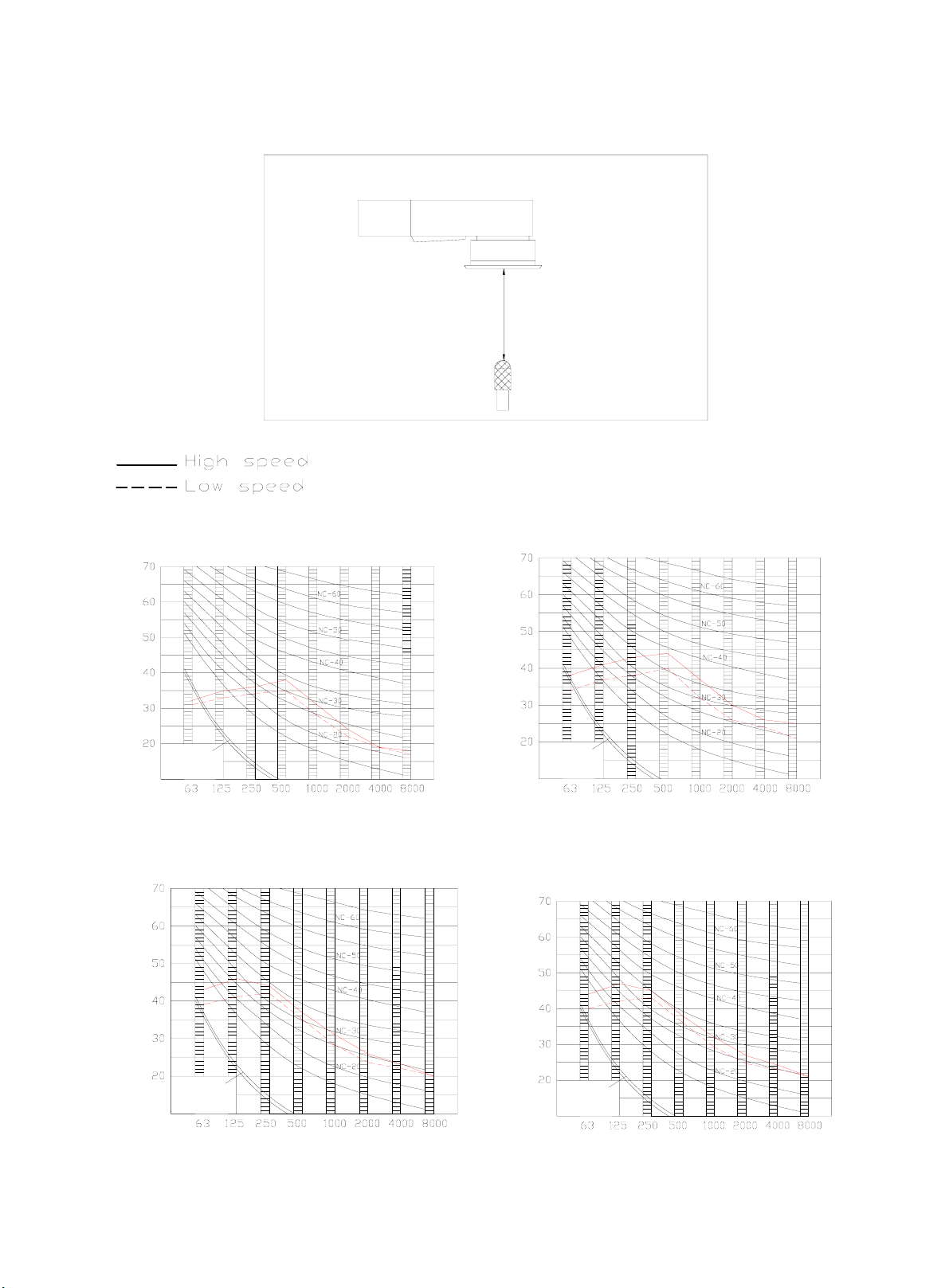
Indoor noise level (Hi/Lo) dB(A) 44/40 46/42 47/43

Dimension (W*H*D) mm 1350×300×800 1350×300×800 1350×320×800
Packing (W*H*D) mm 1555×370×940 1555×370×940 1555×440×940
Indoor unit
Net/Gross weight kg 48/57 50/59 70/80
Model YDK250-6D-WL YDK65-6WL; YDK65-6F YDK65-6WL; YDK65-6F
Brand WEILING WELLING WELLING
Input W 307 138+156 138+156
Capacitor uF 10 3.5×2 3.5×2
Outdoor fan
motor
Speed r/min 740 800 800
Number of rows 2 2 2
Tube pitch(a)x row pitch(b) mm 25.4×22 25.4×22 25.4×22
Fin spacing mm 1.7 1.8 1.8
Fin type (code) unhydrophilic hydrophilic hydrophilic
Tube outside dia.and type mm Ф9.53, Ф9.53, Ф9.53,
Coil length x height x width mm 955×915×44 715×1220×44 715×1220×44
Outdoor coil
Number of circuits 8 4 4
Outdoor air flow m3/h 5000 5000 5000
Outdoor noise level dB(A) 57 58 58
Dimension (W*H*D) mm 990×960×360 940×1245×360 940×1245×360
Packing (W*H*D) mm 1120×1090×435 1020×1370×435 1020×1370×435
Outdoor unit
Net/ Gross weight kg 101/106 110/125 110/125
Refrigerant type/Quantity g R410A/3100 R410A/4000 R410A/4200
Design pressure (high side/low side) MPa 4.2/2.5 4.2/2.5 4.2/2.5
Liquid side mm(inch) 12.7 (1/2) 12.7 (1/2) 12.7 (1/2)
Gas side mm(inch) 19 (3/4) 19 (3/4) 19 (3/4)
Max. pipe length m 30 30 30
Refrigerant
piping
Max. difference in level m 20 20 20
Operation temp ºC 17~30 17~30 17~30
Ambient temp ºC -7~45 -7~45 -7~45
Application area m260~85 80~105 95~120
Qty’per 20’ /40’ /40'HQ set 24/52/62 23/47/50 21/44/50
Notes: 1. Nominal cooling capacities are based on the following conditions:
Indoor temp: 27°CDB, 19°CWB; Outdoor temp: 35°CDB;
2. Nominal heating capacities are based on the following conditions:
Indoor temp: 20°CDB; Outdoor temp: 7°CDB, 6°CWB;
3. Actual noise level may differ, depending on the room structure, etc, since these noise values are from an
anechoic room.

Part3. Noise level
CONCEALED DUCT TYPE
Microphone
1.0m
Duct
18,000~24,000 btu/h 30,000~36,000 btu/h
Octave band center frequency£¨Hz£©
Sound pressure level dB£¨0dB=0.0002¦Ìbar£©
Audibility limits of
continuous white
sound
Audibility limits of
continuous white
sound
Sound pressure level dB£¨0dB=0.0002¦Ìbar£©
Octave band center frequency£¨Hz£©
48,000 btu/h 60,000btu/h
Audibility limits of
continuous white
sound
Sound pressure level dB£¨0dB=0.0002¦Ìbar£©
Octave band center frequency£¨Hz£©
Audibility limits of
continuous white
sound
Sound pressure level dB£¨0dB=0.0002¦Ìbar£©
Octave band center frequency£¨Hz£©

Part4. Operation range
Ensure the operating temperature is in allowable range.
Ambient temp. (ºC)
Heating
STD
3024
17
17
- 7
6
Indoor temp. (ºC)
Ambient temp. (ºC)
Indoor temp. (ºC)
17
- 7
17
35
52
45
30
Cooling
STD
24

Part5. Capacity table
Model: YUHC-18
COOLING OUTDOOR CONDITIONS
Indoor
Conditions 21ºC 25ºC 30ºC 35ºC 40ºC 45ºC 50ºC
Total capacity kW 5.12 4.90 4.72 4.45 4.27 4.14 4.01
Sensitive capacity kW 4.10 3.92 3.78 3.56 3.42 3.31 3.21
21ºC D
15ºC W Input kW. 1.20 1.37 1.54 1.71 1.88 2.05 2.22
Total capacity kW 5.61 5.36 5.17 4.88 4.68 4.53 4.39
Sensitive capacity kW 4.49 4.29 4.13 3.90 3.74 3.63 3.51
24ºC D
17ºC W Input kW. 1.26 1.44 1.62 1.81 1.99 2.17 2.35
Total capacity kW 6.10 5.83 5.62 5.30 5.09 4.93 4.77
Sensitive capacity kW 4.88 4.66 4.49 4.24 4.07 3.94 3.82
27ºC D
19ºC W Input kW. 1.33 1.52 1.71 1.90 2.09 2.28 2.47
Total capacity kW 7.01 6.70 6.46 6.10 5.85 5.67 5.49
Sensitive capacity kW 5.61 5.36 5.17 4.88 4.68 4.53 4.39
32ºC D
23ºC W Input kW. 1.53 1.75 1.97 2.19 2.40 2.62 2.84
HEATING OUTDOOR CONDITIONS
Indoor
Conditions 24ºC D
18ºC W
12ºC D
11ºC W
7ºC D
6ºC W
4ºC D
3ºC W
0ºC D
-1ºC W
-5ºC D
-6ºC W
-7ºC D
-8ºC W
-15ºC D
-16ºC W
Capacity kW 7.32 5.86 4.88 4.39 4.15 3.66 3.42 3.17
15ºC Input kW. 2.28 1.82 1.52 1.44 1.37 1.29 1.22 1.06
Capacity kW 8.24 6.59 5.49 4.94 4.67 4.12 3.84 3.57
18ºC Input kW. 2.57 2.05 1.71 1.62 1.54 1.45 1.37 1.20
Capacity kW 9.15 7.32 6.10 5.49 5.19 4.58 4.27 3.97
20ºC Input kW. 2.85 2.28 1.90 1.81 1.71 1.62 1.52 1.33
Capacity kW 10.07 8.05 6.71 6.04 5.70 5.03 4.70 4.36
22ºC Input kW. 3.14 2.51 2.09 1.99 1.88 1.78 1.67 1.46
Capacity kW 11.90 9.52 7.93 7.14 6.74 5.95 5.55 5.15
27ºC Input kW. 3.71 2.96 2.47 2.35 2.22 2.10 1.98 1.73

COOLING OUTDOOR CONDITIONS
Indoor
Conditions 21ºC 25ºC 30ºC 35ºC 40ºC 45ºC 50ºC
Total capacity kW 6.86 6.56 6.32 5.96 5.73 5.55 5.37
Sensitive capacity kW 5.49 5.25 5.06 4.77 4.58 4.44 4.29
21ºC D
15ºC W Input kW. 1.61 1.84 2.07 2.30 2.53 2.76 3.00
Total capacity kW 7.51 7.19 6.92 6.53 6.27 6.07 5.88
Sensitive capacity kW 6.01 5.75 5.54 5.23 5.02 4.86 4.70
24ºC D
17ºC W Input kW. 1.70 1.95 2.19 2.43 2.68 2.92 3.16
Total capacity kW 8.17 7.81 7.53 7.10 6.82 6.60 6.39
Sensitive capacity kW 6.53 6.25 6.02 5.68 5.45 5.28 5.11
27ºC D
19ºC W Input kW. 1.79 2.05 2.30 2.56 2.82 3.07 3.33
Total capacity kW 9.39 8.98 8.65 8.17 7.84 7.59 7.35
Sensitive capacity kW 7.51 7.19 6.92 6.53 6.27 6.07 5.88
32ºC D
23ºC W Input kW. 2.06 2.36 2.65 2.94 3.24 3.53 3.83
HEATING OUTDOOR CONDITIONS
Indoor
Conditions 24ºC D
18ºC W
12ºC D
11ºC W
7ºC D
6ºC W
4ºC D
3ºC W
0ºC D
-1ºC W
-5ºC D
-6ºC W
-7ºC D
-8ºC W
-15ºC D
-16ºC W
Capacity kW 9.60 7.68 6.40 5.76 5.44 4.80 4.48 4.16
15ºC Input kW. 3.00 2.40 2.00 1.90 1.80 1.70 1.60 1.40
Capacity kW 10.80 8.64 7.20 6.48 6.12 5.40 5.04 4.68
18ºC Input kW. 3.38 2.70 2.25 2.14 2.03 1.91 1.80 1.58
Capacity kW 12.00 9.60 8.00 7.20 6.80 6.00 5.60 5.20
20ºC Input kW. 3.75 3.00 2.50 2.38 2.25 2.13 2.00 1.75
Capacity kW 13.20 10.56 8.80 7.92 7.48 6.60 6.16 5.72
22ºC Input kW. 4.13 3.30 2.75 2.61 2.48 2.34 2.20 1.93
Capacity kW 15.60 12.48 10.40 9.36 8.84 7.80 7.28 6.76
27ºC Input kW. 4.88 3.90 3.25 3.09 2.93 2.76 2.60 2.28
Model: YUHC-24

Model: YUHC-30
COOLING OUTDOOR CONDITIONS
Indoor
Conditions 21ºC 25ºC 30ºC 35ºC 40ºC 45ºC 50ºC
Total capacity kW 8.50 8.13 7.84 7.39 7.10 6.87 6.65
Sensitive capacity kW 6.80 6.50 6.27 5.91 5.68 5.50 5.32
21ºC D
15ºC W Input kW. 2.02 2.30 2.59 2.88 3.17 3.46 3.74
Total capacity kW 9.31 8.91 8.58 8.10 7.77 7.53 7.29
Sensitive capacity kW 7.45 7.12 6.87 6.48 6.22 6.02 5.83
24ºC D
17ºC W Input kW. 2.13 2.43 2.74 3.04 3.34 3.65 3.95
Total capacity kW 10.12 9.68 9.33 8.80 8.45 8.18 7.92
Sensitive capacity kW 8.10 7.74 7.46 7.04 6.76 6.55 6.34
27ºC D
19ºC W Input kW. 2.24 2.56 2.88 3.20 3.52 3.84 4.16
Total capacity kW 11.64 11.13 10.73 10.12 9.72 9.41 9.11
Sensitive capacity kW 9.31 8.91 8.58 8.10 7.77 7.53 7.29
32ºC D
23ºC W Input kW. 2.58 2.94 3.31 3.68 4.05 4.42 4.78
HEATING OUTDOOR CONDITIONS
Indoor
Conditions 24ºC D
18ºC W
12ºC D
11ºC W
7ºC D
6ºC W
4ºC D
3ºC W
0ºC D
-1ºC W
-5ºC D
-6ºC W
-7ºC D
-8ºC W
-15ºC D
-16ºC W
Capacity kW 11.28 9.02 7.52 6.77 6.39 5.64 5.26 4.89
15ºC Input kW. 3.60 2.88 2.40 2.28 2.16 2.04 1.92 1.68
Capacity kW 12.69 10.15 8.46 7.61 7.19 6.35 5.92 5.50
18ºC Input kW. 4.05 3.24 2.70 2.57 2.43 2.30 2.16 1.89
Capacity kW 14.10 11.28 9.40 8.46 7.99 7.05 6.58 6.11
20ºC Input kW. 4.50 3.60 3.00 2.85 2.70 2.55 2.40 2.10
Capacity kW 15.51 12.41 10.34 9.31 8.79 7.76 7.24 6.72
22ºC Input kW. 4.95 3.96 3.30 3.14 2.97 2.81 2.64 2.31
Capacity kW 18.33 14.66 12.22 11.00 10.39 9.17 8.55 7.94
27ºC Input kW. 5.85 4.68 3.90 3.71 3.51 3.32 3.12 2.73

Model:YUHC-36
COOLING OUTDOOR CONDITIONS
Indoor
Conditions 21ºC 25ºC 30ºC 35ºC 40ºC 45ºC 50ºC
Total capacity kW 10.14 9.70 9.35 8.82 8.47 8.20 7.94
Sensitive capacity kW 8.11 7.76 7.48 7.06 6.77 6.56 6.35
21ºC D
15ºC W Input kW. 2.33 2.66 3.00 3.33 3.66 4.00 4.33
Total capacity kW 11.11 10.63 10.24 9.66 9.27 8.98 8.69
Sensitive capacity kW 8.89 8.50 8.19 7.73 7.42 7.19 6.96
24ºC D
17ºC W Input kW. 2.46 2.81 3.16 3.52 3.87 4.22 4.57
Total capacity kW 12.08 11.55 11.13 10.50 10.08 9.77 9.45
Sensitive capacity kW 9.66 9.24 8.90 8.40 8.06 7.81 7.56
27ºC D
19ºC W Input kW. 2.59 2.96 3.33 3.70 4.07 4.44 4.81
Total capacity kW 13.89 13.28 12.80 12.08 11.59 11.23 10.87
Sensitive capacity kW 11.11 10.63 10.24 9.66 9.27 8.98 8.69
32ºC D
23ºC W Input kW. 2.98 3.40 3.83 4.26 4.68 5.11 5.53
HEATING OUTDOOR CONDITIONS
Indoor
Conditions 24ºC D
18ºC W
12ºC D
11ºC W
7ºC D
6ºC W
4ºC D
3ºC W
0ºC D
-1ºC W
-5ºC D
-6ºC W
-7ºC D
-8ºC W
-15ºC D
-16ºC W
Capacity kW 14.40 11.52 9.60 8.64 8.16 7.20 6.72 6.24
15ºC Input kW. 4.02 3.22 2.68 2.55 2.41 2.28 2.14 1.88
Capacity kW 16.20 12.96 10.80 9.72 9.18 8.10 7.56 7.02
18ºC Input kW. 4.52 3.62 3.02 2.86 2.71 2.56 2.41 2.11
Capacity kW 18.00 14.40 12.00 10.80 10.20 9.00 8.40 7.80
20ºC Input kW. 5.03 4.02 3.35 3.18 3.02 2.85 2.68 2.35
Capacity kW 19.80 15.84 13.20 11.88 11.22 9.90 9.24 8.58
22ºC Input kW. 5.53 4.42 3.69 3.50 3.32 3.13 2.95 2.58
Capacity kW 23.40 18.72 15.60 14.04 13.26 11.70 10.92 10.14
27ºC Input kW. 6.53 5.23 4.36 4.14 3.92 3.70 3.48 3.05

Model: YUHC-48
COOLING OUTDOOR CONDITIONS
Indoor
Conditions 21ºC 25ºC 30ºC 35ºC 40ºC 45ºC 50ºC
Total capacity kW 13.52 12.94 12.47 11.76 11.29 10.94 10.58
Sensitive capacity kW 10.82 10.35 9.97 9.41 9.03 8.75 8.47
21ºC D
15ºC W Input kW. 2.96 3.38 3.81 4.23 4.65 5.08 5.50
Total capacity kW 14.81 14.17 13.65 12.88 12.36 11.98 11.59
Sensitive capacity kW 11.85 11.33 10.92 10.30 9.89 9.58 9.27
24ºC D
17ºC W Input kW. 3.13 3.57 4.02 4.47 4.91 5.36 5.80
Total capacity kW 16.10 15.40 14.84 14.00 13.44 13.02 12.60
Sensitive capacity kW 12.88 12.32 11.87 11.20 10.75 10.42 10.08
27ºC D
19ºC W Input kW. 3.29 3.76 4.23 4.70 5.17 5.64 6.11
Total capacity kW 18.52 17.71 17.07 16.10 15.46 14.97 14.49
Sensitive capacity kW 14.81 14.17 13.65 12.88 12.36 11.98 11.59
32ºC D
23ºC W Input kW. 3.78 4.32 4.86 5.41 5.95 6.49 7.03
HEATING OUTDOOR CONDITIONS
Indoor
Conditions 24ºC D
18ºC W
12ºC D
11ºC W
7ºC D
6ºC W
4ºC D
3ºC W
0ºC D
-1ºC W
-5ºC D
-6ºC W
-7ºC D
-8ºC W
-15ºC D
-16ºC W
Capacity kW 18.24 14.59 12.16 10.94 10.34 9.12 8.51 7.90
15ºC Input kW. 5.88 4.70 3.92 3.72 3.53 3.33 3.14 2.74
Capacity kW 20.52 16.42 13.68 12.31 11.63 10.26 9.58 8.89
18ºC Input kW. 6.62 5.29 4.41 4.19 3.97 3.75 3.53 3.09
Capacity kW 22.80 18.24 15.20 13.68 12.92 11.40 10.64 9.88
20ºC Input kW. 7.35 5.88 4.90 4.66 4.41 4.17 3.92 3.43
Capacity kW 25.08 20.06 16.72 15.05 14.21 12.54 11.70 10.87
22ºC Input kW. 8.09 6.47 5.39 5.12 4.85 4.58 4.31 3.77
Capacity kW 29.64 23.71 19.76 17.78 16.80 14.82 13.83 12.84
27ºC Input kW. 9.56 7.64 6.37 6.05 5.73 5.41 5.10 4.46

Model: YUHC-60
COOLING OUTDOOR CONDITIONS
Indoor
Conditions 21ºC 25ºC 30ºC 35ºC 40ºC 45ºC 50ºC
Total capacity kW 15.46 14.78 14.25 13.44 12.90 12.50 12.10
Sensitive capacity kW 12.36 11.83 11.40 10.75 10.32 10.00 9.68
21ºC D
15ºC W Input kW. 3.78 4.32 4.86 5.40 5.94 6.48 7.02
Total capacity kW 16.93 16.19 15.60 14.72 14.13 13.69 13.25
Sensitive capacity kW 13.54 12.95 12.48 11.78 11.30 10.95 10.60
24ºC D
17ºC W Input kW. 3.99 4.56 5.13 5.70 6.27 6.84 7.41
Total capacity kW 18.40 17.60 16.96 16.00 15.36 14.88 14.40
Sensitive capacity kW 14.72 14.08 13.57 12.80 12.29 11.90 11.52
27ºC D
19ºC W Input kW. 4.20 4.80 5.40 6.00 6.60 7.20 7.80
Total capacity kW 21.16 20.24 19.50 18.40 17.66 17.11 16.56
Sensitive capacity kW 16.93 16.19 15.60 14.72 14.13 13.69 13.25
32ºC D
23ºC W Input kW. 4.83 5.52 6.21 6.90 7.59 8.28 8.97
HEATING OUTDOOR CONDITIONS
Indoor
Conditions 24ºC D
18ºC W
12ºC D
11ºC W
7ºC D
6ºC W
4ºC D
3ºC W
0ºC D
-1ºC W
-5ºC D
-6ºC W
-7ºC D
-8ºC W
-15ºC D
-16ºC W
Capacity kW 24.00 19.20 16.00 14.40 13.60 12.00 11.20 10.40
15ºC Input kW. 7.20 5.76 4.80 4.56 4.32 4.08 3.84 3.36
Capacity kW 27.00 21.60 18.00 16.20 15.30 13.50 12.60 11.70
18ºC Input kW. 8.10 6.48 5.40 5.13 4.86 4.59 4.32 3.78
Capacity kW 30.00 24.00 20.00 18.00 17.00 15.00 14.00 13.00
20ºC Input kW. 9.00 7.20 6.00 5.70 5.40 5.10 4.80 4.20
Capacity kW 33.00 26.40 22.00 19.80 18.70 16.50 15.40 14.30
22ºC Input kW. 9.90 7.92 6.60 6.27 5.94 5.61 5.28 4.62
Capacity kW 39.00 31.20 26.00 23.40 22.10 19.50 18.20 16.90
27ºC Input kW. 11.70 9.36 7.80 7.41 7.02 6.63 6.24 5.46

Part 7. External Static Pressure of the Indoor Fan
High speed
Low speed
m3
YUHC-18
700 800 900 1000
20
1100 1200
10
50
40
30
60
Pa
90
80
70
High speed
Low speed
m3
YUHC-24
50
40
30
60
Pa
90
80
70
20
1400 1500
10
1000 1100 1200 1300
High speed
Low speed
m3
YUHC-30 - YUHC-36
50
40
30
60
Pa
90
80
70
20
1900 2000
10
1500 1600 1700 1800
High speed
Low speed
m3
YUHC-48
50
40
30
60
Pa
90
80
70
20
2200 2300
10
1800 1900 2000 2100
High speed
Low speed
m3
YUHC-60
50
40
30
60
Pa
90
80
70
20
2200 2400
10
28001400 1600 1800 2000 2600

Part 7. Electric control functions
1. Performance Index
No. Item Index
1 Applicable Voltage Range 165-253V~, 343-418V~
2 A/C Frequency 50Hz
3 Working environment temperature -7°C- +45°C
2. Main Parts Introduction
2.1 Indoor Fan
High speed and low speed.
Breeze speed for anti-cold air.
2.2 Outdoor Fan
High speed and low speed.
2.3 Buzzer
2.3.1 It will buzz when its driving port in the main chip outputs high level.
2.3.2 It will buzz once when the main frame receives remote start-up signal.
2.3.3 It will buzz once for 1 second when receiving turn-off signal.
2.3.4 It will buzz for 0.5 second once receiving other signal.
2.3.5 It will not buzz when receiving abnormal signal.
2.4 Indicator
2.4.1 There are 4 indicators: operating indicator, timer indicator, water level warning indicator, defrosting
indicator and pre-heating indicator (wind-delivery indicator for cooling-onlyA/C).
2.4.2 LED indicates errors when protection is in effective.
2.5 Four-way Valve
It is controlled by relays.

3. Operation Modes and Functions
3.1 Manual Operation
3.1.1 The manual operation mode is controlled through “manual” pad in the wind in-take grid, including such two
modes as manual action and manual cooling. Push the manual pad for each switchover, the order for which is
shown below:
REMOTE CONTROL MANUAL ACTION MANUAL COOLING
3.1.2 Manual Cooling
3.1.2.1 Under this mode, no remote control signal will be received.
3.1.2.2 The compressor is started up unconditionally and the rotating speed of indoor and outdoor fans is set to be
in high and forced cooling operation. At the same time, the wind grille is forced to swing (irrelevant to
temperature setting and environment temperature) and will be automatically switched over to manual mode
30 minutes later, under which manual mode will be in effective.
3.1.2.3 Under this mode, the buzzer will buzz twice with each lasting 0.5 second at 0.5 interval. During the first
30 minutes of unconditional forced cooling operation, the operation indicator will blink at 0.5Hz. In the
process of switchover to manual action mode, the buzzer buzzes for 0.5 second and the indicator is
illuminated.
3.1.2.4 Under this mode, the corresponding protections are in effective (3- minute delayed start-up, over current,
outdoor protection and evaporator low temperature protection.). Corresponding protection will act once
any protection is in active.
Push “manual” pad once to end this mode and enter the remote control pending status. The buzzer will buzz
for 1 second and the indicator turn off.
3.1.3 Manual Action
3.1.3.1 Under this mode, the remote signal will be received and corresponding actions will be taken accordingly
upon the receipt of the remote signal.
3.1.3.2 On entering this mode, the buzzer will buzz for 0.5 second and the indicator on.
3.1.3.3 The system will operate under the auto mode whose temperature is set to be 24°C and at the same time, the
wind grille will swing automatically.
3.1.3.4 Under this mode, corresponding protections are in effective.
3.1.3.5 Push “ manual” pad to end this mode and switch over to manual cooling mode.

3.2 Heating Mode
3.2.1 Four-way valve opens at once, while defrosting process closes.
3.2.2 Condition for the compressor action: (Ts = set temperature, Ta = room temperature)
Condition Compressor Outdoor fan
Ta > Ts+4 Off Off
Room temp. up
Ta <Ts+4 On On
Ta < Ts+3 On On
Room temp. down
Ta >Ts+3 Off Off
3.2.3 Indoor Fan Action
3.2.3.1 Anytime remote switchover for fan speed among high/low/auto(anti-cold air function takes priority).
3.2.3.2 Anti-cold air:
Switchover between fan speed and fine tune can be set according to temperature of evaporator pipe.
Condition
T= Indoor exchanger temp.
Indoor fan speed
T<25°C Off
25°C <T<32°C Breeze
Indoor exchanger temp. up
T>32°C Setting fan speed
T> 30°C Setting fan speed
15°C <T<30°C Breeze
Indoor exchanger temp. down
T<15°C Off
During anti-cold air period, if indoor fan is shut down, then pre-heating/defrosting lamp is on. Once indoor
fan starts, pre-heating/defrosting lamp will be off.
3.2.3.3 Auto fan of indoor fan under heating mode.
Condition (T =Indoor Temp.-Setting Temp.) Indoor fan speed
T<3°C HighRoom temp. up
T>3°C Low
T> 1°C LowRoom temp. down
T<1°C High

3.3. Defrost (only available to heating mode)
3.3.1 The defrosting of 2~3HP is processed by indoor control board.
3.3.1.1 Defrosting Conditions
3.3.1.1.1 Low temperature defrosting condition:
Accumulated operating time when temperature of outdoor heat exchanger coil T3 is below -2°C reaches up to
over 40 minutes.
3.3.1.1.2 High temperature defrosting condition:
Under high temperature protection of evaporator, the time when outdoor fan is shut down but compressor is
not has been accumulated for up to 90 minutes. It is considered that defrosting is performed when either
3.3.1.1 or 3.3.1.2 is met.
3.3.1.2 Defrosting Action
Four-way valve and outdoor fan are shut down. Indoor fan operates according to anti-cold air function.
Compressor keeps on continuously.
3.3.1.3 Ending Of Defrosting Condition
It is considered that defrosting condition is ended when any of the conditions is met:
3.3.1.3.1 Operating current of compressor reaches 1.5Ie.
3.3.1.3.2 Time of defrosting reaches 10 minutes.
3.3.1.3.3 Temperature of outdoor coil T3 is up to 20°C.
3.3.1.4 Ending Action of Defrost
3.3.1.4.1 Outdoor fan and four-way valve are open.
3.3.1.4.2 Compressor keeps on continuously.
3.3.1.4.3 Indoor fan acts according to anti-cold air function.
3.3.1.4.4 Defrosting/pre-heating lamp continues to be on until indoor fan starts up.
3.3.2 The defrosting of 3.5~7HP(3N) is processed by outdoor control board.
3.3.2.1 Defrosting Conditions(any of the following conditions is meet)
3.3.2.1.1 Under indoor pipe high temperature protection in heating mode, accumulated operating time is up to 90
minutes.(if outdoor fan is off and compressor are cut down, time again.)
3.3.2.1.2 When T4≥8,1min, process the normal defrost mode: compressor operates continue 40 minute, the
accumulated time up to 40 minutes when pipe temperature sensor T3≤-2(if compressor is off, time again); when
defrosting ends, check T4 again.
3.3.2.2 Defrosting Action
When defrosting, the outdoor four-way valve is power off, defrosting valve is power on, outdoor fan is off,
compressor operate continue, indoor fan operates according to anti-cold air condition in heating mode. If indoor
fan is to be off, cut down the electric auxiliary heater and after 15 seconds cut down indoor fan.
3.3.2.3 Ending Action of Defrost(any of the following conditions is met)
3.3.2.3.1 Time of defrosting reaches 10 minutes.
3.3.2.3.2 Temperature of outdoor coil T3 is up to 20°C
3.3.2.4 Ending Action of Defrost
Operate in normal heating mode. After defrost stops, indoor fan starts to operate according to anti-cold air
condition.
This manual suits for next models
4
Table of contents
Other York Blower manuals

York
York EVAPORATOR BLOWERS K2EU060 Quick start guide

York
York MAL-MAM 18 Quick start guide

York
York EUKC-18 AA User manual

York
York WORLD 50 HZ K3EU180A50 User manual

York
York SUNLINE 2000 KEU180 User manual

York
York NE090 Quick start guide

York
York LEU360 Quick start guide

York
York SUNLINE K4EU120A50A User manual

York
York HORIZONTAL AIR RETURN CER00 User manual

York
York 480 Quick start guide