035-19657-002 Rev. A (0704)
Unitary Products Group 5
SECTION II: SERVICE AND MAINTENANCE
MANUAL
SAFETY SECTION
The following safety rules must be followed when servicing the
furnace.
FURNACE MAINTENANCE SECTION
The furnace should be cleaned and adjusted by a certified dealer or
qualified service contractor once a year or before the start of every
heating season. The following items must be cleaned and serviced or
replaced if there are signs of deterioration.
1. The vent terminal.
2. The furnace vent and combustion air intake passageways. Should
it be necessary to service the vent/air intake system, the manufac-
turer recommends this service be conducted by a qualified service
agency. The operation of this appliance requires the reassembly
and resealing of the vent/air intake system.
3. The furnace burners, ignitor and flame sensor.
4. The condensate collection and disposal system. If any disassem-
bly of components containing flue or vent gases is required, a
qualified service agency must perform the service.
FURNACE CLEANING SECTION
NOTE: The cleaning operations listed below must be performed only by
a qualified service agency.
Burner Removal/Cleaning
The main burners should be checked periodically for dirt accumulation.
If cleaning is required, follow this procedure:
1. Turn off the electrical power to the unit.
2. Turn off the gas supply at the external manual shut-off valve and
loosen the ground union joint.
3. Remove the upper access panel and remove the burner box
cover.
4. Disconnect wires from flame sensor, rollout switch and HSI igniter.
Remove igniter carefully, as it is easily broken.
5. Remove the screws that hold the burner box assembly to the vest
panel and remove the assembly.
6. Remove burners from the burner assembly.
7. Burners may be cleaned by rinsing in hot water.
8. Reassemble the burners in the reverse order.
Cleaning the Heat Exchanger
Lower Heat Exchanger Access
1. Turn off the electrical power to the unit and turn off gas supply at
the shutoff valve.
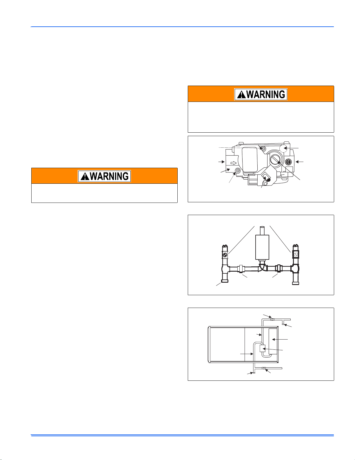
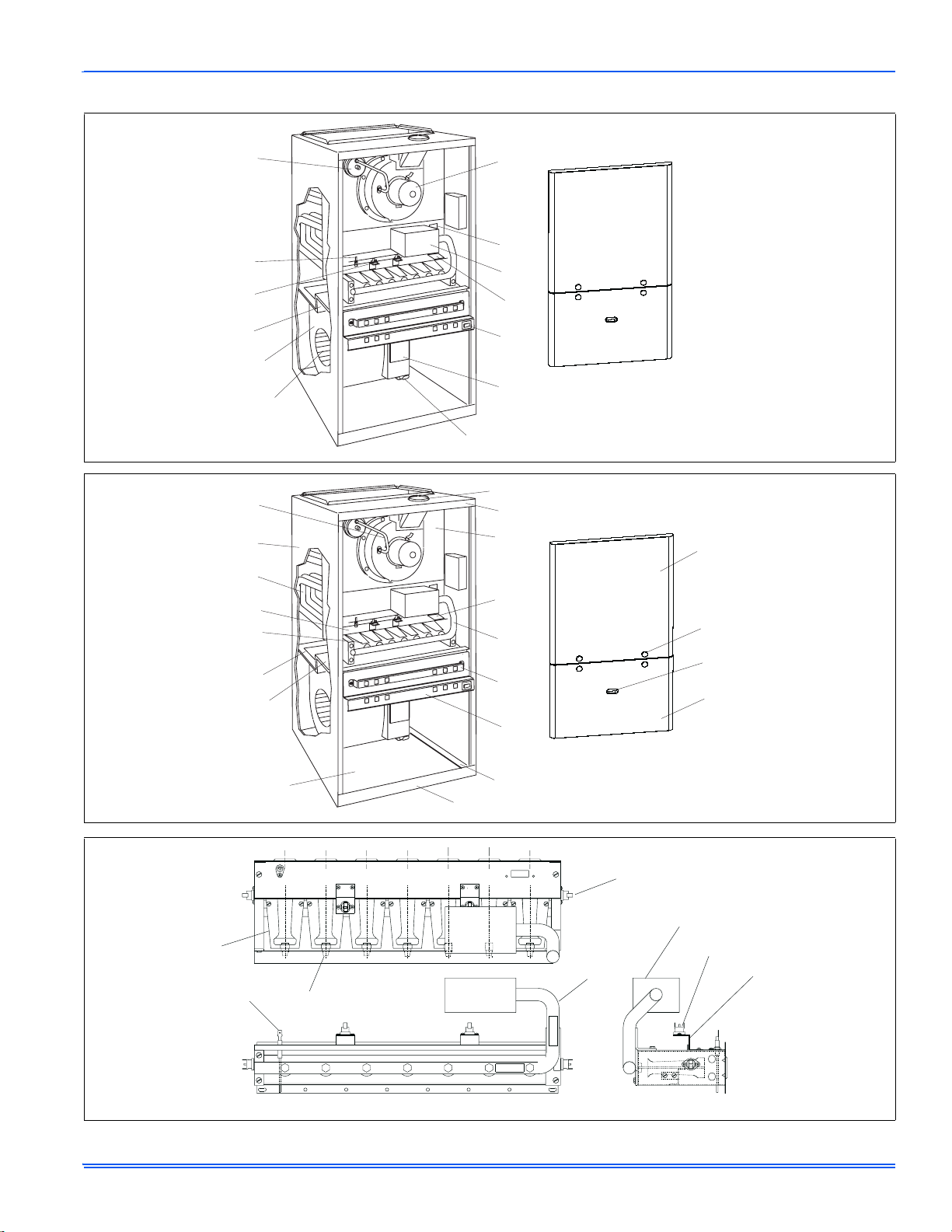
2. Remove the blower and burner compartment access doors. Dis-
connect the gas supply piping at the union to permit removal of the
entire burner and gas control assembly from the vestibule panel.
Use the wrench boss on the gas valve when removing or installing
this piping. See Figure 4.
3. Unplug the igniter from the wire harness. Disconnect sensor and
rollout switch wires located on top of the air shield. Identify and
note the location of all leads for ease of reinstallation. Also discon-
nect the wires at the side rollout switches (upflow only) and the
gas valve wires.
4. Remove the screws holding the burner assembly to the vestibule
panel and remove this assembly. Handle the assembly carefully
since it contains the igniter, which is fragile and easily broken. The
lower portion of the heat exchanger will now be exposed. To clean
the burner assembly, use a vacuum cleaner, or remove the burn-
ers as outlined in burner cleaning, and clean in hot water.
Upper Heat Exchanger Access
1. Perform steps 1-4 above.
2. Disconnect vent piping from the vent motor assembly at the top
panel on the furnace (upflow only). On downflow models, the vent
pipe is secured to the vent motor outlet with a screw. Remove this
screw before proceeding.
3. Unplug the vent motor wires and ground wire. Remove the pres-
sure switch tubing at the top on the vent motor housing.
NOTE: It is recommended that replacement gaskets be available
before removing vent motor.
1. Remove six mounting screws that hold the vent motor to the
restrictor plate. The surface is gasketed and the gasket can be
reused if it is carefully removed. It is necessary to remove this
assembly to gain access to the restrictor plate mounting holes.
The assembly may be vacuumed if cleaning is necessary. If any
vent assembly parts are damaged, replace with an entire new
assembly (except for gaskets).
2. Remove the perimeter screws attaching the restrictor plate assem-
bly to the vestibule panel. The surface is also gasketed. The
assembly, including the flue baffle plate (rear) may be vacuumed
or cleaned with hot water if necessary.
3. The upper portion of the heat exchanger is now accessible. With a
long flexible wire brush, clean inside each tube at both the top and
bottom. The brush must pass around the rear heat exchanger
tubes. Vacuum loose scale and dirt from each tube.
4. Clean - Replace all components in reverse order. Re-gasket all
surfaces which required a gasket. Reconnect all wiring. Reattach
vent pipe and gas supply lines before restoring service to furnace.
Restore electrical power, check gas supply piping for leaks, and
then verify furnace operation.
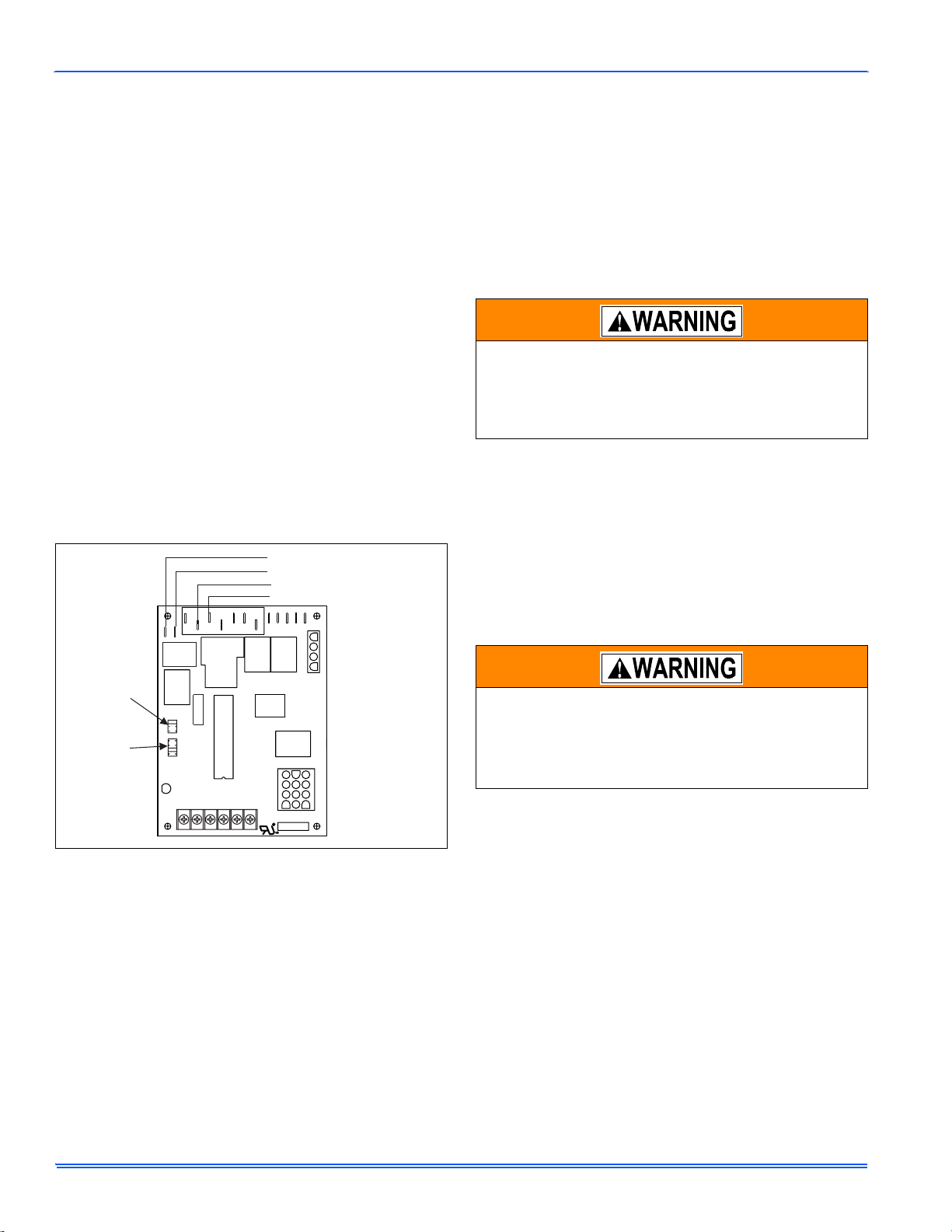
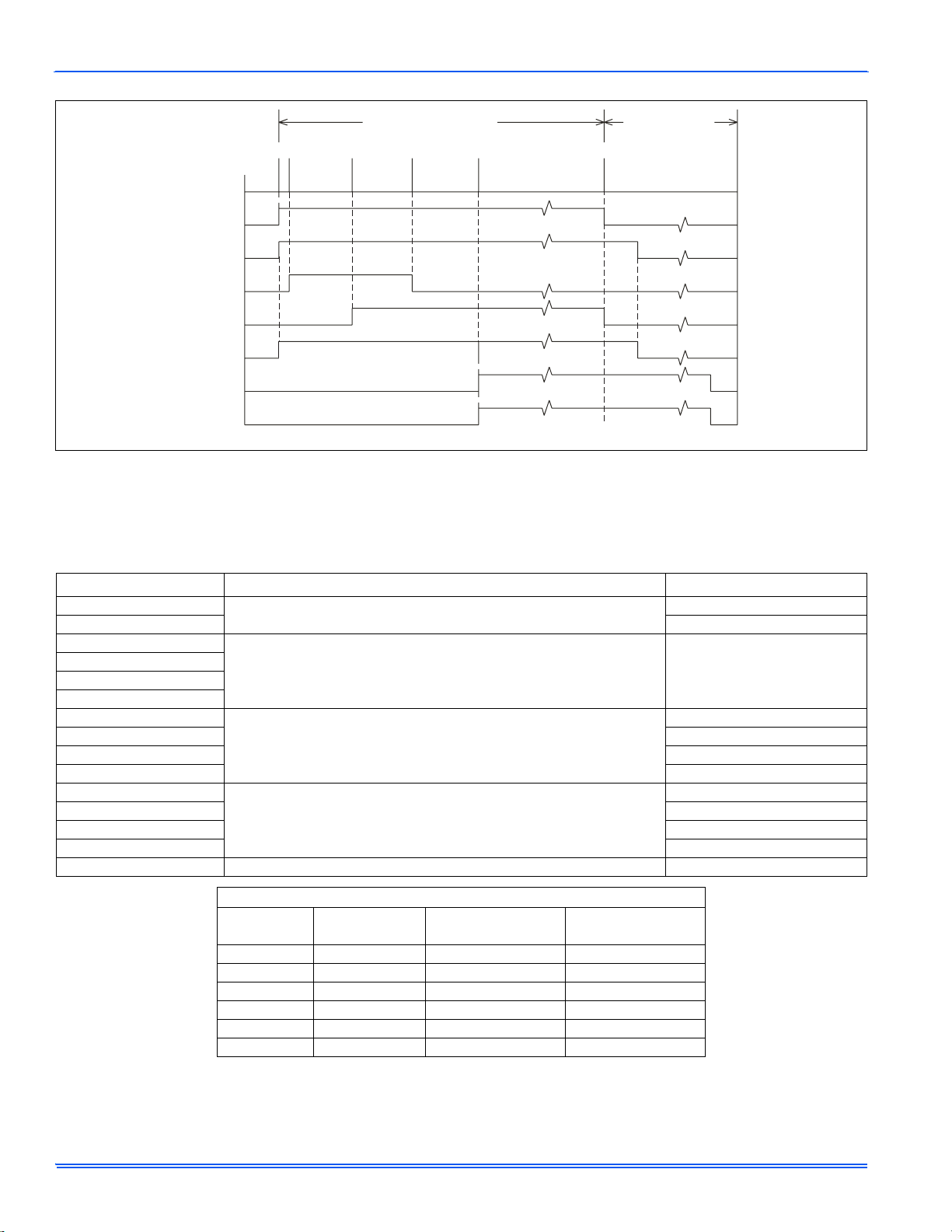
SEQUENCE OF OPERATION
The following describes the sequence of operation of the furnace. Refer
to Figure 1 for component location.
Continuous Blower
Cooling/heating thermostats have a fan switch that has an ON and
AUTO position. In the ON position the thermostat circuit is completed
between terminals R and G. The motor will operate on the speed tap
selected on the Continuous Fan speed Jumper on the control board (HI
COOL, LO COOL, or HEAT pins).
ELECTRIC SHOCK, FIRE OR EXPLOSION HAZARD
Failure to follow safety warnings exactly could result in
dangerous operation, serious injury, death or property
damage.
Improper servicing could result in dangerous operation,
serious injury, and death or property damage.
• Before servicing, disconnect all electrical power to the fur-
nace.
• When servicing controls, label all wires prior to disconnect-
ing. Reconnect wires correctly.
• Verify proper operation after servicing.
Label all wires prior to disconnection when servicing
controls. Wiring errors can cause improper and danger-
ous operation. Verify proper operation after servicing.