035-19650-001 Rev. C (0404)
Unitary Products Group 5
Motor Lubrication
The motors in these furnaces are permanently lubricated, and do not
require periodic oiling.
Every time the filters are changed the following items should be visually
inspected:
• Check combustion air and vent pipe for blockage or leakage.
• Check all components to be sure they are in good condition and
that there are no obvious signs of deterioration.
• Check the drain lines to make sure there are no cracks or leaks.
• Check for dirt or lint on any surfaces or on components. Do not try
to clean any of the surfaces or components. Cleaning of the fur-
nace and its components must be done by a qualified service pro-
fessional.
If, during the inspection of your furnace, you find any of the following
conditions:
• Excessive amounts of dust and lint on components.
• Damaged or deteriorated components or surfaces.
• Leaks or blockage in the vent pipe passages.
• Water on any surface inside or outside of the furnace.
Do not operate the furnace, call a certified dealer / servicing contractor
to check and / or clean your furnace, or for more information if you have
questions about the operation of your furnace.
If all components appear to be in good operating condition, replace the
front panels. Turn ON the gas and electrical power supplies to the fur-
nace, and set thermostat to the desired temperature.
SECTION II: SERVICE AND MAINTENANCE
MANUAL
SAFETY SECTION
The following safety rules must be followed when servicing the furnace.
FURNACE MAINTENANCE SECTION
The furnace should be cleaned and adjusted by a certified dealer or
qualified service contractor once a year or before the start of every
heating season. The following items must be cleaned and serviced or
replaced if there are signs of deterioration.
1. The vent terminal screen (if applicable).
2. The furnace vent and combustion air intake passageways. Should
it be necessary to service the vent/air intake system, the manufac-
turer recommends this service be conducted by a qualified service
agency. The operation of this appliance requires the reassembly
and resealing of the vent/air intake system.
3. The furnace burners, ignitor and flame sensor.
4. The condensate collection and disposal system. If any disassem-
bly of components containing flue or vent gases is required, a
qualified service agency must perform the service.
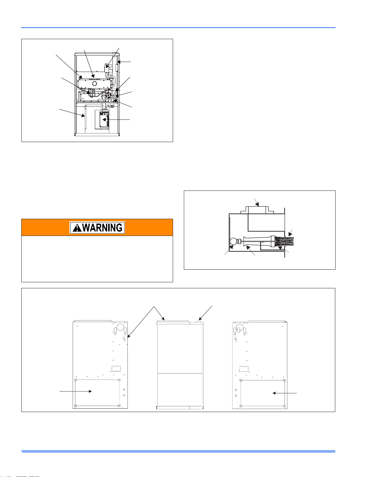
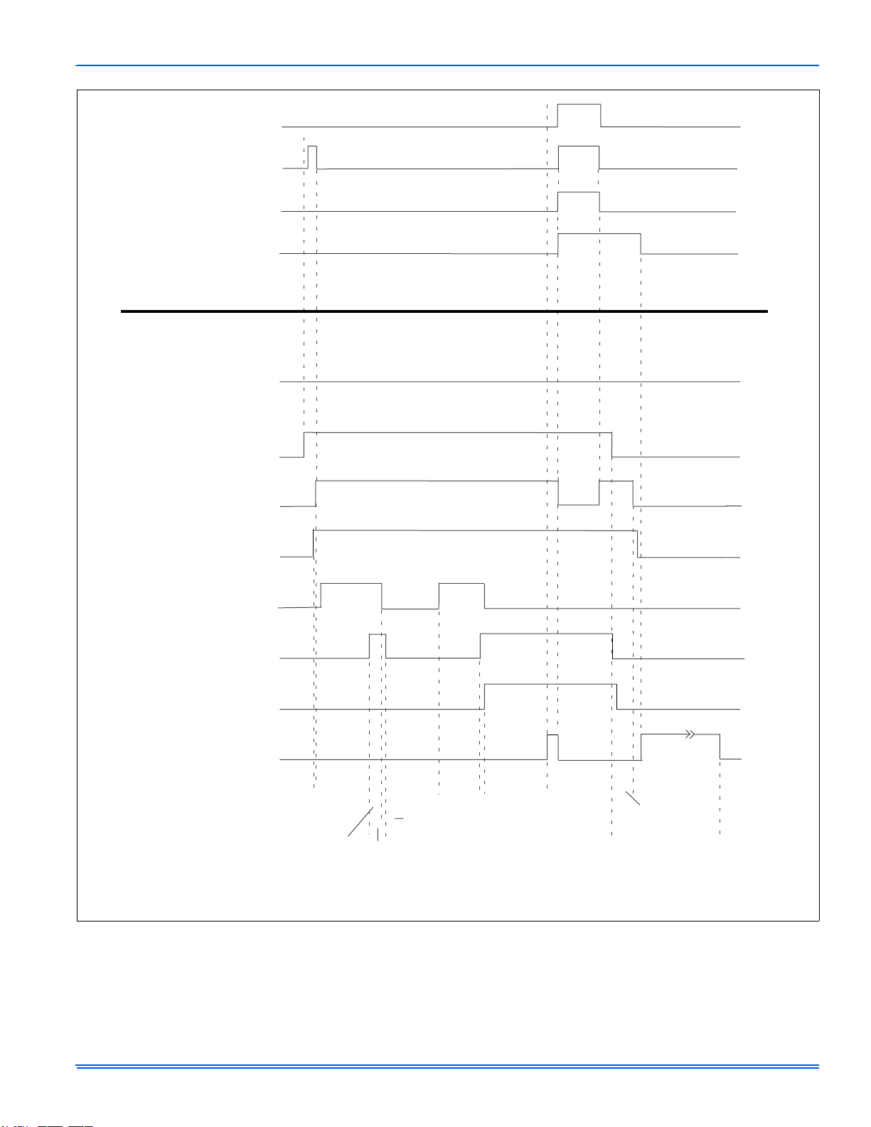
SEQUENCE OF OPERATION
The following describes the sequence of operation of the furnace. Refer
to Figure 1 for component location.
1. Call for 1st stage only
• On a call for 1st stage heat, the thermostat closes a circuit
between R and W1.
• The Microprocessor in the Furnace Control runs a ‘Self Check’.
• The Control checks the Primary Limit, Auxiliary Limit, and Roll-
out Switches for closed contacts.
• The Control checks that the Low Fire Pressure Switch (1LP) is
open.
• The Inducer Motor is energized on high speed, closing the con-
tacts of 1LP.
• The Control checks that 1LP is closed.
• The Inducer is switched to low speed.
• The Igniter is energized for 17 seconds.
• The Gas Valve is energized on 1st Stage (Low Fire).
• Flame Rectification is recognized within 7 seconds.
• 30 seconds after flame is proven, the ‘Heat Low’ relay is ener-
gized providing 120 Volts AC to the Blower Motor.
• At the same time, the EAC and Hum Hot relays are energized,
providing 120 Volts AC to the EAC Hot and Hum Hot terminals.
2. Call for 2nd Stage after 1st Stage is operating
• A call for 2nd Stage can be made by a 2-Stage thermostat, or by
the Second-Stage timer that comes installed in the furnace.
NOTE: When using a 2-Stage thermostat, the Timer should be discon-
nected.
• The Inducer Motor is shifted to high speed by the control, closing
the contacts of 2LP (The High Fire Pressure Switch.).
• The Control checks that 2LP is closed.
• The Gas Valve is energized on 2nd Stage (High Fire).
• The Control simultaneously de-energizes the Heat Low relay
and energizes the Heat High relay, providing 120 Volts AC to a
different speed of the Blower Motor.
3. 2nd Stage is satisfied, 1st Stage still calling.
• If a Single Stage Thermostat and the 2nd Stage Timer are used,
the Furnace will stay on High Fire until the thermostat is satis-
fied.
• When the circuit between R and W2 is opened, the Control
switches the Inducer Motor to low speed, causing the contacts of
2LP to open.
• When 2LP opens, 2nd Stage of the Gas Valve is de-energized.
• 30 seconds later, the Control switches the Blower from Heat
High to Heat Low.
4. 1st Stage Satisfied
• The Thermostat opens the circuit between R and W1
• Immediately the Gas Valve is de-energized and Flame Rectifica-
tion is lost.
• The Inducer Motor is de-energized after a 15 second Post Purge
and the Hum Hot terminal is de-energized.
• The ‘Fan Off Delay’ circuit is initiated. The Delay time can be
field set at 60, 90, 120, or 180 seconds. It comes from the fac-
tory set at 60 seconds.
• The Heat Low terminal is de-energized; stopping the Blower and
the EAC terminal is de-energized.
5. 1st and 2nd Stage called simultaneously
• The 1st stage call is processed as described in paragraph 1
above.
• Once Flame Rectification is established, 2nd Stage is entered
immediately as described in paragraph 2 above.
ELECTRIC SHOCK, FIRE OR EXPLOSION HAZARD
Failure to follow safety warnings exactly could result in
dangerous operation, serious injury, death or property
damage.
Improper servicing could result in dangerous operation,
serious injury, and death or property damage.
• Before servicing, disconnect all electrical power to the fur-
nace.
• When servicing controls, label all wires prior to discon-
necting. Reconnect wires correctly.
• Verify proper operation after servicing.