York PS9 User manual

105564-UIM-A-0205
HIGH EFFICIENCY
TUBULAR HEAT EXCHANGER SERIES
MODELS: PS9 / FC9S / FL9S
(Single Stage Upflow)
40 - 135 MBH INPUT
(11.7 - 39.6 KW) INPUT
INSTALLATION MANUAL
EFFICIENCY
RATING
CERTIFIED
ISO 9001
Certified Quality
Management System
SECTION I: SAFETY
This is a safety alert symbol. When you see this symbol on
labels or in manuals, be alert to the potential for personal
injury.
Understand and pay particular attention to the signal words DANGER,
WARNING, or CAUTION.
DANGER indicates an imminently hazardous situation, which, if not
avoided, will result in death or serious injury.
WARNING indicates a potentially hazardous situation, which, if not
avoided, could result in death or serious injury.
CAUTION indicates a potentially hazardous situation, which, if not
avoided may result in minor or moderate injury. It is also used to
alert against unsafe practices and hazards involving only property dam-
age.
Improper installation may create a condition where the operation of
the product could cause personal injury or property damage.
Improper installation, adjustment, alteration, service or mainte-
nance can cause injury or property damage. Refer to this manual
for assistance or for additional information, consult a qualified con-
tractor, installer or service agency.
This product must be installed in strict compliance with the installa-
tion instructions and any applicable local, state, and national codes
including, but not limited to building, electrical, and mechanical
codes.
LIST OF SECTIONS
SAFETY . . . . . . . . . . . . . . . . . . . . . . . . . . . . . . . . . . . . . . . . . . . . . . . . 1
DUCTWORK . . . . . . . . . . . . . . . . . . . . . . . . . . . . . . . . . . . . . . . . . . . . 3
FILTERS . . . . . . . . . . . . . . . . . . . . . . . . . . . . . . . . . . . . . . . . . . . . . . . 6
GAS PIPING . . . . . . . . . . . . . . . . . . . . . . . . . . . . . . . . . . . . . . . . . . . . 6
ELECTRICAL POWER . . . . . . . . . . . . . . . . . . . . . . . . . . . . . . . . . . . . 8
TWINNING AND STAGING . . . . . . . . . . . . . . . . . . . . . . . . . . . . . . . . . 9
COMBUSTION AIR AND VENT SYSTEM . . . . . . . . . . . . . . . . . . . . .11
CONDENSATE PIPING . . . . . . . . . . . . . . . . . . . . . . . . . . . . . . . . . . .18
SAFETY CONTROLS . . . . . . . . . . . . . . . . . . . . . . . . . . . . . . . . . . . .18
START-UP AND ADJUSTMENTS . . . . . . . . . . . . . . . . . . . . . . . . . . .19
WIRING DIAGRAM . . . . . . . . . . . . . . . . . . . . . . . . . . . . . . . . . . . . . .25
LIST OF FIGURES
Dimensions . . . . . . . . . . . . . . . . . . . . . . . . . . . . . . . . . . . . . . . . . . . . .5
Furnace Base Rectangular Blockoff Panel . . . . . . . . . . . . . . . . . . . . . 6
Gas Valve . . . . . . . . . . . . . . . . . . . . . . . . . . . . . . . . . . . . . . . . . . . . . . .6
Gas Piping . . . . . . . . . . . . . . . . . . . . . . . . . . . . . . . . . . . . . . . . . . . . . . 6
Electrical Wiring . . . . . . . . . . . . . . . . . . . . . . . . . . . . . . . . . . . . . . . . . .8
Line Wiring Connections . . . . . . . . . . . . . . . . . . . . . . . . . . . . . . . . . . .9
Single Stage Heat Thermostat Connections . . . . . . . . . . . . . . . . . . . .9
Single Stage Heating and Two-Stage Cooling
Thermostat Connections . . . . . . . . . . . . . . . . . . . . . . . . . . . . . . . . . . .9
Accessory Connections . . . . . . . . . . . . . . . . . . . . . . . . . . . . . . . . . . . .9
Typical Twinned Furnace Application . . . . . . . . . . . . . . . . . . . . . . . .10
Single Stage Twinning Wiring Diagram . . . . . . . . . . . . . . . . . . . . . . . 10
Two-Stage Twinning Wiring Diagram . . . . . . . . . . . . . . . . . . . . . . . . .11
Home Layout . . . . . . . . . . . . . . . . . . . . . . . . . . . . . . . . . . . . . . . . . . .13
Termination Configuration - 1 Pipe . . . . . . . . . . . . . . . . . . . . . . . . . .14
Termination Configuration - 2 Pipe . . . . . . . . . . . . . . . . . . . . . . . . . . .14
Termination Configuration - 2 Pipe Basement . . . . . . . . . . . . . . . . . .14
Double Horizontal Sealed Combustion Air and Vent Termination . . .15
Double Vertical Sealed Combustion Air and Vent Termination . . . . .15
Sealed Combustion Air Intake Connection and Vent Connection . . .15
Combustion Airflow Path Through The Furnace Casing . . . . . . . . . .15
Outside and Ambient Combustion Air . . . . . . . . . . . . . . . . . . . . . . . . .17
Attic and Crawl Space Combustion Air Termination . . . . . . . . . . . . . .18
Condensate Piping . . . . . . . . . . . . . . . . . . . . . . . . . . . . . . . . . . . . . . .18
Pressure Switch Tube Routing . . . . . . . . . . . . . . . . . . . . . . . . . . . . . .19
Gas Valve . . . . . . . . . . . . . . . . . . . . . . . . . . . . . . . . . . . . . . . . . . . . . .21
Reading Gas Pressure . . . . . . . . . . . . . . . . . . . . . . . . . . . . . . . . . . . .22
Typical Heat/Cool Speed Tap Connections . . . . . . . . . . . . . . . . . . . .22
Wiring Diagram . . . . . . . . . . . . . . . . . . . . . . . . . . . . . . . . . . . . . . . . . .25
LIST OF TABLES
Unit Clearances to Combustibles . . . . . . . . . . . . . . . . . . . . . . . . . . . . .3
Minimum Duct Sizing For Proper Airflow . . . . . . . . . . . . . . . . . . . . . . .4
Round Duct Size . . . . . . . . . . . . . . . . . . . . . . . . . . . . . . . . . . . . . . . . . 4
Filter Sizes . . . . . . . . . . . . . . . . . . . . . . . . . . . . . . . . . . . . . . . . . . . . . .6
High Altitude Conversion (40-120 MBTUH Models) . . . . . . . . . . . . . . .7
High Altitude Conversion (135 MBTUH Models) . . . . . . . . . . . . . . . . .7
Electrical and Performance Data . . . . . . . . . . . . . . . . . . . . . . . . . . . . .8
Combustion Air Intake and Vent Connection Size at Furnace
(All Models) . . . . . . . . . . . . . . . . . . . . . . . . . . . . . . . . . . . . . . . . . . . .11
Combustion Air Supply and Vent Piping . . . . . . . . . . . . . . . . . . . . . . .12
Estimated Free Area . . . . . . . . . . . . . . . . . . . . . . . . . . . . . . . . . . . . . .16
Free Area . . . . . . . . . . . . . . . . . . . . . . . . . . . . . . . . . . . . . . . . . . . . . .16
Unconfined Space Minimum Area in Square Inch . . . . . . . . . . . . . . .16
Inlet Gas Pressure Range . . . . . . . . . . . . . . . . . . . . . . . . . . . . . . . . .21
Nominal Manifold Pressure . . . . . . . . . . . . . . . . . . . . . . . . . . . . . . . . .21
Blower Performance CFM . . . . . . . . . . . . . . . . . . . . . . . . . . . . . . . . .23
Filter Performance - Pressure Drop Inches W.C. and (kPa) . . . . . . . .23

105564-UIM-A-0205
2Unitary Products Group
SPECIFIC SAFETY RULES AND PRECAUTIONS
1. Only Natural gas or Propane (LP) gas are approved for use with
this furnace. Refer to the furnace rating plate or Section IV of
these instructions.
2. Install this furnace only in a location and position as specified in
SECTION I of these instructions.
3. A gas-fired furnace for installation in a residential garage must be
installed as specified in SECTION I of these instructions.
4. Provide adequate combustion and ventilation air to the furnace
space as specified in SECTION VI of these instructions.
5. Combustion products must be discharged outdoors. Connect this
furnace to an approved vent system only, as specified in SEC-
TION VI of these instructions.
6. Tests for gas leaks as specified in SECTION XI of these instruc-
tions.
7. Always install the furnace to operate within the furnace’s intended
temperature rise range. Only connect the furnace to a duct system
which has an external static pressure within the allowable range,
as specified on the furnace rating plate.
8. When a furnace is installed so that supply ducts carry air circulated
by the furnace to areas outside the space containing the furnace,
the return air shall also be handled by duct(s) sealed to the fur-
nace casing and terminating outside the space containing the fur-
nace.
9. The furnace is not to be used for temporary heating of buildings or
structures under construction.
10. When installed in a Non-HUD-Approved Modular Home or building
constructed on-site, combustion air shall not be supplied from
occupied spaces.
11. The size of the unit should be based on an acceptable heat loss
calculation for the structure. ACCA, Manual J or other approved
methods may be used.
SAFETY REQUIREMENTS
• This furnace should be installed in accordance with all national
and local building/safety codes and requirements, local plumbing
or wastewater codes, and other applicable codes. In the absence
of local codes, install in accordance with the National Fuel Gas
Code ANSI Z223.1/NFPA 54, National Fuel Gas Code, and/or
CAN/CGA B149.1 Natural Gas and Propane Installation Code
(latest editions). Furnaces have been certified to the latest edition
of standard ANSI Z21-47 • CSA 2.3.
• Refer to the unit rating plate for the furnace model number, and
then see the dimensions page of this instruction for return air ple-
num dimensions in Figure 1. The plenum must be installed
according to the instructions.
• Provide clearances from combustible materials as listed under
Clearances to Combustibles in Table 1.
• Provide clearances for servicing ensuring that service access is
allowed for both the burners and blower.
• These models ARE NOT CSA listed or approved for installation
into a HUD Approved Modular Home or a Manufactured
(Mobile) Home.
• This furnace is not approved for installation in trailers or recre-
ational vehicles.
• Failure to carefully read and follow all instructions in this
manual can result in furnace malfunction, death, personal
injury and/or property damage.
• Furnaces for installation on combustible flooring shall not be
installed directly on carpeting, tile or other combustible material
other than wood flooring.
• Check the rating plate and power supply to be sure that the elec-
trical characteristics match. All models use nominal 115 VAC, 1
Phase, 60-Hertz power supply. DO NOT CONNECT THIS APPLI-
ANCE TO A 50 HZ POWER SUPPLY OR A VOLTAGE ABOVE
130 VOLTS.
• Furnace shall be installed so the electrical components are pro-
tected from water.
• Installing and servicing heating equipment can be hazardous due
to the electrical components and the gas fired components. Only
trained and qualified personnel should install, repair, or service
gas heating equipment. Untrained service personnel can perform
basic maintenance functions such as cleaning and replacing the
air filters. When working on heating equipment, observe precau-
tions in the manuals and on the labels attached to the unit and
other safety precautions that may apply.
• These instructions cover minimum requirements and conform to
existing national standards and safety codes. In some instances
these instructions exceed certain local codes and ordinances,
especially those who have not kept up with changing residential
and non-HUD modular home construction practices. These
instructions are required as a minimum for a safe installation.
COMBUSTION AIR QUALITY
(LIST OF CONTAMINANTS)
The furnace will require OUTDOOR AIR for combustion when the fur-
nace is located in any of the following environments.
• Restricted Environments
• Commercial buildings
• Buildings with indoor pools
• Furnaces installed in laundry rooms
• Furnaces installed in hobby or craft rooms
• Furnaces installed near chemical storage areas
• Chemical Exposure
The furnace will require OUTDOOR AIR for combustion when the fur-
nace is located in an area where the furnace is being exposed to the fol-
lowing substances and / or chemicals.
• Permanent wave solutions
• Chlorinated waxes and cleaners
• Chlorine based swimming pool chemicals
• Water softening chemicals
• De-icing salts or chemicals
• Carbon tetrachloride
• Halogen type refrigerants
• Cleaning solvents (such as perchloroethylene)
• Printing inks, paint removers, varnishes, etc.
• Hydrochloric acid
• Cements and glues
• Antistatic fabric softeners for clothes dryers
• Masonry acid washing materials
When outdoor air is used for combustion, the combustion air intake pipe
termination must be located external to the building and in an area
where there will be no exposure to the substances listed above.
FIRE OR EXPLOSION HAZARD
Failure to follow the safety warnings exactly could result in serious
injury, death or property damage.
Never test for gas leaks with an open flame. Use a commercially
available soap solution made specifically for detection of leaks to
check all connections. A fire or explosion may result causing prop-
erty damage, personal injury or loss of life.

105564-UIM-A-0205
Unitary Products Group 3
INSPECTION
As soon as a unit is received, it should be inspected for possible dam-
age during transit. If damage is evident, the extent of the damage
should be noted on the carrier’s freight bill. A separate request for
inspection by the carrier’s agent should be made in writing. Also, before
installation the unit should be checked for screws or bolts, which may
have loosened in transit. There are no shipping or spacer brackets
which need to be removed.
FURNACE LOCATION AND CLEARANCES
The furnace shall be located using the following guidelines:
1. Where a minimum amount of air intake/vent piping and elbows will
be required.
2. As centralized with the air distribution as possible.
3. Where adequate combustion air will be available (particularly
when the appliance is not using outdoor combustion air).
4. Where it will not interfere with proper air circulation in the confined
space.
5. Where the outdoor combustion air/vent terminal will not be blocked
or restricted. Refer to “COMBUSTION AIR / VENT CLEAR-
ANCES” located in SECTION VII of these instructions. These min-
imum clearances must be maintained in the installation.
6. Where the unit will be installed in a level position with no more
than 1/4” (6.4 mm) slope side-to-side and front-to-back to provide
proper condensate drainage.
Installation in freezing temperatures:
1. Furnace shall be installed in an area where ventilation facilities
provide for safe limits of ambient temperature under normal oper-
ating conditions. Ambient temperatures must not fall below 32°F
(0°C) unless the condensate system is protected from freezing.
2. Do not allow return air temperature to be below 55º F (13° C) for
extended periods. To do so may cause condensation to occur in
the main heat exchanger, leading to premature heat exchanger
failure.
3. If this furnace is installed in any area where the ambient tempera-
ture may drop below 32° F (0° C), a UL listed self-regulated heat
tape must be installed on any condensate drain lines. It is required
that self regulating heat tape rated at 3 watts per foot be used.
This must be installed around the condensate drain lines in the
unconditioned space. Always install the heat tape per the manu-
facturer's instructions. Cover the self-regulating heat tape with
fiberglass, Armaflex or other heat resistant insulating material.
4. If this unit is installed in an unconditioned space and an extended
power failure occurs, there will be potential damage to the conden-
sate trap, drain lines and internal unit components. Following a
power failure situation, do not operate the unit until inspection and
repairs are performed.
Clearances for access:
Ample clearances should be provided to permit easy access to the unit.
The following minimum clearances are recommended:
1. Twenty-four (24) inches (61 cm) between the front of the furnace
and an adjacent wall or another appliance, when access is
required for servicing and cleaning.
2. Eighteen (18) inches (46 cm) at the side where access is required
for passage to the front when servicing or for inspection or
replacement of flue/vent connections.
In all cases, accessibility clearances shall take precedence over clear-
ances for combustible materials where accessibility clearances are
greater.
Installation in a residential garage:
1. A gas-fired furnace for installation in a residential garage must be
installed so the burner(s) and the ignition source are located not
less than 18 inches (46 cm) above the floor, and the furnace must
be located or protected to avoid physical damage by vehicles.
SECTION II: DUCTWORK
DUCTWORK GENERAL INFORMATION
The duct system’s design and installation must:
1. Handle an air volume appropriate for the served space and within
the operating parameters of the furnace specifications.
2. Be installed in accordance with standards of NFPA (National Fire
Protection Association) as outlined in NFPA pamphlets 90A and
90B (latest editions) or applicable national, provincial, or state, and
local fire and safety codes.
3. Create a closed duct system. For residential and Non-HUD Modu-
lar Home installations, when a furnace is installed so that the sup-
ply ducts carry air circulated by the furnace to areas outside the
space containing the furnace, the return air shall also be handled
by a duct(s) sealed to the furnace casing and terminating outside
the space containing the furnace.
4. Complete a path for heated or cooled air to circulate through the
air conditioning and heating equipment and to and from the condi-
tioned space.
When the furnace is used in conjunction with a cooling coil, the coil
must be installed parallel with, or in the supply air side of the furnace to
avoid condensation in the primary heat exchanger. When a parallel flow
arrangement is used, dampers or other means used to control airflow
must be adequate to prevent chilled air from entering the furnace. If
manually operated, the damper must be equipped with means to pre-
vent the furnace or the air conditioner from operating unless the damper
is in full heat or cool position.
The furnace area must not be used as a broom closet or for any
other storage purposes, as a fire hazard may be created. Never
store items such as the following on, near or in contact with the fur-
nace.
1. Spray or aerosol cans, rags, brooms, dust mops, vacuum
cleaners or other cleaning tools.
2. Soap powders, bleaches, waxes or other cleaning com-
pounds; plastic items or containers; gasoline, kerosene, ciga-
rette lighter fluid, dry cleaning fluids or other volatile fluid.
3. Paint thinners and other painting compounds.
4. Paper bags, boxes or other paper products
Never operate the furnace with the blower door removed. To
do so could result in serious personal injury and/or equipment
damage.
Improper installation in an ambient below 32ºF (0.0° C) could create
a hazard, resulting in damage, injury or death.
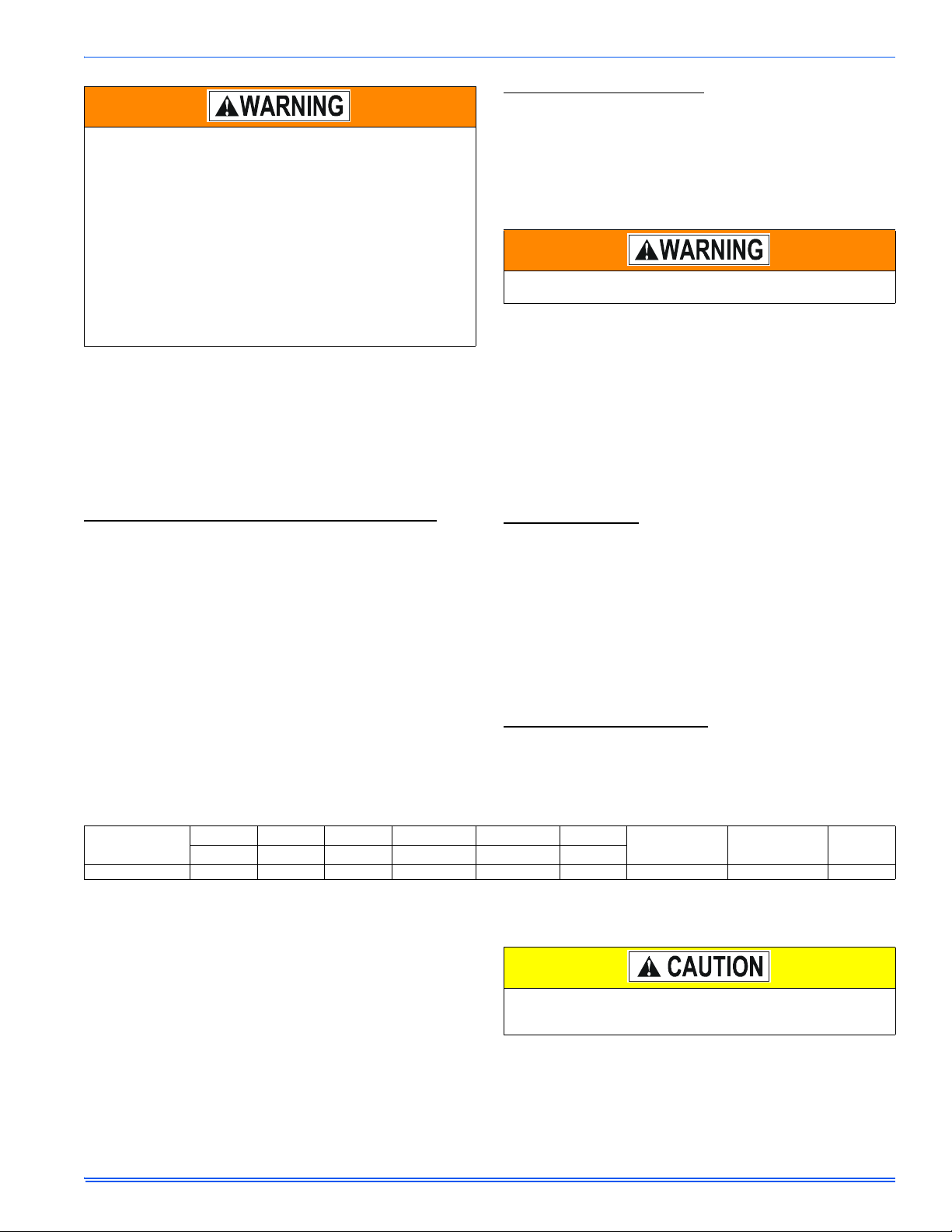
TABLE 1:
Unit Clearances to Combustibles
APPLICATION TOP FRONT REAR LEFT SIDE RIGHT SIDE FLUE FLOOR/
BOTTOM CLOSET
ALCOVE ATTIC
In. (mm) In. (mm) In. (mm) In. (mm) In. (mm) In. (mm)
UPFLOW 1 (25.4) 3 0 (0) 0 (0) 0 (0) 0 (0) COMBUSTIBLE YES YES
The cooling coil must be installed in the supply air duct, down-
stream of the furnace. Cooled air may not be passed over the heat
exchanger.

105564-UIM-A-0205
4Unitary Products Group
DUCTWORK INSTALLATION AND SUPPLY PLENUM
CONNECTION
A proper Heat Loss/Gain Calculation should be done on all
installations for proper application of equipment. From this
the ductwork sizing can be calculated, ACCA Manual J and
D and industry standards are helpful.
Attach the supply plenum to the furnace or coil outlet duct
connection flanges. This is typically through the use of S
cleat material when a metal plenum is used. The use of an
approved flexible duct connector is recommended on all installations to
prevent noise transmission. All connections should be sealed to prevent
air leakage. Sheet metal should be crosshatched to eliminate any pop-
ping when the indoor fan is energized.
When replacing an existing furnace, if the existing supply plenum is not
the same size as the new furnace then the existing plenum must be
removed and a new plenum installed that is of the proper size for the
new furnace. The minimum plenum height is 12” (30 cm). If the plenum
is shorter than 12” (30 cm) the turbulent air flow may cause the limit
controls not to operate as designed if at all.
The duct system is a very important part of the installation. If the duct
system is improperly sized the furnace will not operate properly.
The ducts attached to the furnace plenum should be of sufficient size so
that the furnace operates at the specified external static pressure and
within the air temperature rise specified on the nameplate.
Table 2 is a guide for determining whether the rectangular duct system
that the furnace is being connected to be of sufficient size for proper fur-
nace operation.
Use the Example below to help you in calculating the duct area to deter-
mine whether the ducts have sufficient area so that the furnace oper-
ates at the specified external static pressure and within the air
temperature rise specified on the nameplate.
The following are general duct sizing guidelines that may not serve to
requirements of every application.
Example: The furnace input is 80,000 BTUH, 1,200 CFM blower
requirement. The recommended duct area is 216 sq.in, there are two 8
x 12 rectangular ducts attached to the plenum and there are two 7 inch
round ducts attached to the furnace.
1. Take 8 x 12, which equals 96 square inch x 2 = 192 square inches
then go to round duct size located in Table 3.
2. The square inch area for 7 inch round ducts, 38.4 square inch x 2
= 76.8 square inches,
3. Then take the 192 square inch from the rectangular duct and add it
to the 76.8 square inch of round duct. The total square inch of duct
attached to the furnace supply plenum is 268.8 square inches.
This exceeds the recommended 216 square inch of duct.
In this example, the duct system attached to the plenum has a sufficient
area so that the furnace operates at the specified external static pres-
sure and within the air temperature rise specified on the nameplate.
Providing the return duct is properly sized as well.
1. The Air Temperature Rise is determined by subtracting the Return
Air Temperature Reading from the Supply Air Temperature Read-
ing.
2. The External Static Pressure is determined by adding the Supply
Duct Static Pressure reading to the Return Duct Static Pressure
reading and adding the pressure drop across any applied coil.
TABLES 2 AND 3 are to be used as a guide only to help the installer
determine if the duct sizes are large enough to obtain the proper air flow
(CFM) through the furnace. TABLES 2 and 3 ARE NOT to be used to
design ductwork for the building where the furnace is being installed.
There are several variables associated with proper duct sizing that are
not included in the tables. To properly design the ductwork for the build-
ing, Refer to the ASHRAE Fundamentals Handbook, Chapter on
“DUCT DESIGN” or a company that specializes in Residential and Mod-
ular Home duct designs.
IMPORTANT: The minimum plenum height is 12” (30 cm). The furnace
will not operate properly on a shorter plenum height. The minimum rec-
ommended rectangular duct height is 4” (10 cm) attached to the ple-
num.
IMPORTANT: The air temperature rise should be taken only after the
furnace has been operating for at least 15 minutes. Temperatures and
external static pressures should be taken 6” (15 cm) past the first bend
from the furnace in the supply duct and the return duct. If an external fil-
ter box or an electronic air cleaner is installed, take the return air read-
ings before the filter box or air cleaner.
The duct system must be properly sized to obtain the correct airflow
for the furnace size that is being installed.
Refer to Table 7 and the furnace rating plate for the correct rise
range and static pressures
If the ducts are undersized, the result will be high duct static pres-
sures and/or high temperature rises which can result in a heat
exchanger OVERHEATING CONDITION. This condition can result
in premature heat exchanger failure, which can result in personal
injury, property damage, or death.
TABLE 2:
Minimum Duct Sizing For Proper Airflow
Input/Cabinet Nominal Airflow Return1Rectangular2Round2Supply3Rectangular2Round2
MBTU/H (kW) CFM (m³) In² (cm²) in. x in. (cm x cm) in. (cm) dia. In² (cm²) in. x in. (cm x cm) in. (cm) dia.
40/A (11.7) 1,200 (33.98) 280 (711) 14 x 20 (35.6 x 50.8) 18 (45.7) 216 (549) 12 x 18 (30.5 x 45.7) 16 (40.6)
60/B (17.6) 1,200 (33.98) 280 (711) 14 x 20 (35.6 x 50.8) 18 (45.7) 216 (549) 12 x 18 (30.5 x 45.7) 16 (40.6)
80/B (23.4) 1,200 (33.98) 280 (711) 14 x 20 (35.6 x 50.8) 18 (45.7) 216 (549) 12 x 18 (30.5 x 45.7) 16 (40.6)
80/C (23.4) 1,600 (45.31) 360 (914) 18 x 20 (45.7 x 50.8) 22 (55.8) 280 (711) 14 x 20 (35.6 x 50.8) 18 (45.7)
80/C (23.4) 2,000 (56.63) 440 (1,118) 20 x 22 (50.8 x 55.8) 24 (60.9) 390 (991) 16 x 22 (40.6 x 55.8) 22 (55.8)
100/C (29.3) 1,600 (45.31) 360 (914) 18 x 20 (45.7 x 50.8) 22 (55.8) 280 (711) 14 x 20 (35.6 x 50.8) 18 (45.7)
100/C (29.3) 2,000 (56.63) 440 (1,118) 20 x 22 (50.8 x 55.8) 24 (60.9) 390 (991) 16 x 22 (40.6 x 55.8) 22 (55.8)
120/D (35.2) 2,000 (56.63) 440 (1,118) 20 x 22 (50.8 x 55.8) 24 (60.9) 390 (991) 16 x 22 (40.6 x 55.8) 22 (55.8)
135/D (39.6) 2,000 (56.63) 440 (1,118) 20 x 22 (50.8 x 55.8) 24 (60.9) 390 (991) 16 x 22 (40.6 x 55.8) 22 (55.8)
NOTE: This chart does not replace proper duct sizing calculations or take into account static pressure drop for run length and fittings. Watch out for the temperature rise and static pres-
sures.
1. Maximum return air velocity in rigid duct @ 700 feet per minute (19.82 m3/ minute).
2. Example return main trunk duct minimum dimensions.
3. Maximum supply air velocity in rigid duct @ 900 feet per minute (25.49 m3/ minute).
TABLE 3:
Round Duct Size
Round Duct Size Calculated Area For Each Round Duct Size
inches (cm) Sq.in (cm2)
5 (13) 19.6 (126)
6 (15) 28.2 (182)
7 (18) 38.4 (248)
8 (20) 50.2 (324)
9 (23) 63.6 (410)
10 (25) 78.5 (506)
11 (28) 95 (613)
12 (30) 113.1 (730)
13 (33) 132.7 (856)
14 (36) 153.9 (993)

105564-UIM-A-0205
Unitary Products Group 5
If a matching cooling coil is used, it may be placed directly on the fur-
nace outlet and sealed to prevent leakage. Follow the coil instructions
for installing the supply plenum. On all installations without a coil, a
removable access panel is recommended in the outlet duct such that
smoke or reflected light would be observable inside the casing to indi-
cate the presence of leaks in the heat exchanger. This access cover
shall be attached in such a manner as to prevent leaks.
RESIDENTIAL AND NON HUD MODULAR HOME
RETURN PLENUM CONNECTION
Return air may enter the furnace through the side(s) or bottom depend-
ing on the type of application. Return air may not be connected into the
rear panel of the unit. In order to stay within the velocity rating of the fil-
ter(s), it is recommended that applications over 1800 CFM (57 m³/min)
use return air from two sides, one side and the bottom or bottom only.
For single return application, see data and notes on blower perfor-
mance data tables in this manual.
BOTTOM RETURN AND ATTIC INSTALLATIONS
Bottom return applications normally pull return air through a base plat-
form or return air plenum. Be sure the return platform structure or return
air plenum is suitable to support the weight of the furnace.
The furnace base is equipped with a rectangular blockoff panel that can
be removed by performing the following steps:
1. Lay the furnace on its back.
2. Remove the toe plate. See Figure 2.
3. Slide the blockoff panel out and then replace the toe plate.
4. Bend the 3/4” flanges that will be used to attach the return air ple-
num using the scribe marks in the furnace base. Refer to Figure 1
“Bottom Image Return End”.
5. Be sure to seal the furnace to plenum connections to prevent air
leakage. Refer to Figure 1 for unit and plenum dimensions.
Attic installations must meet all minimum clearances to combustibles
and have floor support with required service accessibility.
The supply air temperature MUST NEVER exceed the Maximum
Supply Air Temperature, specified on the nameplate.
Operating the furnace above the maximum supply air temperature
will cause the heat exchanger to overheat, causing premature heat
exchanger failure. Improper duct sizing, dirty air filters, incorrect
manifold pressure, incorrect gas orifice and/or a faulty limit switch
can cause the furnace to operate above the maximum supply air
temperature. Refer to sections II and III for additional information on
correcting the problem.
FIGURE 1: Dimensions
30-7/8
21-1/2
13-7/8
7
11
7/8
23-3/4
7/8
30-1/8
26-1/2
24-5/8 A
40
26-1/2
25-3/8
28-3/8
21-1/2
11
8
1-1/2” GAS
PIPE ENTRY
7/8” JUNCTION
BOX HOLE
T-STAT WIRING
7/8” K.O.
CONDENSATE
DRAIN 7/8” K.O.
OPTIONAL RETURN AIR
CUT-OUT (either side)
FOR USE WITH
EXTERNAL FILTER
FRAME
LEFT SIDE
FRONT RIGHT SIDE
26-3/4
1-3/81-1/4
C
24-3/8
20 5/8
5/8
B
24-17/16
2
D
BOTTOM IMAGE
RETURN END TOP IMAGE
SUPPLY END
1-1/2” GAS
PIPE ENTRY
7/8” JUNCTION
BOX HOLE
T-STAT WIRING
7/8” K.O.
CONDENSATE
DRAIN 7/8” K.O.
BTUH (kW)
Input/Output CFM
m3/min) Cabinet
Size Cabinet Dimension Air Intake
A (in.) A (cm) B (in.) B (cm) C (in.) C (cm) D (in.) D (cm)
40/38 (11.7/10.8) 1200 (34.0) A 14-1/2 36.8 13-1/4 33.7 12-1/8 30.8 6-1/4 15.9
60/56 (17.8/16.1) 1200 (34.0) B 17-1/2 44.4 16-1/4 41.3 15-1/8 38.4 8-1/2 21.6
80/74 (12.4/22.0) 1200 (34.0) B 17-1/2 44.4 16-1/4 41.3 15-1/8 38.4 8-1/2 21.6
80/75 (23.4/22.0) 1600 (45.3) C 21 53.3 19-3/4 50.2 18-1/2 47.0 8-7/8 22.5
80/75 (23.4/22.0) 2000 (56.6) C 21 53.3 19-3/4 50.2 18-1/2 47.0 8-7/8 22.5
100/93 (29.3/27.8) 1600 (45.3) C 21 53.3 19-3/4 50.2 18-1/2 47.0 8-7/8 22.5
100/93 (29.3/27.8) 2000 (56.6) C 21 53.3 19-3/4 50.2 18-1/2 47.0 8-7/8 22.5
120/112 (35.1/32.8) 2000 (56.6) D 24-1/2 62.2 23-1/4 59.4 21-7/8 55.6 10-5/8 27.0
135/127 (39.6/36.9) 2000 (56.6) D 24-1/2 62.2 23-1/4 59.4 21-7/8 55.6 10-5/8 27.0

105564-UIM-A-0205
6Unitary Products Group
IMPORTANT: If an external mounted filter rack is being used see the
instructions provided with that accessory for proper hole cut size.
SECTION III: FILTERS
FILTER INSTALLATION
All applications require the use of a filter. A high velocity filter and a side
return filter rack are provided for field installation. Replacement filter
size is shown in Table 4.
Filters must be installed external to the furnace cabinet. DO NOT
attempt to install filters inside the furnace.
SIDE RETURN - FILTER INSTALLATION
Locate and mark the side return opening. Refer to Figure 1 for dimen-
sions of the cutout.
Install the side filter rack following the instructions provided with that
accessory. If a filter(s) is provided at another location in the return air
system, the ductwork may be directly attached to the furnace side
panel.If not provided with the furnace, an accessory filter rack is avail-
able for mounting the filter external to the cabinet.
IMPORTANT: Some accessories such as electronic air cleaners and
pleated media may require a larger side opening. Follow the instruc-
tions supplied with that accessory for side opening requirements. Do
not cut the opening larger than the dimensions shown in Figure 1.
SECTION IV: GAS PIPING
GAS SAFETY
IMPORTANT: Plan your gas supply before determining the correct gas
pipe entry. Use 90-degree service elbow(s), or short nipples and con-
ventional 90-degree elbow(s) to enter through the cabinet access holes.
GAS PIPING INSTALLATION
Properly sized wrought iron, approved flexible or steel pipe must be
used when making gas connections to the unit. If local codes allow the
use of a flexible gas appliance connection, always use a new listed con-
nector. Do not use a connector that has previously serviced another gas
appliance.
Some utility companies or local codes require pipe sizes larger than the
minimum sizes listed in these instructions and in the codes. The furnace
rating plate and the instructions in this section specify the type of gas
approved for this furnace - only use those approved gases. The instal-
lation of a drip leg and ground union is required. Refer to Figure 4.
IMPORTANT: An accessible manual shutoff valve must be installed
upstream of the furnace gas controls and within 6 feet (1.8 m) of the fur-
nace.
The furnace must be isolated from the gas supply piping system by
closing its individual external manual shutoff valve during any pressure
testing of the gas supply piping system at pressures equal to or greater
than 1/2 psig (3.5 kPa).
FIGURE 2: Furnace Base Rectangular Blockoff Panel
TABLE 4:
Filter Sizes
Input/Output
BTU/H (kW) Nominal CFM
(m3/min) Cabinet
Size Side Return
Filter in. (cm) Bottom Return
Filter in. (cm)
40/38
(11.7/10.8) 1200
(34) A16 x 25
(41 x 64) 14 x 25
(36 x 64)
60/56
(17.6/16.1) 1200
(34) B16 x 25
(41 x 64) 16 x 25
(41 x 64)
80/74
(23.4/22.0) 1200
(34) B16 x 25
(41 x 64) 16 x 25
(41 x 64)
80/75
(23.4/22.0) 1600
(45) C16 x 25
(41 x 64) 20 x 25
(51 x 64)
80/75
(23.4/22.0) 2000
(57) C16 x 25
(41 x 64) 20 x 25
(51 x 64)
100/93
(29.3/27.8) 1600
(45) C16 x 25
(41 x 64) 20 x 25
(51 x 64)
100/93
(29.3/27.8) 2000
(57) C16 x 25
(41 x 64) 20 x 25
(51 x 64)
120/112
(35.1/32.8) 2000
(57) D(2) 16 x 25
(2) (41 x 64) 22 x 25
(56 x 64)
135/127
(39.6/36.9) 2000
(57) D(2) 16 x 25
(2) (41 x 64) 22 x 25
(56 x 64)
All installations must have a filter installed.
Toe Plate
Removable Rectangular
Base Panel. An overpressure protection device, such as a pressure regulator,
must be installed in the gas piping system upstream of the furnace
and must act to limit the downstream pressure to the gas valve so it
does not exceed 0.5 PSI {14" w.c. (3.48 kPa)}. Pressures exceed-
ing 0.5 PSI {14” w.c. (3.48 kPa)} at the gas valve will cause damage
to the gas valve, resulting in a fire or explosion or cause damage to
the furnace or some of its components that will result in property
damage and loss of life.
FIGURE 3: Gas Valve
FIGURE 4: Gas Piping
INLET
WRENCH
BOSS
INLET
PRESSURE
PORT
ON
OFF
ON/OFF SWITCH
(Shown in ON position)
MAIN REGULATOR
ADJUSTMENT
OUTLET
OUTLET
PRESSURE
PORT
VENT PORT
EXTERNAL MANUAL
SHUTOFF VALVE
TO GAS
SUPPLY
TO GAS
SUPPLY
GROUNDED JOINT UNION
MAY BE INSTALLED
INSIDE OR OUTSIDE UNIT.
DRIP
LEG

105564-UIM-A-0205
Unitary Products Group 7
Gas piping may be connected from either side of the furnace using any
of the gas pipe entry knockouts on both sides of the furnace. Refer to
Figure 1 dimensions.
The inlet to the gas valve lines up directly with the opening in the left
side of the furnace casing. To line up with the opening in the right side
of the casing, two street ells should be used.
GAS ORIFICE CONVERSION FOR PROPANE (LP)
This furnace is constructed at the factory for natural gas-fired operation,
but may be converted to operate on propane (LP) gas by using a fac-
tory-supplied LP conversion kit. Follow the instructions supplied with
the LP kit. Refer to Table 5 or 6 or the instructions in the propane (LP)
conversion kit for the proper gas orifice size.
HIGH ALTITUDE GAS ORIFICE CONVERSION
This furnace is constructed at the factory for natural gas-fired operation
at 0 – 2,000 ft. (0 m – 610 m) above sea level.
The gas orifices on this furnace must be changed in order to maintain
proper and safe operation when the furnace is installed in a location
where the altitude is greater than 2,000 ft. (610 m) above sea level on
natural gas or the altitude is greater than 4,000 ft. (1219 m) above sea
level on propane (LP) gas. Refer to Table 5 or 6 or the instructions in
the high altitude conversion kit or ANSI Z223.1 NFPA 54 National Fuel
Gas Code or in Canada CAN/CGA-B149.1-00 Natural Gas and Pro-
pane Installation Code for proper orifice size.
HIGH ALTITUDE PRESSURE SWITCH CONVERSION
For installation in locations where the altitude is less than 4,500 feet
(1372 m), it is not required that the pressure switch be changed, pro-
vided the maximum vent/intake pipe lengths are adjusted as shown in
the notes to Table 9. For altitudes above 4,500 feet (137 m), refer to
Instructions in the Accessory High Altitude Kit.
The gas valve body is a very thin casting that cannot take any
external pressure. Never apply a pipe wrench to the body of the gas
valve when installing piping. A wrench must be placed on the octag-
onal hub located on the gas inlet side of the valve. Placing a wrench
to the body of the gas valve will damage the valve causing improper
operation and/or the valve to leak.
TABLE 5:
High Altitude Conversion (40-120 MBTUH Models)
Type
Of Gas Orifice at
Sea Level 2,000 ft.
(610 m) 3,000 ft.
(914 m) 4,000 ft.
(1219 m)
Natural #45 #46 #47 #47
Propane #55 #55 #55 #55
Type
Of Gas 5,000 ft.
(1524 m) 6,000 ft.
(1829 m) 7,000 ft.
(2134 m) 8,000 ft.
(2438 m)
Natural #47 #48 #48 #49
Propane #56 #56 #56 #56
Type
Of Gas 9,000 ft.
(2743 m) 10,000 ft.
(3048 m)
Natural #49 #50
Propane #56 #57
TABLE 6:
High Altitude Conversion (135 MBTUH Models)
Type
Of Gas Orifice at
Sea Level 2,000 ft.
(610 m) 3,000 ft.
(914 m) 4,000 ft.
(1219 m)
Natural #44 #45 #44 #45
Propane #54 #54 #55 #55
Type
Of Gas 5,000 ft.
(1524 m) 6,000 ft.
(1829 m) 7,000 ft.
(2134 m) 8,000 ft.
(2438 m)
Natural #46 #47 #47 #48
Propane #55 #55 #55 #56
Type
Of Gas 9,000 ft.
(2743 m) 10,000 ft.
(3048 m)
Natural #48 #49
Propane #56 #56
PROPANE AND HIGH ALTITUDE CONVERSION KITS
It is very important to choose the correct kit and/or gas orifices for
the altitude and the type of gas for which the furnace is being
installed.
Only use natural gas in furnaces designed for natural gas. Only use
propane (LP) gas for furnaces that have been properly converted to
use propane (LP) gas. Do not use this furnace with butane gas.
Incorrect gas orifices or a furnace that has been improperly con-
verted will create an extremely dangerous condition resulting in pre-
mature heat exchanger failure, excessive sooting, high levels of
carbon monoxide, personal injury, property damage, a fire hazard
and/or death.
High altitude and propane (LP) conversions are required in order
for the appliance to satisfactory meet the application.
An authorized distributor or dealer must make all gas conversions.
In Canada, a certified conversion station or other qualified agency,
using factory specified and/or approved parts, must perform the
conversion.
The installer must take every precaution to insure that the furnace
has been converted to the proper gas orifice size when the furnace
is installed. Do not attempt to drill out any orifices to obtain the
proper orifice size. Drilling out a gas orifice will cause misalignment
of the burner flames, causing premature heat exchanger burnout,
high levels of carbon monoxide, excessive sooting, a fire hazard,
personal injury, property damage and/or death.

105564-UIM-A-0205
8Unitary Products Group
SECTION V: ELECTRICAL POWER
Annual Fuel Utilization Efficiency (AFUE) numbers are determined in accordance with DOE Test procedures.
Wire size and over current protection must comply with the National Electrical Code (NFPA-70-latest edition) and all local codes.
The furnace shall be installed so that the electrical components are protected from water.
ELECTRICAL POWER CONNECTIONS
Field wiring to the unit must be grounded. Electric wires that are field
installed shall conform to the temperature limitation for 63°F (35°C) rise
wire when installed in accordance with instructions. Refer to Table 7 in
these instructions for specific furnace electrical data.
SUPPLY VOLTAGE CONNECTIONS
IMPORTANT: The power connection leads and wiring box may be relo-
cated to the left side of the furnace. Remove the screws and cut wire tie
holding excess wiring. Reposition on the left side of the furnace and fas-
ten using holes provided.
1. Provide a power supply separate from all other circuits. Install
overcurrent protection and disconnect switch per local/national
electrical codes. The switch should be close to the unit for conve-
nience in servicing. With the disconnect or fused switch in the OFF
position, check all wiring against the unit wiring label. Refer to the
wiring diagram shown in Figure 28.
2. Remove the screws retaining the junction box cover. Route the
power wiring through the opening in the unit into the junction box
with a conduit connector or other proper connection. In the junc-
tion box there will be three wires, a Black Wire, a White Wire and a
Green Wire. Connect the power supply as shown on the unit-wir-
ing label on the inside of the blower compartment door or Figure 6.
The black furnace lead must be connected to the L1 (hot) wire
from the power supply. The white furnace lead must be connected
to neutral. Connect the green furnace lead (equipment ground) to
the power supply ground. An alternate wiring method is to use a
field provided 2” (5.08 cm) x 4” (10.2 cm) box and cover on the
outside of the furnace. Route the furnace leads into the box using
a protective bushing where the wires pass through the furnace
panel. After making the wiring connections replace the wiring box
cover and screws.
3. The furnace's control system requires correct polarity of the power
supply and a proper ground connection. If the power supply polar-
ity is reversed, the control board will flash 9 times. The furnace will
not operate until the polarity is corrected. Refer to “Furnace Diag-
nostics” section of the “User’s Information, Maintenance, & Ser-
vice Manual provided with this furnace.
TABLE 7:
Electrical and Performance Data
Input/Cabinet Output Blower Size Blower Max.
Over-current
Protect
Air Temp. Rise
MBH kW MBH kW In. cm HP Amps °F °C
40/A 11.7 38 11.1 11 x 8 27.9 x 20.3 1/2 7.0 20 35 - 65 19 - 36
60/B 17.6 56 16.1 11 x 8 27.9 x 20.3 1/2 7.0 20 40 - 70 22 - 39
80/B 23.4 74 21.9 11 x 8 27.9 x 20.3 1/2 7.0 20 45 - 75 25 - 42
80/C 23.4 75 22.0 11 x 10 27.9 x 25.4 3/4 10.2 20 45 - 75 25 - 42
80/C 23.4 75 22.0 11 x 11 27.9 x 27.9 1 12.7 20 40 - 70 22 - 39
100/C 29.3 93 27.8 11 x 10 25.4 x 25.4 3/4 10.2 20 45 - 75 25 - 42
100/C 29.3 93 27.8 11 x 11 27.9 x 27.9 1 12.7 20 40 - 70 22 - 39
120/D 35.2 112 32.8 11 x 11 27.9 x 27.9 1 12.7 20 40 - 70 22 - 39
135/D 39.6 127 36.9 11 x 11 27.9 x 27.9 1 12.7 20 45 - 75 23 - 42
Max. Outlet
Air Temp. Nominal Airflow Cabinet Width Total Unit AFUE Min. Wire Size
(awg) @ 75 ft.
One Way
Approximate
Operating Weight
°F °C CFM m3/min In. cm Amps %
165 73.9 1200 34.0 14-1/2 36.8 9 94.0 14 121
170 76.7 1200 34.0 17-1/2 44.4 9 92.0 14 135
175 79.4 1200 34.0 17-1/2 44.4 9 92.0 14 142
175 79.4 1600 45.3 21 53.3 12 92.0 14 157
170 7607 2000 56.6 21 53.3 14 92.0 12 159
175 79.4 1600 45.3 21 53.3 12 92.0 14 162
170 76.7 2000 56.6 21 53.3 14 92.0 12 164
170 76.7 2000 56.6 24-1/2 62.2 14 92.0 12 180
175 79.4 2000 56.6 24-1/2 62.2 14 92.0 12 180
Use copper conductors only.
FIGURE 5: Electrical Wiring
N
GND
L1
HOT
WHT
GRN
BLK
BLK/BLK
WHT/WHT
GRN/GRN
CLASS 2 SYSTEM
CONTROL WIRING
TO THERMOSTAT
BLOWER
COMPARTMENT
DOOR SWITCH
TRANSFORMER IGNITION
MODULE

105564-UIM-A-0205
Unitary Products Group 9
LOW VOLTAGE CONTROL WIRING CONNECTIONS
Install the field-supplied thermostat by following the instructions that
come with the thermostat. With the thermostat set in the OFF position
and the main electrical source disconnected, connect the thermostat
wiring from the wiring connections on the thermostat to the terminal
board on the ignition module, as shown in Figure 7 or 8. Electronic ther-
mostats may require the common wire to be connected as shown with
the dashed line in Figure 7 or 8. Apply strain relief to thermostat wires
passing through cabinet. If air conditioning equipment is installed, use
thermostat wiring to connect the Y and C terminals on the furnace con-
trol board to the proper wires on the condensing unit (unit outside).
Refer to Figure 7. For two-stage condensing units, connect the Y1, Y/
Y2 and C terminals on the furnace control to the proper wires on the
outside unit. See Figure 8.
IMPORTANT: Set the heat anticipator in the room thermostat to 0.45
amps. Setting it lower will cause short cycles. Setting it higher will cause
the room temperature to exceed the set points.
IMPORTANT: Some electronic thermostats do not have adjustable heat
anticipators. They may have other type cycle rate adjustments. Follow
the thermostat manufacturer's instructions.
The 24-volt, 40 VA transformer is sized for the furnace components
only, and should not be connected to power auxiliary devices such as
humidifiers, air cleaners, etc. The transformer may provide power for an
air conditioning unit contactor.
ACCESSORY CONNECTIONS
The furnace control will allow power-switching control of various acces-
sories. Refer to Figure 9, for connection details.
ELECTRONIC AIR CLEANER CONNECTION
Two 1/4” (6.4 mm) spade terminals (EAC and NEUTRAL) for electronic
air cleaner connections are located on the control board. The terminals
provide 115 VAC (1.0 amp maximum) during circulating blower opera-
tion.
HUMIDIFIER CONNECTION
Two 1/4” (6.4 mm) spade terminals (HUM and NEUTRAL) for humidifier
connections are located on the control board. The terminals provide 115
VAC (1.0 amp maximum) during heating system operation.
SECTION VI: TWINNING AND STAGING
NOTE: You can twin two furnaces that have the same integrated control
module. Check the part number on the integrated control mod-
ule. You cannot twin two furnaces that have different integrated
control module part numbers. If the part numbers of the two inte-
grated control modules are different they may not communicate
with each other so they will not work in a twinning application.
In applications where more heating capacity or more airflow capacity is
needed than what one furnace can deliver, twinning can be used to
make two furnaces operate in tandem. When two furnaces are installed
using the same duct system, it is very important that the two furnace cir-
culating air blowers operate in unison. If one blower starts before the
second blower, the duct system will become pressurized and the blower
on the second furnace will turn backwards causing the second furnace
to overheat, resulting in damage to the furnace. Twinning is used to
make two furnaces operate in tandem, using one duct system, one
room thermostat and causing both furnaces to turn on and off simulta-
neously.
TWINNING DUCT SYSTEM
Twinned furnaces must only be applied on a common duct system. A
single air supply plenum must be used for both furnaces and coil(s).
Separate plenums and supply ducts systems cannot be utilized. A sin-
gle return air plenum, common to both furnaces must be used. It is sug-
gested that a return platform be utilized, with bottom air entrance into
each furnace. If a side entrance returns system is used, the common
return duct must be divided equally so as to supply each furnace with
an equal amount of return air.
Both furnaces must be identical models in both heating capacity and
CFM capacity. Both furnaces must be operated on the same motor
speed tap. See typical application, Figure 10.
If furnace staging is desired with two single stage furnaces on a com-
mon duct, where the gas burner on the first furnace operates on W1
and the gas burner on the second furnace operates on W2, then the
use of an air-mixing device in the plenum to mix the air from both fur-
naces is strongly recommended. The mixing device must be installed
before any ducts that supply air to occupied spaces. Twinning causes
both indoor fans to operate simultaneously. If a mixing device is not
used, any ducts that are connected down stream from the furnace that
operates on W2, will be supplying cold air in the Heating mode to the
occupied spaces unless W2 is energized.
IMPORTANT: When two furnaces are twinned, typical system total air-
flow will be approximately 85% of additive individual furnaces, i.e., two
2000 CFM units will yield a total 3400 CFM.
FIGURE 6: Line Wiring Connections
FIGURE 7: Single Stage Heat Thermostat Connections
FIGURE 8: Single Stage Heating and Two-Stage Cooling Thermostat
Connections
FIGURE 9: Accessory Connections
BLK
WHT
GRN
BLK (HOT)
WHT (NEUTRAL)
GRN
NOMINAL
120 VOLT
ROOM
THERMOSTAT
FURNACE
CONTROL
CONDENSING
UNIT
TO AIR CONDITIONER
CONTROLS
R
W
G
Y
C
R
W
G
C
COMMON T’STAT CONNECTION
Y/Y2
ROOM
THERMOSTAT
FURNACE
CONTROL
CONDENSING
UNIT
TO AIR CONDITIONER
CONTROLS
R
W
G
Y1
C
R
G
C
COMMON T’STAT CONNECTION
Y2
Y1
W
Y/Y2
115 VOLT
HUMIDIFER
115 VOLT
ELECTRONIC
AIR CLEANER
EAC HOT
HUM. HOT
BLK
WHT
EAC
HUM
NEUTRALS
SWITCHED
CIRCUITS
BLK
WHT
Before installing the relay and wiring, disconnect electrical power to
both furnaces. Failure to cut power could result in electrical shock
or equipment damage.
The relay must not be installed in any location where it could be
exposed to water. If the relay has been exposed to water in any
way, it must not be used.

105564-UIM-A-0205
10 Unitary Products Group
GAS PIPING
Furnace gas supplies must be provided as specified with these instruc-
tions. Since the furnaces are side by side, with no space between, gas
supplies must enter on the right and left respectively. All gas piping
must be in accordance with the national fuel gas code, ANSI Z223.1,
latest edition, and/or all local code or utility requirements.
TWINNING
In applications where more heating capacity or more airflow capacity is
needed than what one furnace can deliver, twinning can be used to
make two furnaces operate in tandem, using one duct system and one
room thermostat. When one duct system is used for two furnaces, it is
necessary that the two blowers operate in unison. The twinning function
of the board in this furnace ensures that both blowers turn on and off
simultaneously, and operate on the same blower speed.
Single-Wire Twinning
The control in the furnace has the single-wire twinning feature. With this
feature, a single wire is connected between the TWIN terminal on one
furnace board to the TWIN terminal on the second furnace board. The
board then communicates the blower status from one furnace to the
other along this wire. This communication makes the second furnace
blower come on at the same time, and on the same speed, as the first
furnace blower.
Single-Wire Twinning Instructions
Connect the control wiring as shown in the diagram below.
1. Connect the low voltage wiring from the wall thermostat to the ter-
minal strip on the control board of Furnace #1.
2. Connect a wire from the TWIN terminal of Furnace #1 to the TWIN
terminal of Furnace #2.
3. Install a separate 24V relay as shown in the diagram below. Use of
this relay is required, as it ensures that the transformers of the two
furnaces are isolated, thus preventing the possibility of any safety
devices being bypassed.
Single-Wire Twinning Operation
Heating - On a call for heat (W signal) from the wall thermostat, both
furnaces will start the ignition sequence and the burners on both fur-
naces will light. About thirty seconds after the burners light, the blowers
on both furnaces will come on in heating speed. When the thermostat is
satisfied, the burners will all shut off and, after the selected blower off
delay time, both blowers will shut off at the same time. The twinning
control ensures that both blowers come on and shut off at the same
time.
Cooling - On a call for cooling (Y signal) from the wall thermostat, both
furnace blowers will come on at the same time in cooling speed. When
the thermostat is satisfied, both blowers will stay on for 60 seconds,
then will shut off at the same time.
Continuous Fan - On a thermostat call for continuous fan (G signal),
both furnace blowers will come on at the same time in cooling speed
and will stay on until the G signal is removed.
STAGING
In applications where more heating capacity or more airflow capacity is
needed than what one furnace can deliver, twinning can be used to
make two furnaces operate in tandem, using one duct system and one
room thermostat. This control can also be used along with a two-stage
wall thermostat to stage two twinned furnaces, making them operate
like a single two-stage furnace. This allows only one furnace to supply
heat during times when the heat output from one furnace is sufficient to
satisfy the demand. When one duct system is used for two furnaces, it
is necessary that the two blowers operate in unison. The twinning func-
tion of this board ensures that both blowers turn on and off simulta-
neously, and operate on the same blower speed. Even when only one
furnace is supplying heat, both furnace blowers must run.
Single-Wire Staging
The single-wire twinning feature of this board can also be used for stag-
ing of two furnaces. With this feature, a single wire is connected
between the TWIN terminal on one furnace board to the TWIN terminal
on the second furnace board. The board then communicates the blower
status from one furnace to the other along this wire. This communica-
tion makes the second furnace blower come on at the same time, and
on the same speed, as the first furnace blower.
Single-Wire Staging Instructions
Connect the control wiring as shown in the Figure 12.
1. Connect the low voltage wiring from the wall thermostat to the ter-
minal strip on the control board of Furnace #1. For staging applica-
tions, the wire from thermostat W1 is connected to the W
connection on the board on Furnace #1. The wire from thermostat
W2 is connected to Furnace #2 through a separate relay, as
described below.
2. Connect a wire from the TWIN terminal of Furnace #1 to the TWIN
terminal of Furnace #2.
3. Install a separate 24V relay as shown in the diagram below. Use of
this relay is required, as it ensures that the transformers of the two
furnaces are isolated, thus preventing the possibility of any safety
devices being bypassed.
If a return duct is connected to only one furnace (with a connection
between the two furnaces) an imbalance in the airflow will occur
and the furnace furthest from the return plenum will overheat.
FIGURE 10: Typical Twinned Furnace Application
COMBUSTION
AIR PIPES
VENT PIPE
ELECTRICAL
SUPPLY
GAS SUPPLY
(BOTH SIDES)
1 COIL FOR
EACH FURNACE
COMMON
RETURN
PLENUM
RETURN
AIR
FIGURE 11: Single Stage Twinning Wiring Diagram
W
G
C
R
Y/Y2
TWIN
TO A/C WG RY
ISOLATION
RELAY
FURNACE 2 CONTROL BOARD
W
G
C
R
Y/Y2
TWIN
FURNACE 1 CONTROL BOARD

105564-UIM-A-0205
Unitary Products Group 11
Single-Wire Staging Operation
Heating - On a call for first-stage heat (W1 signal) from the wall thermo-
stat, Furnace #1 will start the ignition sequence and the burners will
light. About thirty seconds after the burners light, the blowers on both
furnaces will come on in heating speed. When the thermostat is satis-
fied, the burners will shut off and, after the selected blower off delay
time, both blowers will shut off at the same time. On a call for second
stage of heat, the burners of Furnace #2 will also light and both blowers
will run. The twinning control ensures that both blowers come on and
shut off at the same time.
Cooling - On a call for cooling (Y signal) from the wall thermostat, both
furnace blowers will come on at the same time. When the thermostat is
satisfied, both blowers will stay on for 60 seconds, then will shut off at
the same time.
Continuous Fan - On a thermostat call for continuous fan (G signal),
both furnace blowers will come on at the same time in cooling speed
and will stay on until the G signal is removed.
SECTION VII: COMBUSTION AIR AND
VENT SYSTEM
COMBUSTION AIR AND VENT SAFETY
This Category IV, dual certified direct vent furnace is designed for resi-
dential application. It may be installed without modification to the con-
densate system in a basement, garage, equipment room, alcove, attic
or any other indoor location where all required clearance to combusti-
bles and other restrictions are met. The combustion air and the venting
system must be installed in accordance with Section 5.3, Air for Com-
bustion and Ventilation, of the National Fuel Gas Code Z223.1/NFPA 54
(latest edition), or Sections 7.2, 7.3 or 7.4 of CSA B149.1, National Gas
and Propane Codes (latest edition) or applicable provisions of the local
building code and these instructions.
IMPORTANT: The “VENT SYSTEM” must be installed as specified in
these instructions for Residential and Non HUD Modular Homes. The
sealed combustion air / vent system is the only configuration that can
be installed in a Non HUD Modular Home.
COMBUSTION AIR/VENT PIPE SIZING
Select the correct size from Table 9. The size will be determined by a
combination of furnace model, total length of run, and the number of
elbows required. The following rules must also be observed.
1. Long radius (sweep) elbows are required for all units.
2. Elbows are assumed to be 90 degrees. Two 45-degree elbows
count as one 90-degree elbow.
3. Elbow count refers to combustion air piping and vent piping sepa-
rately. For example, if the table allows for 5 elbows, this will allow a
maximum of 5 elbows in the combustion air piping and a maximum
of 5 elbows in the vent piping.
4. Three vent terminal elbows (two for vent pipe and one for air
intake pipe) are already accounted for as vent termination.
5. Combustion air and vent piping must be of the same diameter.
6. All combustion air/vent pipe and fittings must conform to American
National Standards Institute (ANSI) standards and American Soci-
ety for Testing and Materials (ASTM) standards D1785 (Schedule
40 PVC), D2665 (PVC-DWV), F891 (PVC-DWV Cellular Core).
D2241 (SDR-21 and SDR-26 PVC), D2261 (ABS-DWV), or F628
(Schedule 40 ABS. Pipe cement and primer must conform to
ASTM Standards D2564 (PVC) or D2235 (ABS).
7. The use of flexible connectors or no hub connectors in the vent
system is not allowed. This type connection is allowed in the com-
bustion air pipe near the furnace for air conditioning coil accessibil-
ity.
8. Sidewall horizontal vent terminals and roof mounted vertical termi-
nals may be field fabricated. Standard PVC/SRD fittings may be
used. Terminal configuration must comply as detailed in this sec-
tion.
IMPORTANT: Accessory concentric vent / intake termination kits
1CT0302 and 1CT0303 are available and approved for use with these
furnaces. Horizontal sidewall vent terminations kit 1HT0901 is also
approved for use with these furnaces.
IMPORTANT: Intake and vent pipe connections are sized as shown
above. However, some models require larger vents and some installa-
tions will require larger intake piping. Use Table 9 for the sizes of the
pipe that can be used with each model.
FIGURE 12: Two-Stage Twinning Wiring Diagram
This furnace may not be common vented with any other appliance,
since it requires separate, properly sized air intake and vent lines.
The furnace shall not be connected to any type of B, BW or L vent
or vent connector, and not connected to any portion of a factory-
built or masonry chimney
The furnace shall not be connected to a chimney flue serving a sep-
arate appliance designed to burn solid fuel.
W
G
C
R
Y/Y2
TWIN
TO A/C
WALL THERMOSTAT
W1 G RY
ISOLATION
RELAY
FURNACE 2 CONTROL BOARD
W
G
C
R
Y/Y2
TWIN
FURNACE 1 CONTROL BOARD
W2
When combustion air pipe is installed above a suspended ceiling or
when it passes through a warm and humid space, the pipe must be
insulated with 1/2” Armaflex or other heat resistant type insulation if
two feet or more of pipe is exposed.
Vent piping must be insulated if it will be subjected to freezing tem-
peratures such as routing through unheated areas or through an
unused chimney.
TABLE 8:
Combustion Air Intake and Vent Connection Size at Furnace
(All Models)
FURNACE VENT CONNECTION SIZES
Furnace Input 40 - 100 MBH
(17.5-29.3 kW) 120-135 MBH
(35.2-39.6 kW)
Intake Pipe Size 2” (5.1 cm) 3” (7.6 cm)
Vent Pipe Size 2” (5.1 cm) 2” (5.1 cm)

105564-UIM-A-0205
12 Unitary Products Group
Three elbows (two in vent pipe and one in the air intake pipe) are already accounted for and need not be included in the elbow count from the Table above.
NOTE: If installing furnace at altitudes between 2000 - 4500 ft.(609.6 - 1371.6m), intake and vent pipe length must be reduced by 10 ft. (3.05 m). If the installation requires the
maximum allowable intake and vent pipe length, the furnace must be converted for high altitude operation. Refer to the proper high altitude application instruction for details.
Example: An 80,000 BTUH (23.5 kW) unit requires 35 ft (10.7 m) of
vent with five elbows. In the Table above, look at the three rows with
80,000 (23.5 kW) in the “Models” column. then look to the right in those
rows to the five elbows column. It shows N/A in the 1-1/2” (3.8 cm) row,
so 1-1/2” (5.1 cm) pipe cannot be used. the 2” (5.1 cm) pipe row shows
40 ft (12.2 m), so up to 40 ft (12.2 m) of 2” (5.1 cm) pipe can be used
with five elbows. The 3” pipe row shows 65 ft (19.8 m), so up to 65 ft
(19.8 m) of 3” (7.62 cm) pipe can be used. Therefore, in this example,
either 2” (5.1 cm) or 3” (7.62 cm) pipe can be used.
COMBUSTION AIR AND VENT PIPING ASSEMBLY
The final assembly procedure for the combustion air and vent piping is
as follows:
1. Cut piping to the proper length beginning at the furnace.
2. Deburr the piping inside and outside.
3. Chamfer (bevel) the outer edges of the piping.
4. Dry-fit the vent piping assembly from the furnace to the outside ter-
mination checking for proper fit support and slope.
5. Dry-fit the combustion air piping assembly checking for proper fit,
support and slope on the following systems:
A. Sealed combustion air systems from the furnace to the out-
side termination.
B. Ventilated combustion air systems from the furnace to the
attic or crawl space termination.
6. Disassemble the combustion air and vent piping, apply cement
primer and the cement per the manufactures instructions. Primer
and cement must conform to ASTM D2564 for PVC, or ASTM
D2235 for ABS piping.
7. All joints must provide a permanent airtight and watertight seal.
8. Support the combustion air and vent piping such that it is angled a
minimum of 1/4” per foot (21 mm/m) so that condensate will flow
back towards the furnace. Piping should be supported with pipe
hangers to prevent sagging.
9. Seal around the openings where the combustion air and / or vent
piping pass through the roof or sidewalls.
COMBUSTION AIR / VENT CLEARANCES
IMPORTANT: The vent must be installed with the following minimum
clearances, and must comply with local codes and requirements.
TABLE 9:
Combustion Air Supply and Vent Piping
MAXIMUM ELBOWS AND VENT LENGTHS
Models Input
BTUH (kW) Pipe Size
Inches (cm) Maximum Number of Elbows* Minimum
Length
1 2 3 4 5 6 7 8
40,000 (11.7) 1-1/2 (3.8) 30 25 20 10 N/A N/A N/A N/A 5
40,000 (11.7) 2 (5.1) 70 65 60 55 50 45 35 25 5
60,000 (17.6) 1-1/2 (3.8) 30 25 20 10 N/A N/A N/A N/A 5
60,000 (17.6) 2 (5.1) 60 55 50 45 40 30 20 10 5
60,000 (17.6) 3 (7.6) 85 80 75 70 65 60 50 40 20
80,000 (23.4) 1-1/2 (3.8) 20 15 N/A N/A N/A N/A N/A N/A 5
80,000 (23.4) 2 (5.1) 60 55 50 45 40 30 20 10 5
80,000 (23.4) 3 (7.6) 85 80 75 70 65 60 50 40 20
100,000 (29.3) 2 (5.1) 25 20 15 N/A N/A N/A N/A N/A 5
100,000 (29.3) 3 (7.6) 85 80 75 70 65 60 50 40 20
120,000 (35.1) 3 (7.6) 75 70 65 60 55 45 35 25 5
135,000 (39.6) 3 (7.6) 75 70 65 60 55 45 35 25 5
Solvent cements are flammable and must be used in well-ventilated
areas only. Keep them away from heat, sparks and open flames.
Do not breathe vapors and avoid contact with skin and eyes.

105564-UIM-A-0205
Unitary Products Group 13
VENT CLEARANCES
† A vent shall not terminate directly above a sidewalk or paved driveway that is located between two single family dwellings and serves both dwellings.
‡ Permitted only if veranda, porch, deck, or balcony is fully open on a minimum of two sides beneath the floor. For clearance not specified in ANSI Z223.1 / NFPA
54 or CSA B149.1-00.
Clearance in accordance with local installation codes and the requirements of the gas supplier and the manufacturer’s Installation Manual.
Any fresh air or make up inlet for dryer or furnace area is considered to be forced air inlet.
Avoid areas where condensate drippage may cause problems such as above planters, patios, or adjacent to windows where steam may cause fogging.
A terminus of a vent shall be either:
Fitted with a cap in accordance with the vent manufacturer’s installation instructions, or In accordance with the installation instructions for a special venting system.
* Does not apply to multiple installations of this furnace model. Refer to "VENTING MULTIPLE UNITS" in this section of these instructions.
IMPORTANT: Consideration must be given for degradation of building materials by flue gases. Sidewall termination may require sealing or shielding of building surfaces
with a corrosion resistant material to protect against combustion product corrosion. Consideration must be given to wind direction in order to prevent flue products and/or
condensate from being blown against the building surfaces. If a metal shield is used it must be a stainless steel material at a minimum dimension of 20 inches. It is rec-
ommended that a retaining type collar be used that is attached to the building surface to prevent movement of the vent pipe.
Responsibility for the provision of proper adequate venting and air supply for application shall rest with the installer.
Vent shall extend high enough above building, or a neighboring obstruction, so that wind from any direction will not create a positive pressure in the vicinity of the vent.
FIGURE 13: Home Layout
L
E
D
B
V
V
VX
V
B
V
J
X
B
B
B
V
V
F
V
C
B
X
V
I
V
G
H
A
M
K
OPERABLE
FIXED
CLOSED
VENT TERMINAL
AIR SUPPLY
AREA WHERE TERMINAL IS NOT PERMITTED
FIXED
CLOSED
Canadian Installations1US Installation2
A. Clearance above grade, veranda, porch, deck, or
balcony 12 inches (30 cm) 12 inches (30 cm)
B. Clearance to window or door that may be opened 12 inches (30 cm) for models <100,000
BTUH (30 kW), 36 inches (91 cm) for
models >100,000 BTUH (30 kW)
Two-pipe (direct vent) applications: 9 inches
(23 cm) for models <50,000 BTUH (15 kW),
12 inches (30 cm) for models >50,000 BTUH
(15 kW). Single-pipe applications: 4 feet.
C. Clearance to permanently closed window 4 Feet 4 Feet
D. Vertical clearance to ventilated soffit located
above the terminal within a horizontal distance
of 2 feet (61 cm) from the center line of the terminal 4 Feet 4 Feet
E. Clearance to unventilated soffit 12 Inches 12 Inches
F. Clearance to outside corner 12 Inches 12 Inches
G. Clearance to inside corner 12 Inches (two-pipe), 6 Feet (one-pipe) 12 Inches (two-pipe), 6 Feet (one-pipe)
H. Clearance to each side of center line
extended above meter/regulator assembly 3 feet (91 cm) within a height 15 feet
(4.5 m) above the meter/regulator assembly 3 feet (91 cm) within a height 15 feet
(4.5 m) above the meter/regulator assembly
I. Clearance to service regulator vent outlet 3 feet (91 cm) 3 feet (91 cm)
J. Clearance to nonmechanical air supply
inlet to building or the combustion
air inlet to any other appliance
12 inches (30 cm) for models <100,000
BTUH (30 kW), 36 inches (91 cm) for
models >100,000 BTUH (30 kW)
Two-pipe (direct vent) applications: 9 inches
(23 cm) for models <50,000 BTUH (15 kW),
12 inches (30 cm) for models >50,000 BTUH
(15 kW). Single-pipe applications: 4 feet.
K. Clearance to a mechanical supply inlet 6 feet (1.83 m) 3 feet (91 cm) above if within 10 feet (3 cm)
horizontally
L. Clearance above paved sidewalk or paved
driveway located on public property 7 feet (2.13 m) †7 feet (2.13 m) †
M. Clearance under veranda, porch, deck, or balcony 12 inches (30 cm) ‡12 inches (30 cm) ‡
Dryer Vent ** 3 ft (91.44 cm) 3 ft (91.44 cm)
Plumbing Vent Stack ** 3 ft (91.44 cm) 3 ft (91.44 cm)
Gas Appliance Vent Terminal ** 3 ft (91.44 cm) * 3 ft (91.44 cm) *
Vent Termination from any Building Surface 12" (30.4 cm) 12" (30.4 cm)
Above anticipated snow depth 12" (30.4 cm) 12" (30.4 cm)
A. Clearance above grade, veranda, porch, deck, or
balcony 12 inches (30 cm) 12 inches (30 cm)
B. Clearance to window or door that may be opened 12 inches (30 cm) for models <100,000
BTUH (30 kW), 36 inches (91 cm) for
models >100,000 BTUH (30 kW)
Two-pipe (direct vent) applications: 9 inches
(23 cm) for models <50,000 BTUH (15 kW),
12 inches (30 cm) for models >50,000 BTUH
(15 kW). Single-pipe applications: 4 feet.
C. Clearance to permanently closed window 4 Feet 4 Feet
D. Vertical clearance to ventilated soffit located
above the terminal within a horizontal distance
of 2 feet (61 cm) from the center line of the terminal 4 Feet 4 Feet
1. In accordance with the current CSA B149.1-00, Natural Gas and Propane Installation Code.
2. In accordance with the current ANSI Z223.1 / NFPA 54, National Gas Code.

105564-UIM-A-0205
14 Unitary Products Group
VENT SYSTEM
This furnace is certified to be installed with one of two possible vent
configurations.
1. Horizontal vent system. This vent system can be installed com-
pletely horizontal or combinations of horizontal, vertical, or offset
using elbows.
2. Vertical vent system. This vent system can be installed completely
vertical or a combination of horizontal, vertical, or offset using
elbows.
HORIZONTAL VENT APPLICATIONS AND
TERMINATION
When selecting the location for a horizontal combustion air / vent termi-
nation, the following should be considered:
1. Observe all clearances listed in vent clearances in these instruc-
tions.
2. Termination should be positioned where vent vapors will not dam-
age plants or shrubs or air conditioning equipment.
3. Termination should be located where it will not be affected by wind
gusts, light snow, airborne leaves or allow recirculation of flue
gases.
4. Termination should be located where it will not be damaged or
exposed to flying stones, balls, etc.
5. Termination should be positioned where vent vapors are not objec-
tionable.
6. Horizontal portions of the vent system must slope upwards and be
supported to prevent sagging.
7. Sealed combustion air systems must be installed so the vent and
the combustion air pipes terminate in the same atmospheric zone.
Refer to Figures 15 or 16.
VERTICAL VENT APPLICATIONS AND
TERMINATION
Roof mounted vertical terminals may be field fabricated. Standard PVC/
SRD fittings may be used. If installing a vertical venting system through
any unconditioned space such as an attic or crawl space it must be
insulated.
1. Observe all clearances listed in vent clearances in these instruc-
tions.
2. Termination should be positioned where vent vapors are not objec-
tionable.
3. Termination should be located where it will not be affected by wind
gusts, light snow, or allow recirculation of flue gases.
4. Termination should be located where it cannot be damaged,
plugged or restricted by tree limbs, leaves and branches.
5. Horizontal portions of the vent system must slope upwards and be
supported to prevent sagging.
6. Sealed combustion air systems must be installed so the vent and
the combustion air pipes terminate in the same atmospheric zone.
Refer to Figures 15 or 16.
VENTING MULTIPLE UNITS
Multiple units can be installed in a space or structure as either a single
pipe configuration or a two-pipe configuration.
The combustion air side of the single pipe configuration shown in Figure
20 is referred to in these instructions as ambient combustion air supply.
Follow the instructions for ambient combustion air installations, paying
particular attention to the section on air source from inside the building.
The vent for a single pipe system must be installed as specified in the
venting section of these instructions with the vent terminating as shown
in Figure 14. Each furnace must have a separate vent pipe. Under NO
circumstances can the two vent pipe be tied together.
The combustion airside of the two-pipe configuration shown in Figure
19 can be installed so the combustion air pipe terminates as described
in outdoor combustion air or ventilated combustion air sections in these
instructions. Follow the instructions for outdoor combustion air or venti-
lated combustion air and the instructions for installing the vent system
with the vent terminating as shown in Figures 15 or 16. The two-pipe
system must have a separate combustion air pipe and a separate vent
pipe for each furnace. Under NO circumstances can the two combus-
tion air or vent pipes be tied together. The combustion air and vent
pipes must terminate in the same atmospheric zone.
FIGURE 14: Termination Configuration - 1 Pipe
FIGURE 15: Termination Configuration - 2 Pipe
MAINTAIN 12” MINIMUM CLEARANCE
ABOVE HIGHEST ANTICIPATED SNOW
LEVEL. MAXIMUM 24” ABOVE ROOF.
12” MIN.
12” MIN.
12” VERTICAL SEPARATION
BETWEEN COMBUSTION AIR
AND VENT
MAINTAIN 12”
MINIMUM
CLEARANCE
ABOVE
HIGHEST
ANTICIPATED
SNOW LEVEL
12” MINIMUM
BELOW OVERHANG
12” SEPARATION
BETWEEN BOTTOM
OF COMBUSTION
AIR PIPE AND
BOTTOM OF VENT
MAINTAIN 12”
MINIMUM CLEARANCE
ABOVE HIGHEST
ANTICIPATED SNOW
LEVEL OR GRADE,
WHICHEVER IS
HIGHER
FIGURE 16: Termination Configuration - 2 Pipe Basement
12” MIN.
12” MIN.
OVERHANG
12” MINIMUM
BELOW
OVERHANG
12” SEPARATION
BETWEEN BOTTOM
OF COMBUSTION
AIR PIPE AND
BOTTOM OF VENT
MAINTAIN 12”
MINIMUM
CLEARANCE
ABOVE HIGHEST
ANTICIPATED SNOW
LEVEL OR GRADE,
WHICHEVER IS
HIGHER

105564-UIM-A-0205
Unitary Products Group 15
COMBUSTION AIR SUPPLY
All installations must comply with Section 5.3, Air for Combustion and
Ventilation of the National Fuel Gas Code, ANSI Z223.1 or Sections
7.2, 7.3 or 7.4 of CAN/CGA B149.1 or .2 Installation Code - latest edi-
tions.
This furnace is certified to be installed with one of three possible com-
bustion air intake configurations.
1. OUTDOOR COMBUSTION AIR: This is a sealed combustion air
configuration where the combustion air is supplied through a PVC
or ABS pipe that is connected to the PVC coupling attached to the
burner box and is terminated in the same atmospheric zone as the
vent. This type of installation is approved on all models. Refer to
Figure 19.
2. AMBIENT COMBUSTION AIR: Combustion air is supplied from
the area surrounding the furnace through vents or knockouts in the
furnace casing. The combustion air and the vent pipes are not ter-
minated in the same atmospheric zone. Refer to Figure 13 for vent
terminations. Refer to “AIR SOURCE FROM INSIDE THE BUILD-
ING” and “VENT AND SUPPLY AIR SAFETY CHECK” for proper
installation. Refer to Figure 20.
3. VENTILATED COMBUSTION AIR: Combustion air is supplied
through a PVC or ABS pipe that is connected to the PVC coupling
attached to the burner box and is terminated in a ventilated attic or
crawl space. The combustion air and the vent pipes are not termi-
nated in the same atmospheric zone. Refer to Figure 22 for attic
and crawl space termination. Only the combustion air intake may
terminate in the attic. The vent must terminate outside.
Outdoor Combustion Air
Combustion Air Intake/Vent Connections
This installation requires combustion air to be brought in from outdoors.
This requires a properly sized pipe (Shown in Figure 19) that will bring
air in from the outdoors to the furnace combustion air intake collar on
the burner box. The second pipe (Shown in Figure 19) is the furnace
vent pipe.
The combustion air intake pipe should be located either through the
wall (horizontal or side vent) or through the roof (vertical vent). Care
should be taken to locate side vented systems where trees or shrubs
will not block or restrict supply air from entering the terminal.
Also, the terminal assembly should be located as far as possible from a
swimming pool or a location where swimming pool chemicals might be
stored. Be sure the terminal assembly follows the outdoor clearances
listed in Section #1 “Outdoor Air Contaminants.”
Ambient Combustion Air Supply
This type installation will draw the air required for combustion from
within the space surrounding the appliance and from areas or rooms
adjacent to the space surrounding the appliance. This may be from
within the space in a non-confined location or it may be brought into the
furnace area from outdoors through permanent openings or ducts. It is
not piped directly into the burner box. A single, properly sized pipe from
the furnace vent connector to the outdoors must be provided. For
upflow models combustion air is brought into the furnace through the
unit top panel opening. Do not install a pipe into the intake collar on top
of the burner box. Refer to Figure 20.
FIGURE 17: Double Horizontal Sealed Combustion Air and Vent
Termination
FIGURE 18: Double Vertical Sealed Combustion Air and Vent
Termination
VENT
2”
COMBUSTION AIR
6”
FIGURE 19: Sealed Combustion Air Intake Connection and Vent
Connection
FIGURE 20: Combustion Airflow Path Through The Furnace Casing
CONNECTS TO
COLLAR ON TOP
OF BURNER BOX VENT PIPE CEMENTS
INTO SOCKET JUST
ABOVE TOP PANEL
OR VENT PIPE MAY
BE CLAMPED INTO
OUTLET OF DRAIN
COUPLING
VENT PIPE CEMENTS
INTO SOCKET JUST
ABOVE TOP PANEL
COMBUSTION AIR
OR VENT PIPE MAY
BE CLAMPED INTO
OUTLET OF DRAIN
COUPLING

105564-UIM-A-0205
16 Unitary Products Group
An unconfined space is not less than 50 cu.ft (1.42 m3) per 1,000 Btu/
hr (0.2928 kW) input rating for all of the appliances installed in that
area.
Rooms communicating directly with the space containing the appli-
ances are considered part of the unconfined space, if openings are not
furnished with doors.
A confined space is an area with less than 50 cu.ft (1.42 m3) per 1,000
Btu/hr (0.2928 kW) input rating for all of the appliances installed in that
area. The following must be considered to obtain proper air for combus-
tion and ventilation in confined spaces.
Combustion Air Source From Outdoors
The blocking effects of louvers, grilles and screens must be given con-
sideration in calculating free area. If the free area of a specific louver or
grille is not known, refer to Table 10, to estimate free area.
* Do not use less than 1/4” (0.635 cm) mesh.
+ Free area or louvers and grille varies widely; the installer should follow louver or
grille
manufacturer’s instructions.
Dampers, Louvers and Grilles (Canada Only)
1. The free area of a supply air opening shall be calculated by sub-
tracting the blockage area of all fixed louvers grilles or screens
from the gross area of the opening.
2. Apertures in a fixed louver, a grille, or screen shall have no dimen-
sion smaller than 0.25” (6.4 mm).
3. A manually operated damper or manually adjustable louvers are
not permitted for use.
4. A automatically operated damper or automatically adjustable lou-
vers shall be interlocked so that the main burner cannot operate
unless either the damper or the louver is in the fully open position
This type of installation requires that the supply air to the appli-
ance(s) be of a sufficient amount to support all of the appliance(s)
in the area. Operation of a mechanical exhaust, such as an exhaust
fan, kitchen ventilation system, clothes dryer or fireplace may cre-
ate conditions requiring special attention to avoid unsatisfactory
operation of gas appliances. A venting problem or a lack of supply
air will result in a hazardous condition, which can cause the appli-
ance to soot and generate dangerous levels of CARBON MONOX-
IDE, which can lead to serious injury, property damage and / or
death.
TABLE 10:
Estimated Free Area
Wood or Metal
Louvers or Grilles Wood 20-25%*
Metal 60-70% *
Screens+ 1/4” (0.635 cm)
mesh or larger 100%
TABLE 11:
Free Area
BTUH Input
Rating
Minimum Free Area Required for Each Opening
Horizontal Duct
(2,000 BTUH)
Vertical Duct or
OpeningtoOutside
(4,000 BTUH)
Round Duct
(4,000 BTUH)
40,000 20 sq. in. (51cm) 10 sq. in. (25 cm) 4” (10 cm)
60,000 30 sq. in. (76 cm) 15 sq. in. (38 cm) 5” (13 cm)
80,000 40 sq. in. (102 cm) 20 sq. in. (51 cm) 5” (13 cm)
100,000 50 sq. in. (102 cm) 25 sq. in. (64 cm) 6” (15 cm)
120,000 60 sq. in. (152 cm) 30 sq. in. (76 cm) 7” (18 cm)
135,000 70 sq. in. (178 cm) 35 sq. in. (89 cm) 7” (18 cm)
EXAMPLE: Determining Free Area.
Appliance 1Appliance 2Total Input
100,000 + 30,000 = (130,000 ÷4,000) = 32.5 Sq. In. Vertical
Appliance 1Appliance 2Total Input
100,000 + 30,000 = (130,000 ÷2,000) = 65 Sq. In. Horizontal
TABLE 12:
Unconfined Space Minimum Area in Square Inch
BTUH Input Rating Minimum Free Area Required for Each Opening
40,000 250 (635 cm2)
60,000 375 (953 cm2)
80,000 500 (1270 cm2)
100,000 625 (1588 cm2)
120,000 750 (1905 cm2)
135,000 875 (2222 cm2)
EXAMPLE: Square feet is based on 8 foot ceilings.
28,000 BTUH X 50 Cubic Ft. = 1,400 = 175 Sq. Ft.
1,000 8’ Ceiling Height

105564-UIM-A-0205
Unitary Products Group 17
Vent and Supply (Outside) Air Safety Check Procedure
Follow the procedure in ANSI Z223.1 National Fuel Gas Code. Refer to
the section on the “Recommended Procedure for Safety Inspection of
an Existing Appliance” or in Canada B149.1-00 Natural Gas and Pro-
pane Installation Code section on “Venting Systems and Air Supply for
Appliances” and all local codes. In addition to the procedure specified in
ANSI Z223.1, It is recommended that you follow the venting safety pro-
cedure below. This procedure is designed to detect an inadequate ven-
tilation system that can cause the appliances in the area to operate
improperly causing unsafe levels of Carbon Monoxide or an unsafe
condition to occur.
1. Inspect the venting system for proper size and horizontal pitch.
Determine that there is no blockage, restriction, leakage, corrosion
or other deficiencies, which could cause an unsafe condition
2. Close all building doors and windows and all doors.
3. Turn on clothes dryers and TURN ON any exhaust fans, such as
range hoods and bathroom exhausts, so they shall operate at
maximum speed. Open the fireplace dampers. Do not operate a
summer exhaust fan.
4. Follow the lighting instructions. Place the appliance being
inspected in operation. Adjust thermostat so the appliance shall
operate continuously.
5. Test each appliance (such as a water heater) equipped with a draft
hood for spillage (down-draft or no draft) at the draft hood relief
opening after 5 minutes of main burner operation. Appliances that
do not have draft hoods need to be checked at the vent pipe as
close to the appliance as possible. Use a combustion analyzer to
check the CO2 and CO levels of each appliance. Use a draft
gauge to check for a downdraft or inadequate draft condition.
6. After it has been determined that each appliance properly vents
when tested as outlined above, return doors, windows, exhaust
fans, fireplace dampers and any other gas burning appliance to
their normal condition.
7. If improper venting is observed during any of the above tests, a
problem exists with either the venting system or the appliance
does not have enough combustion air (Supply Air from outside) to
complete combustion. This condition must be corrected before the
appliance can function safely.
NOTE: An unsafe condition exists when the CO reading exceeds 100
ppm and the draft reading is not in excess of - 0.1 in. W.C. (-25
kPa) with all of the appliance(s) operating at the same time.
8. Any corrections to the venting system and / or to the supply (out-
side) air system must be in accordance with the National Fuel Gas
Code Z223.1 or CAN/CGA B149.1-00 Natural Gas and Propane
Installation Code (latest editions). If the vent system must be
resized, follow the appropriate tables in Appendix G of the above
codes or for this appliance only refer to Table 9 of these instruc-
tions.
Ventilated Combustion Air
The ventilated attic space or a crawl space from which the combustion
air is taken must comply with the requirements specified in “AIR
SOURCE FROM OUTDOORS” in this instruction or in Section 5.3, Air
for Combustion and Ventilation of the National Fuel Gas Code, ANSI
Z223.1 (latest edition). This type installation requires two properly sized
pipes. One brings combustion air from a properly ventilated attic space
or crawl space and a second pipe that extends from the furnace vent
connection (top right of unit) to the exterior of the building. Refer to
Table 9 for intake pipe sizing, allowable length and elbow usage. Follow
all notes, procedures and required materials in the SEALED COMBUS-
TION AIR SUPPLY section in these instructions when installing the
combustion air pipe from the unit and into a ventilated attic space or
crawl space. DO NOT terminate vent pipe in an Attic or Crawl Space.
Ventilated Combustion Air Termination
Refer to Figure 22 for required attic termination for the combustion air
intake pipe. For attic termination, use two 90 elbows with the open end
in a downward position. Be sure to maintain 12” (30 cm) clearance
above any insulation, flooring or other material.
A crawl space combustion air installation consists of a straight pipe from
the PVC coupling on the burner box that extends into the crawl space
and terminates with a 1/4” (6.35 mm) mesh screen and no elbows.
FIGURE 21: Outside and Ambient Combustion Air
GABLE
VENT
GAS
VENT
SOFFIT
VENT
VENTILATED
ATTIC
TOP ABOVE
INSULATION
OPTIONAL
INLET (a)
OUTLET
AIR (a)
VENTILATED
CRAWL SPACE
GAS
WATER
HEATER
VENTILATED
ATTIC
TOP ABOVE
INSULATION
GAS
VENT
GABLE
VENT
SOFFIT
VENT
GAS
WATER
HEATER INLET
AIR (a)
INLET
AIR (b)
GAS
VENT
OUTLET
AIR (a)
OUTLET
AIR (b)
INLET
AIR (a)
INLET
AIR (b)
GAS
WATER
HEATER
FURNACE
1. An opening maybe used in lieu of a duct to provide to provide the outside air
supplyto an appliance unless otherwise permitted bythe authorityhaving
jurisdiction. The opening shall be located within 12” (30.5 cm) horizontallyfrom,
the burner level of the appliance. Refer to “AIR SOURCE FROM OUTDOORS
AND VENT AND SUPPLY AIR SAFETY CHECK” in these instructions for
additional information and safetycheck procedure.
2. The duct shall be either metal, or a material meeting the class 1
requirements of CAN4-S110 Standard for Air Ducts.
3. The duct shall be least the same cross-sectional area as the free
area of the air supplyinlet opening to which it connects.
4. The duct shall terminate within 12 in (30.5 cm) above, and
within 24 in (61 cm) horizontallyfrom, the burner level of
the appliance having the largest input.
5. A square or rectangular shaped duct shall onlybe used
when the required free area of the supplyopening is
9 in (58.06 cm ) or larger. When a square or rectangular
duct is used, its small dimensionshall not be less than
3 in (7.6 cm).
22
6. An air inlet supplyfrom outdoors shall be equipped with
a means to prevent the direct entryof rain and wind.
Such means shall not reduce the required free area of
the air supplyopening.
7. An air supplyinlet opening from the outdoors shall
be located not less than 12” (30.5 cm) above the
outside grade level.
FURNACE
FURNACE
AIR SUPPLY OPENINGS AND DUCTS
COMBUSTION AIR SOURCE FROM OUTDOORS
1. Two permanent openings, one within 12 in (30.5 mm) of the top and
one within 12 in (30.5 mm) of bottom of the confined space,
shall communicate directlyor bymeans of ducts
with the outdoors, crawl spaces or attic spaces.
Two
permanent openings,
2. One permanent openings, commencing within 12 in (30.5 mm)of the
top of the enclosure shall be permitted where the equipment has
clearances of at least 1 in (2.54 cm) from the sides and back and
6 in (15.24 cm) from the front of the appliance. The opening shall
communicate directlywith the outdoors and shall have a minimum
free area of:
3. The duct shall be least the same cross-sectional area as the free
area of the air supplyinlet opening to which it connects.
1 square in per 3000 Btu per hour (6.45 0.879 kW) of the
total input rating of all equipment located in the enclosure.
cm per
3
a.
Not less than the sum of all vent connectors in the confined space.
b.
4. The blocking effects of louvers, grilles and screens must be given
consideration in calculating free area. If the free area of a specific
louver aor grille is not known.

105564-UIM-A-0205
18 Unitary Products Group
Specially Engineered Installations
The above requirements shall be permitted to be waived where special
engineering, approved by the authority having jurisdiction, provides an
adequate supply of air for combustion and ventilation.
SECTION VIII: CONDENSATE PIPING
The condensate drain connection is provided in the furnace for field
installation. It consists of a formed hose with a 1/2” (1.3 cm) NPT male
connection. A 1/2” (1.3 cm) FM x 3/4” (1.9 cm) PVC slip coupling is pro-
vided.
This drain hose may be installed to allow left or right side condensate
drain connection, refer to Figure 23. Cut the hose to allow for proper fit
for left or right exit. If necessary, trim the hose supplied to ensure that it
slopes downwards.
To install the drain hose assembly, remove the 7/8” (2.2 cm) knockout in
the side panel. Remove the conduit nut from the 1/2” (1.3 cm) male fit-
ting. Push the male fitting through the hole and reinstall the nut. The
use of the 3/4” (1.9 cm) PVC coupling is optional.
The condensate water will flow to the drain better if an open tee, or
short length of pipe is installed in the drain line, as shown in Figure 23.
IMPORTANT: The condensate drain from the furnace may be con-
nected in common with the drain from an air conditioning coil if allowed
by local code.
IMPORTANT: Condensate must be disposed of properly. Follow local
plumbing or wastewater codes. The drain line must maintain a 1/4" per
foot (0.635 cm per meter) slope to the drain.
CONDENSATE DRAIN
The condensate trap must be filled with water before putting the furnace
into operation. Perform the following procedures only after the conden-
sate trap has been properly piped to a drain connection using the pro-
cedure in this instruction.
The recommended procedure is as follows:
1. Disconnect the condensate drain hose from the induced draft
blower discharge.
2. Elevate this hose and fill with water using a funnel.
3. Replace the condensate drain hose and clamps.
IMPORTANT: If this procedure is not followed, the unit may not properly
drain on initial start up.
CONDENSATE DRAIN TERMINATION
DO NOT terminate condensate drain in a chimney, or where the drain
line may freeze. The line must terminate at an inside drain to prevent
freezing of the condensate and possible property damage.
DO NOT trap the drain line at any other location than at the condensate
drain trap supplied with the furnace.
A condensate sump pump MUST be used if required by local codes, or
if no indoor floor drain is available. The condensate sump pump must
be approved for use with acidic condensate.
CONDENSATE DRAIN TRAP AND DRAIN FREEZE
PROTECTION
Special precautions MUST be made if installing furnace in an area
which may drop below freezing. This can cause improper operation or
damage to the equipment. If the furnace is installed in an area that has
the potential of freezing, the drain line and the drain trap must be pro-
tected. Use a 3 to 6 watt per foot (0.003 to 0.006 kW per meter) at 115
vac, 40º F (4.4° C) self-regulating, shielded and waterproof heat tape.
Wrap the drain trap and the drain line with the heat tape and secure
with ties. Follow the heat tape manufacturer's recommendations.
SECTION IX: SAFETY CONTROLS
CONTROL CIRCUIT FUSE
A 3-amp fuse is provided on the control circuit board to protect the 24-
volt transformer from overload caused by control circuit wiring errors.
This is an ATO 3, automotive type fuse and is located on the control
board.
BLOWER DOOR SAFETY SWITCH
This unit is equipped with an electrical interlock switch mounted in the
blower compartment. This switch interrupts all power at the unit when
the panel covering the blower compartment is removed.
Electrical supply to this unit is dependent upon the panel that covers the
blower compartment being in place and properly positioned.
ROLLOUT SWITCH CONTROLS
These controls are mounted on the burner box assembly. If the temper-
ature in the burner box exceeds its set point, the ignition control and the
gas valve are de-energized. The operation of this control indicates a
malfunction in the combustion air blower, heat exchanger or a blocked
vent pipe connection. Corrective action is required. These are manual
reset controls that must be reset before operation can continue.
PRESSURE SWITCHES
This furnace is supplied with a pressure switch which monitors the flow
through the combustion air/vent piping system. This switch de-ener-
gizes the ignition control module and the gas valve if any of the follow-
ing conditions are present. Refer to Figure 24 for tubing connections.
1. Blockage of combustion air piping or terminal.
2. Blockage of vent piping or terminal.
3. Failure of combustion air blower motor.
4. Blockage of condensate drain piping.
FIGURE 22: Attic and Crawl Space Combustion Air Termination
Be sure to instruct the owner not to block this intake pipe.
FIGURE 23: Condensate Piping
12”
MIN.
12” MINIMUM
BETWEEN BOTTOM
OF BELOW AND
ANY MATERIAL
LH
DRAIN
RH
DRAIN
OPEN
TEE
OPEN
TEE
Main power to the unit must still be interrupted at the main power
disconnect switch before any service or repair work is to be done to
the unit. Do not rely upon the interlock switch as a main power dis-
connect.
Blower and burner must never be operated without the blower
panel in place.

105564-UIM-A-0205
Unitary Products Group 19
LIMIT CONTROLS
There is high temperature limit control located on the furnace vestibule
panel near the gas valve. This is an automatic reset control that pro-
vides over-temperature protection due to reduced airflow. This may be
caused by
1. dirty filter,
2. if the indoor fan motor should fail, or
3. Too many supply or return registers closed or blocked off.
The control module will lockout if the limit trips 5 consecutive times
within a single call for heat. Control will reset and try ignition again after
1 hour.
SECTION X: START-UP AND
ADJUSTMENTS
The initial start-up of the furnace requires the following additional
procedures:
IMPORTANT: All electrical connections made in the field and in the fac-
tory should be checked for proper tightness.
When the gas supply is initially connected to the furnace, the gas piping
may be full of air. In order to purge this air, it is recommended that the
ground union be loosened until the odor of gas is detected. When gas is
detected, immediately retighten the union and check for leaks. Allow
five minutes for any gas to dissipate before continuing with the start-up
procedure. Be sure proper ventilation is available to dilute and carry
away any vented gas.
TOOLS AND INFORMATION THAT WILL BE
REQUIRED IN ORDER TO PROPERLY PERFORM THE
FURNACE STARTUP PROCEDURE.
1. Call the local gas supplier to obtain heating value of the natural
gas. If you cannot obtain the heating valve of the gas from the gas
supplier, you may use a default value of 1030 BTU/SCF (38.8 MJ /
m³).
2. You will need a thermometer or portable digital thermometer to
read the supply and return air temperatures.
3. You will need a U-tube manometer or digital equipment that has
the ability to read pressures between 0 – 15” in.w.c (0 - 3.73 kPa)
in order to measure the gas line and the manifold pressures.
4. You will need a 3/32” Allen wrench for the pressure port plugs in
the gas valve.
5. You will need 2 pieces of 1/8” (0.3 cm) ID flexible tubing that is 12”
(30 cm) in length, 2 – pieces of 1/8” (0.3 cm) tubing that are 4”
(10.0 cm) in length, a 1/8” (0.3 cm) tee and a 1/8” (0.3 cm) adapter
to connect the U-tube manometer or the digital pressure measur-
ing equipment to the gas valve pressure ports.
There is an accessory kit (1PK0601) available from Source 1, which
has the following items:
• 1 - 12” (30 cm) length x 1/8” (0.3 cm) diameter tubing
• 2 – pieces of 4” (10 cm) length x 1/8” (0.3 cm) diameter tubing
• 1 - 5/16” (0.8 cm) tee
• 1 – 5/16” (0.8 cm) x 1/8” (3.175 mm) reducing coupling
• 1 – 1/8” (0.3 cm) adapter
There is a accessory kit (1PK0602) available from Source 1, which has
the following items:
• 12” (30 cm) length x 1/8” (0.3 cm) diameter tubing
• 2 – pieces of 4” (10 cm) length x 1/8” (0.3 cm) diameter tubing
• 1 - 5/16” (0.8 cm) tee
• 1 – 5/16” (0.8 cm) x 1/8” (0.3 cm) reducing coupling
• 1 – 1/8” (0.3 cm) adapter
• 1 - Dwyer – Manometer
These items are required in order to properly perform the required star-
tup procedure.
IGNITION SYSTEM SEQUENCE
1. Turn the gas supply ON at external valve and main gas valve.
2. Set the thermostat above room temperature to call for heat.
3. System start-up will occur as follows:
a. The induced draft blower motor will start and come up to
speed. Shortly after inducer start-up, the hot surface igniter
will glow for about 17 seconds.
b. After this warm up, the ignition module will energize (open)
the main gas valve.
c. After flame is established, the supply air blower will start in
about 30 seconds.
IMPORTANT: Burner ignition may not be satisfactory on first startup
due to residual air in the gas line or until gas manifold pressure is
adjusted. The ignition control will make 3 attempts to light before lock-
ing out.
With furnace in operation, check all of the pipe joints, gas valve connec-
tions and manual valve connections for leakage using an approved gas
detector, a non-corrosive leak detection fluid, or other leak detection
methods. Take appropriate steps to stop any leak. If a leak persists,
replace the component.
The furnace and its equipment shutoff valve must be disconnected from
the gas supply piping system during any pressure testing of that system
at test pressures in excess of 1/2 PSI (3.45 kPa).
The furnace must be isolated from the gas supply piping system by
closing the equipment shutoff valve during any pressure testing of the
gas supply piping system.
CALCULATING THE FURNACE INPUT
(NATURAL GAS)
NOTE: Burner orifices are sized to provide proper input rate using natu-
ral gas with a heating value of 1030 BTU/Ft3(38.4 MJ/m3). If the
heating value of your gas is significantly different, it may be nec-
essary to replace the orifices.
NOTE: Front door of burner box must be secured when checking gas
input.
1. Turn off all other gas appliances connected to the gas meter.
2. At the gas meter, measure the time (with a stop watch) it takes to
use 2 cubic ft. (0.0566 m3.) of gas.
3. Calculate the furnace input by using one of the following equa-
tions.
FIGURE 24: Pressure Switch Tube Routing
Perform the following procedures only after the condensate trap
has been properly piped to a drain connection using the procedure
in this instruction.
FIRE OR EXPLOSION HAZARD
Failure to follow the safety warnings exactly could result in serious
injury, death or property damage.
Never test for gas leaks with an open flame. Use a commercially
available soap solution made specifically for the detection of leaks
to check all connections. A fire or explosion may result causing
property damage, personal injury or loss of life.

105564-UIM-A-0205
20 Unitary Products Group
In the USA use the following formula to calculate the furnace input.
For natural gas multiply the heat content of the gas BTU/SCF or Default 1030 BTU/SCF (38.4 MJ/m3), times 2 cubic ft. (0.056 m) of gas measured at
the gas meter, times a barometric pressure and temperature correction factor of 0.960; times 3600, then divided by the time (In seconds) it took to
measure 2 cubic ft. (0.056 m) of gas from the gas meter.
For propane (LP) gas multiply the heat content of the gas BTU/SCF or Default 2500 BTU/SCF (93.15 MJ/m3), times 1 cubic ft. (0.028 m) of gas mea-
sured at the gas meter, times a barometric pressure and temperature correction factor of 0.960; times 3600, then divided by the time (In seconds) it
took to measure 1 cubic ft. (0.028 m) of gas from the gas meter.
The formula for US input calculation using a cubic foot gas meter:
In Canada you will use the following formula to calculate the furnace input if you are using a cubic foot gas meter.
For Natural Gas multiply the Heat content of the gas MJ/m3(or Default 38.4), times 2 cubic ft. of gas x 0.028 to convert from cubic feet to cubic
meters measured at the gas meter, times a barometric pressure and temperature correction factor of 0.960; times 3600, then divided by the time it
took to measure 2 cubic ft. (0.056 m) of gas from the gas meter.
For Propane (LP) Gas multiply the Heat content of the gas MJ/m3(or Default 93.15), times 1 cu. ft. of gas x 0.028 to convert from cubic feet to cubic
meters measured at the gas meter, times a barometric pressure and temperature correction factor of 0.960; times 3600, then divided by the time it
took to measure 1 cubic ft. (0.028 m) of gas from the gas meter.
The formula for metric input calculation using a cubic foot gas meter:
In Canada use the following formula to calculate the furnace input if you are using a gas meter that measures cubic meters.
For Natural Gas multiply the Heat content of the gas MJ/m3(or Default 38.4), times 0.10 m3of gas measured at the gas meter, times a barometric
pressure and temperature correction factor of 0.960; times 3600, then divided by the time it took to measure 0.10 m3of gas from the gas meter.
For Propane (LP) Gas multiply the Heat content of the gas MJ/m3(or Default 93.15), times 0.10 m3of gas measured at the gas meter, times a baro-
metric pressure and temperature correction factor of 0.960; times 3600, then divided by the time it took to measure 0.10 m3of gas from the gas
meter.
The formula for metric input calculation using a cubic foot gas meter:
DO NOT ADJUST the manifold pressure regulator if the actual input is equal to or within 8% less than the furnace input specified on the rating plate
or if the furnace rise is above the specified rise range on the rating plate.
If the actual input is significantly higher than the furnace input specified on the rating plate then replace the gas orifices with the gas orifices
of the proper size for the type of gas you are using.
For altitudes above 2,000 ft. (610 m) the furnace input MUST BE DERATED. Refer to the GAS CONVERSION FOR PROPANE (LP) AND HIGH
ALTITUDES IN SECTION IV for information on high altitude conversions.
BTU/ft3x 2 cu.ft. x 0.960 x 3600 =BTU/H BTU/ft3x 1 cu.ft. x 0.960 x 3600 =BTU/H
Seconds it took to measure the 2 cu.ft. of gas Seconds it took to measure the 1 cu.ft. of gas
NATURAL GAS INPUT CALCULATION PROPANE (LP) GAS INPUT CALCULATION
EXAMPLE: EXAMPLE:
1030 x 2 x 0.960 x 3600 = 78,666.90 2500 x 1 x 0.960 x 3600 = 80,000.00
90.5 108
Natural Gas Propane Gas
1030 BTU/SCF 2500 BTU/SCF
MJ/m3x 2 cu.ft. x 0.028 x 0.960 x 3600 = MJ/H x 0.2777 = kW x 3412.14 = BTU/H
Seconds it took to measure the 2 cu.ft. of gas
NATURAL GAS INPUT CALCULATION
EXAMPLE:
38.4 x 2 x 0.028 x 0.960 x 3600 = 82.12 x 0.2777 = 22.80 x 3412.14 = 77,796.80
90.5
Natural Gas
1030 BTU/SCF = 38.4 MJ/m3
PROPANE (LP) GAS INPUT CALCULATION
EXAMPLE:
93.15 x 1 x 0.028 x 0.960 x 3600 = 83.46 x 0.2777 = 23.18 x 3412.14 = 79,093.4
108
Propane Gas
2500 BTU/SCF = 93.15 MJ/m3
MJ/m3x m3 x 0.960 x 3600 = MJ/H x 0.2777 = kW x 3412.14 = BTU/H
Seconds it took to measure the 0.10 m3of gas
NATURAL GAS INPUT CALCULATION
EXAMPLE:38.4 x 0.1 x 0.960 x 3600 = 82.94 x 0.2777 = 23.03 x 3412.14 = 78,581.60
160
Natural Gas
1030 BTU/SCF = 38.4 MJ/m3
PROPANE (LP) GAS INPUT CALCULATION
EXAMPLE:
93.15 x 0.1 x 0.960 x 3600 = 83.19 x 0.2777 = 23.10 x 3412.14 = 78,826.3
387
Propane Gas
2500 BTU/SCF = 93.15 MJ/m3
This manual suits for next models
2
Table of contents
Other York Industrial Equipment manuals