Installation Instructions
Inspection
Upon reception, inspect the equipment and
notify both the carrier and the insurance
company, in writing, of any possible dam-
age.
Environmental protection
Eliminate packing in accordance
with the regulations in force on en-
vironmental conservation.
Installation of indoor unit
Fasten the mounting plate to the wall.
Tighten screws slightly. Level the mounting
plate, and then tighten screws to a maxi-
mum (Fig. 2).
If the tubing goes through the back of the
unit, drill a 50 mm. diameter hole in the wall.
The outer side of this hole should be slightly
below the inner side (Figs. 3 and 7). Install
the through guide.
The refrigerant lines can be installed in dif-
ferent positions (Fig. 6).
Installation of the interconnecting tubing
and wiring, with the central mounting
plate located at the back of the chassis.
Hang the upper part of the unit over the
mounting panel and press forward. Fasten
the indoor unit to the mounting plate per-
manently.
Bend the tubing carefully, without flattening
or obstructing it.
Pass the tubing and cables of the unit
through the hole; and hand the upper part
of the indoor unit on the upper edge of the
mounting plate (see Fig. 2).
Make sure the unit is installed properly,
moving it first to the left and then to the
right.
Condensed water drain
The drain pipe of the unit is flexible and
can be placed in different positions. The
drain line should include an elbow (U-
shaped) (Fig. 4). Connect a plastic con-
densed water drain pipe with a 12 mm. in-
ner diameter.
The drain pipe should be fastened to the
cooling lines with vinyl tape (see Fig. 6).
Typical installation (Fig. 1)
This illustration shows, in general, a typical
installation of this equipment.
After carrying out a drain test, apply vinyl
tape, ref. 3, joining all tubing.
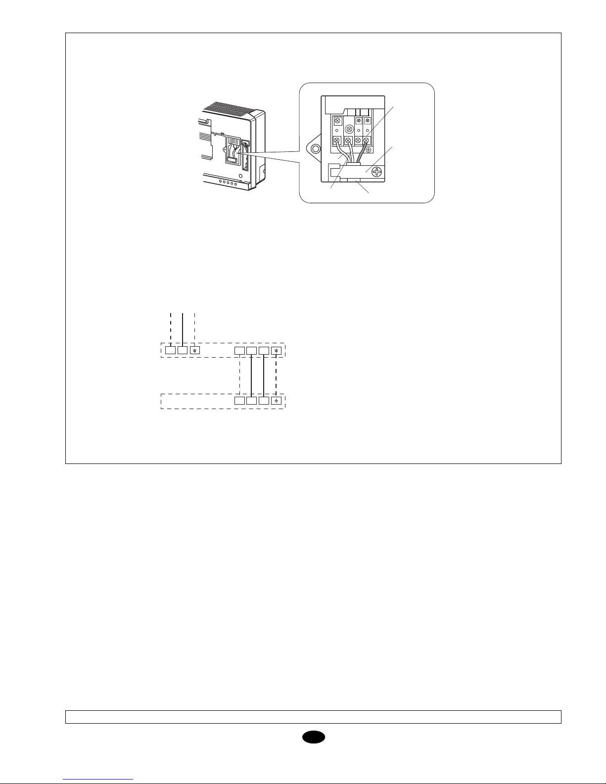
Wiring
1- Open the front panel.
2- Remove the wiring cover.
3- Locate the connecting cable from the
indoor unit, passing though the connect-
ing hole.
4- Connect the blue power supply cable to
terminal “N(1)”, the brown cable to “2”
and the yellow-green cable to the ground
connection, as indicated in Fig. 8.
5- For heat pump models, connect the
power supply cables as indicated in Fig.
8, and fasten the cable to the casing.
6- Install the electrical connection protec-
tor.
7- Mount the front panel.
Cable section
GB
Prior to final approval of the
installation
Check:
- The voltage is always between
198-254 V.
- The power supply cable section
is, at least, that recommended.
- Condensed water drainage is
carried out correctly, and there
are no leaks in the water circuit.
- Operating instructions have
been given to the user.
- Information has been given on
the need to clean the air filter
periodically.
- The guarantee card has been
filled out.
- Maintenance instructions have
been given, or a contract has
been made for periodical serv-
icing.
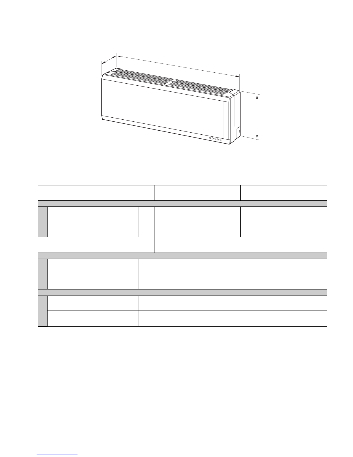
Sizes
Power supply
Interconnection
(ind./out.)
Fuse (K Curve)
Your product is marked with this symbol. This means that at the end of its service life it should not be mixed
with other non-classified household waste. Therefore, disposal should be carried out in compliance with the
corresponding local and national regulations, in a correct and environment-friendly manner.
The dismantling of the air conditioning unit, as well as the processing of refrigerant, oil and other compo-
nents, should be carried out by a qualified technician and in compliance with the applicable legislation.
Contact your local authorities for further information
ATTENTION
mm2
A
3 x 2,5
3 x 2,5
YVKC09DS YVKC12DS
10
4 x 2,5
4 x 2,5


BAR(S)XA-X(Y) User manual")


