manuals.online logo
Brands
  1. Home
  2. •
  3. Brands
  4. •
  5. Yotobike
  6. •
  7. Bicycle
  8. •
  9. Yotobike Leopard-Fat User manual

Yotobike Leopard-Fat User manual

Leopard-Fat Tires Electric
Mountain Bike
Owner's Manual
Content
This manual contains details of the product, information on its operation and maintenance, and other helpful tips for owners. Read it carefully
and familiarize yourself with the Yotobike
Yotobike
before using it to ensure safe use, reduce risk of damage and premature wear, and prevent accidents.
Be sure to retain this manual as your convenient information source.
This manual contains many Warnings and Cautions concerning safe operation, and consequences if proper setup, operation and main tenance
guidelines are not followed. All information in this manual should be carefully reviewed.
The safety grade color of Caution is orange, and if
not avoided, may result in moderate or serious injury.
The safety grade color of Warning is red, and if not
avoided will likely result in serious injury or death.
Users should also pay special attention to info-rma
tion marked in this manual beginning with “NOTICE”
Because it is impossible to anticipate every situation or condition which can occur while riding, this manual makes no represen tations about the safe use of our bicycles
under all conditions. There are risks associated with the use of any bicycle which cannot be predicted or avoided, and which are the sole responsibility of the rider.
You should keep this manual, along with any other documents that were included with your bicycle, for future reference, however all *The recommended minimum rider
age is 16 and over, and the maximum rider age is 70 and under. Any rider who cannot sit comforta adjustment of your Yotobike requires special tools and skills, and
it is recommended that this be performed by a trained bicycle mechanic if possible.
content in this manual is subject to change or withdrawal without notice. Visit Yotobike. com to download the latest version. A ssembly and first
not attempt to ride it.
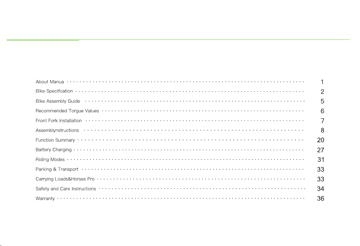
1
About Manual
2
Rear Derailleur
Rear Brake
Saddle Battery
Controller
LED Headlight
Front Brake
Motor
Head Tube
Rear Shock
Front Suspension Fork /
Front Shock
Bike Specification
A - Total Length 82.6 Inch
B - Handlebar Height 46.5 Inch
C - Wheelbase 55.1 Inch
D - Min Seat Height 32 Inch
E - Max Seat Height 37 Inch
F - Chain Stay Length 20.8 Inch
G - Standover Height 31.4 Inch
H - Top Tube Length 24 Inch
I - Wheel Diameter 28.7 Inch
J - Head Tube Length 6.3 Inch
K - Handlebar Length 27.6 Inch
I
I
I
3
US standard 3.0 A smart charger
60-80
48V 20Ah Battery with SamsungCells
miles 48V/25A
1000W brushless gear hub motor LCD display with USB charging
400 lbs 70 lbs
5'3" ~ 6'5" 0~5 level pedal assist
26" x 4.8" CST fat tires Thumb throttle
Aluminum alloy comfort grip levers with motor
cutoffswitch
Alloy front suspension fork with lockout and
adjustment
Battery powered bike light Alloy pedal with reflectors
Shimano 7 - speed gear shift system 6061 aluminum frame
180mm Hydraulic Brakes 48V LED light
KMC chain SR saddle
Promax MA-400 SSABK φ31.8mm*300mm Alloy Seatpost
170 mm forged alloy Heavy- duty aluminum
Shimano- 1 4 -2 8 T BROWN/ BK 13 gauge front / 12 gauge rear
Battery
Range
Motor
Total Payload
Capacity
Rider Heights
Tires
Brake lever
Taillight
Freewheel
Brake
Chain
Stem
Crankset
Gearing
Charger
Controller
Display
Weight
Pedal Assist
Intelligent
Throttle
Front Fork
Pedal
Bike Frame
Headlight
Saddle
Seatpost
Kickstand
Spokes
4
Headlight
Power cable
Transformer
Quick- release skewer
Pedals
Hex wrench
NOTICE: 1. Pleasekeep the original packaging for at least 15 days!
2 . Before assembling your bike, it’ s recommended to remove the battery for the reasons outlined below:
• Determine if there’ s battery drain or damage during shipping.
• Reduce the weight of the ebike to make it easier to maneuver the bike while assembling.
• Avoid battery damage during the assembly process.
Bike Assembly Guide
Preparation Checklist
◆
5
Hardware Location Recommended Torque(NM)
Handlebar 12-18
Stem 12 -18
Saddle 12-18
Front Wheel (for bikes with bolts on front wheel) 15-22
Rear wheel 30-38
Bottom Bracket Parts 30-50
Pedals 28-33
Disk Mounting Bolts 3-5
Disk Caliper Mount 6-8
Crank Bolts 32-36
Rear Derailleur Cable Pinch 3-5
Front Derailleur Clamp 3-6
Saddle Post Clamp 3 -6
NOTICE: Using an impact driver to achieve the required torque is not recommended as it might cause damage. We suggest you use the wrench set
we provided and extra tools to manually adjust nuts and bolts.
6
Recommended Torque Values
7
Front Fork Installation
◆Handlebar Installation ( 4mm Hex Wrench )
Step 1 : Loosen the bolts on your bike stem.
8
Step 2:
Step 3:
Center your handlebars and rotate them to align to the marking pointed to in the below image.
Tighten bolts to handlebar stem, but don’t tighten completely as you may want to further adjust the angle later to align more precisely. Test the
positioning, and adjust the handlebar to your preferred angle. After determining the best position, completely tighten all the bolts on the stem.
NOTICE: In addition to angle,
the height of the handlebar
can be adjusted by adding or
removing the headset spacers
if needed. For those without
experience, we recommend
having a professional make
such adjustments for safety
reasons.
Assembly Instructions
◆Front wheel
Step 1 : Take out the black guard block of the front fork. Pull out the red pad, which is used to protect the hydraulic brake caliper.
Step 2: Roll the wheel in between the front fork. Align the fork dropouts with the axle of the wheel hub, making sure the dropouts are fully
seated on the axle. Also, ensure the brake rotor is properly inserted into the caliper.
Step 3: Prepare your quick-release skewer for the next step by removing the thumb nut and one of the cone springs.
9
Step 4 : Install quick-release strings from the side without brake discs, inserting the quick-release skewer through the hub, and then replacing the
second cone spring on the other side. Ensure both springs are pointed narrow-side-in towards the wheel hub.
Step 5 : Tighten the thumb nut until the quick-release lever is held in line with the axle, and then use your palm of your hand to close the quick-release lever.
WARNING: Do not pull the brake lever without having either the red pad or the brake disc inserted, as this will damage the hydraulic brake caliper.
10
Step 6 : Inflate the tires and make sure they have sufficient pressure forriding comfort and safety, not exceeding the limit specified on the sidewall.
Step 7 : Rotate the front wheel. Make sure to fully close the quick release skewer lever on the front wheel and check the wheel balance in Pedal Only Mode. If
notice the riding is imbalanced or the rotation of the front wheel makes noise, it means the bolts were not completely tightened or not aligned you
horizontally.
11
12
◆Headlight (4mm Hex Wrench & 10mm Wrench)
Step 1 : Loosen the bolts on the fork brace. While holding the nut with a 1 0 mm wrench, unscrew the bolt with a 4 mm hex wrench.
Step 2 : Align the bolt holes of both your front light and the front fender together with the hole on the fork brace, then reinsert thebolt through all holes
and tighten the bolt with a 1 0 mm wrench and a hex wrench. Make sure the washer is directly under the bolt head.
◆Pedals Installation (15mm Wrench)
Make sure your pedals are installed on the correct side, as installing on the wrong side will damage the threads. Indicators for the right pedal ( R) and the left can
be found in two places: the stickers on the plastic cover, and the bottom of the pedal threads.
Before you install the pedals, apply a small amount of waterproof grease onto the spindle. Start threading the pedal on by hand to ensure the pedal is going in
perfectly straight, rotating in the direction of the pointer shown on the crank. If it is not spinning smoothly, make doubly sure that you have each pedal on the correct
side. After initial hand-tightening, finish tightening the pedals with a standard 15 mm wrench .
13
14
◆Seat Adjustment
Adjust the Seat Height:
Open the seatpost quick release lever.position. Do not extend the seatpost beyond the minimum insertion marking etched onto the seatpost
Adjust the seatpost height by sliding the seatpost up or down to a height appropriate foryour leg length and prefered riding
WARNING: Overextending the seatpost can cause it to break or come off your bike, putting you at very high risk of serious injury or
death. Avoid this danger by inserting your seatpost into the seat tube far enough that the minimum insertion point is no longer visible.
Adjust the Seat Angle:
Loosen the seat adjustment bolt beneath the seat. Move the seat backward or forward and tilt to adjust the angle within the limit markings etched on the seat
rail. Do not exceed the limit markings, to ensure the safety of yourself and the bike.
Tighten the seat adjustment bolt. Ensure the top and bottom of the seat rail clamp are aligned, so that the seat adjustment bolt will clamp the seat rails
together properly.
Step 1:
Step 2:
NOTICE: The seat angle has been preadjusted to factory safety standards. Please make note of original settings, and only adjust if necessary.
15
16
Please write down the serial numbers found on the head tube, battery and motor on the inside front cover of this manual to facilitate failure reporting. Make
sure each letter and number is correct.
Bike frame number Battery serial number
◆ After Bike Assembly
Motor serial number
17
Basic Steps
o Test front and rear brakes for proper function.
o Ensure brake pads are not overworn and are correctly positioned in relation to rims.
o Make sure brake control cables are lubricated, correctly adjusted and display no obvious wear.
o Check that brake control levers are lubricated and tightly secured to handlebars.
o Inflate tires to within recommended limits displayed on sidewalls.
o Check for bulges or signs of excessive wear.
o Clean tires to ensure tread is exposed.
o Ensure rims run true and have no obvious wobbles or kinks.
o Check that all wheel spokes are tight and not broken.
o Check the wheel balance in Pedal Only Mode. If you notice the riding is imbalanced or the rotation of the front wheel makes noise, it means
the bolts were not completely tightened or not aligned horizontally.
o Check that chain is oiled, clean and runs smoothly.
o Use extra care in wet or dusty conditions.
o Securely tighten pedals to cranks.
o Ensure cranks are securely tightened and are not bent.
o Check that derailleur( s) are adjusted and functioning properyl.
o Ensure shift and brake levers are attached to handlebar securely.
o Check all brake and shift cables for proper lubrication.
o Ensure hub motor is spinning smoothly and motor bearings are in good working order.
o Check that all power cables running to hub motor are secured and undamaged.
o Make sure hub motor axle bolts are secured and all torque arms and torque washers are in place.
o Ensure battery is charged before use.
o Check for any visible damage to battery pack.
o Lock battery securely to frame.
s
als
Safety Check
Brakes
Wheels and Tire
Chain
Cranks and Ped
Derailleurs
Motor Drive
Battery Pack
Safety Checklist
18
The following safety notes provide additional information on the safe operation of your Yotobike bike and should be closely reviewed. Improper operation, or failure
to confirm correct installation, compatibility, and maintenance of any component or accessory may result in serious injury or death.
◆Before Riding
•
•
•
•
•
r
I
All users must read and understand this manual before first use. Additional manuals for components used on your bicycle may beprovided and should also be
ead before use.
Ensure you understand all instructions and safety notes/warnings.
Follow the safety checklist before first use and at regular use to ensure the bike is properly fastened and set up.
Ensure the bike fits you properly before first use. Check local rules and regulations before riding.
t is your responsibility to familiarize yourself with the laws and requirements of operation of this product in the area( s) where you ride.
◆While Riding
•
•
•
•
•
Always wear an approved bicycle helmet whenever using this product and ensure that all helmet manufacturer instructions are us ed for fit and care of your
helmet. Failure to wear a helmet when riding may result in serious injury or death.
Acceleration can be unexpectedly strong in pedal assist mode (Pedal Assist level 1-5), as when you pedal the motor assist willsuddenly engage. Therefore, please
pay careful attention when riding. We suggest you use Pedal Only Mode (Pedal Assist level 0) when you need to ride at a slow speed to cross roads, at intersections
or when pedestrian traffic is present, in order to avoid accidents caused by sudden acceleration. .
Make sure you securely close the quick-release lever of the front wheel, checking the wheel balance in Pedal Only Mode. If you notice the riding feels imbalanced,
or the rotation of the front wheel makes noise, it likely means the bolts were not completely tightened or didn’t align horizontally in the center.
Off-road riding requires close attention and specific skills, and presents variable conditions and hazards which accompany the conditions.
Wear appropriate safety gear and do not ride alone in remote areas.
Safety Precautions

Popular Bicycle manuals by other brands

Orbea ALMA HYDRO 2021 Technical manual

Orbea

Orbea ALMA HYDRO 2021 Technical manual

Look 977 manual

Look

Look 977 manual

SNAPCYCLE R1 user manual

SNAPCYCLE

SNAPCYCLE R1 user manual

Moustache TRAIL 3 quick start

Moustache

Moustache TRAIL 3 quick start

RIEJU Bye Bike One 2015 owner's manual

RIEJU

RIEJU Bye Bike One 2015 owner's manual

Beone CRD29 competition user guide

Beone

Beone CRD29 competition user guide

Shulz Krabi manual

Shulz

Shulz Krabi manual

Scott 2008 Bike owner's manual

Scott

Scott 2008 Bike owner's manual

YT Industries TUES 27 Carbon Assembly instructions

YT Industries

YT Industries TUES 27 Carbon Assembly instructions

Estarli e20 quick start guide

Estarli

Estarli e20 quick start guide

HEINKEL Perle owner's manual

HEINKEL

HEINKEL Perle owner's manual

Pepita LittleONE LD-W-0144 user guide

Pepita

Pepita LittleONE LD-W-0144 user guide

Lekker Jordaan+ Assembly & maintenance guide

Lekker

Lekker Jordaan+ Assembly & maintenance guide

Peloton PL-31 user manual

Peloton

Peloton PL-31 user manual

smartmotion eUrbans Assembly instructions

smartmotion

smartmotion eUrbans Assembly instructions

Firefly Electric Handcycle user manual

Firefly

Firefly Electric Handcycle user manual

Merkava MunroE user manual

Merkava

Merkava MunroE user manual

RooDog Tourer user manual

RooDog

RooDog Tourer user manual

manuals.online logo
manuals.online logoBrands
  • About & Mission
  • Contact us
  • Privacy Policy
  • Terms and Conditions

Copyright 2025 Manuals.Online. All Rights Reserved.