12 BoSS X-Series Instructions for Use
3 - Safety rules3 - Safety rules
These safety rules should be adhered to in
every way.
NEVER exceed the 240kg rated capacity
(Safe Working Load or SWL) of the
platform
NEVER use the BoSS X-Series machine as a
crane
NEVER attempt to increase the reach or
working height of the BoSS X-Series
machine by use of additional
equipment eg ladders
NEVER use the BoSS X-Series machine in
temperatures exceading 50oC or
below -20oC
NEVER manoeuvre the BoSS X-Series
machine on an inclined surface
otherwise it may become
uncontrollable
NEVER release the brakes or manoeuvre the
BoSS X-Series machine whilst in an
elevated position as this may cause
instability
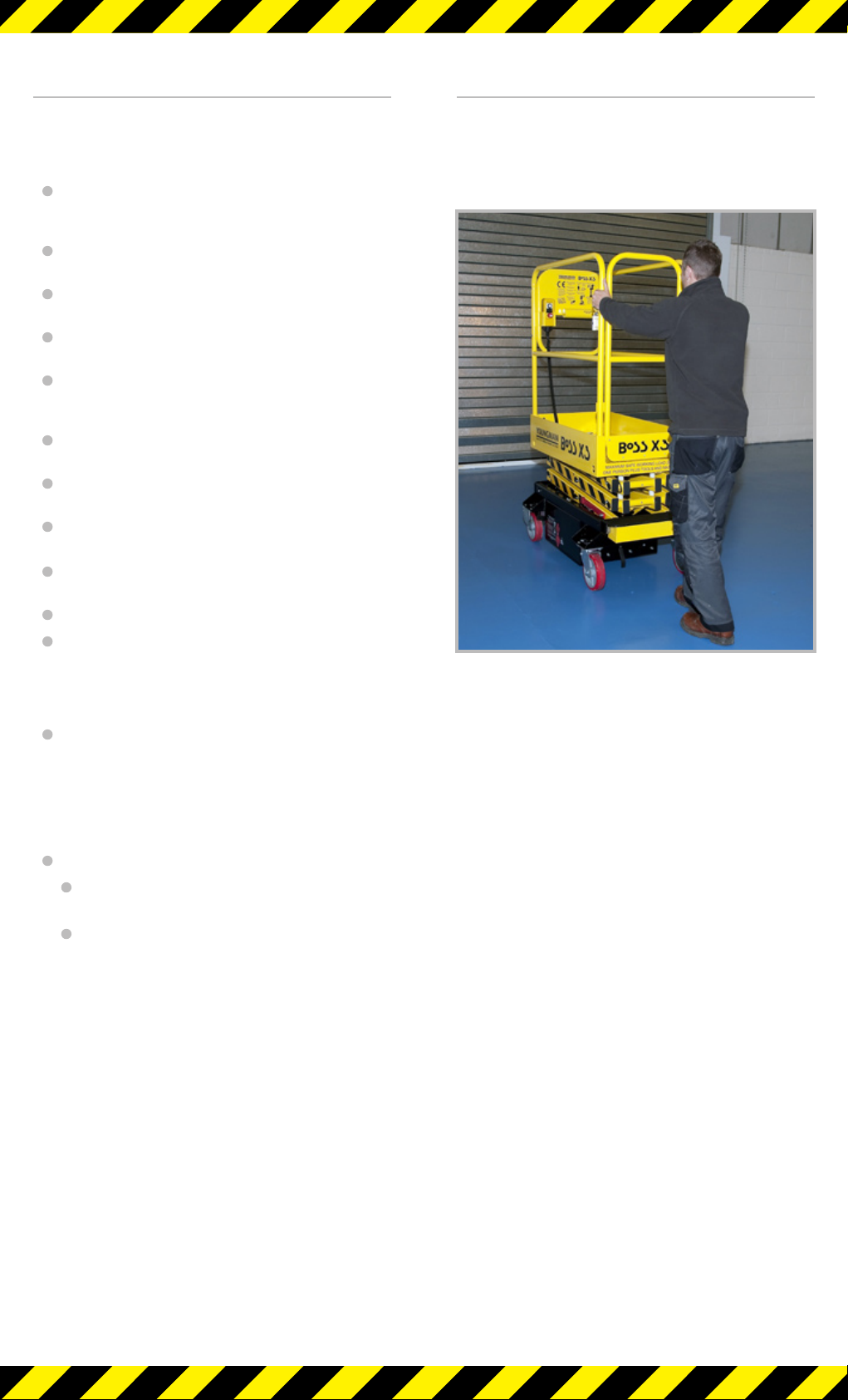
NEVER manoeuvre the BoSS X-Series
machine with a person or materials
on the platform.
NEVER attempt to get on or off the work
platform of the BoSS X-Series
machine when elevated
NEVER apply external side loads to the
platform or scissor structure
NEVER allow persons at ground level to
operate the controls whilst the
platform is occupied (unless in an
emergency situation)
NEVER operate the BoSS X-Series machine
outdoors
NEVER use the BoSS X-Series machine as
a jack, prop or tie to support other
structures or machines etc.
NEVER interfere with, wedge or attempt
to override hydraulic, electrical or
mechanical safety devices
NEVER remove the platform guardrails when
the machine is in use
NEVER allow works overhead of the BoSS
X-Series machine to be carried out
which are outside the control of the
operator
NEVER use the BoSS X-Series machine as
an electrical earth when welding
structures alongside it
NEVER use the guardrails to carry materials
NEVER attempt to overreach
ALWAYS check that there are no
obstructions or persons that
may be struck by the platform
before and during the raising and
lowering of the platform
ALWAYS carry tools and materials within
the confines of the guardrails of
the work platform
ALWAYS undertake the daily checks
recommended in this handbook
prior to the operation of the machine
ALWAYS ensure that all instructions, warning
and safe working load labelling
and plates are clean and legible
ALWAYS ensure the BoSS X-Series machine
is positioned on adequate ground
to support the weight of the
machine and its rated load.
ALWAYS keep the BoSS X-Series machine
clear of live electric conductors
ALWAYS keep the BoSS X-Series machine
away from contact with fixed
objects (buildings etc) or moving
objects (vehicles, cranes etc)
ALWAYS ensure hands are within the
confines of the guardrails when
elevating the work platform
ALWAYS ensure the access gate is closed
and latched once the operator has
entered the work platform
ALWAYS ensure that another responsible
person on site knows how to use
the emergency controls
ALWAYS ensure the weight is evenly
distributed within the platform
ALWAYS ensure the safety of persons that
may enter the area around the
platform and keep other vehicles
clear of the work area (eg cordon off
areas to prevent persons and other
vehicles entering the danger area)
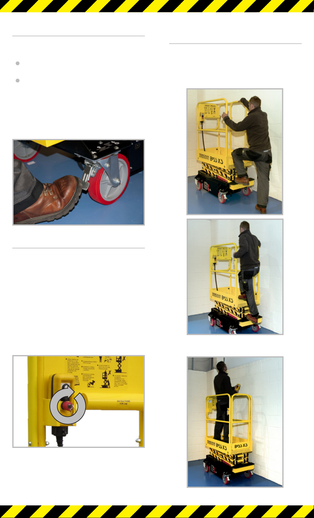
ALWAYS lock the swivel castors when
machine is stationary whether or
not it is in use
ALWAYS ensure the tilt sensor alarm
sounds when the power is
switched on
ALWAYS ensure the battery is charged
before use
ALWAYS read and understand these
Instructions for Use before using
the machine
ALWAYS use fail-safe props if working
under the work platform
ALWAYS thread the hoisting straps inside
the guardrails when hoisting the
machine
ALWAYS check that the LOLER certification
of the machine is in date before
use (UK ONLY)