YSI ProDSS User manual

USER MANUAL
ProDSS
USER MANUAL
DOCUMENT #626973-01REF

i
This page left intentionally blank

I
Contents
Introduction 3
Safety information 3
Precautionary symbols 3
Product components 3
Battery use and battery life 4
Charging the battery pack 5
Battery replacement 6
Connect the handheld to the cable assembly 8
ProDSS sensor installation/removal 9
Operation 13
Keypad and navigation 13
Startup 14
Navigation 14
Main display description 15
System menu 16
Sensor menu 22
Calibration menu 28
Files menu 29
Taking measurements 32
Calibration 33
Before calibration 33
Calibration setup (pH, ORP, ISE, conductivity, turbidity) 33
Conductivity 35
Barometer 36
Dissolved oxygen 37
pH/ORP 39
Depth 41
Turbidity 42
ISEs: Ammonium, Nitrate, & Chloride 44
Maintenance and storage 51

II
ProDSS handheld instrument 52
Cable, bulkhead, and connectors 53
Sensor guard 53
Depth sensor maintenance and storage 54
Turbidity sensor 55
Conductivity/temperature sensor 56
Dissolved oxygen sensor 57
pH - pH/ORP sensors 61
ISE sensors 63
KorDSS software installation 67
Install the KorDSS software 68
ProDSS driver installation 69
KorDSS startup wizard 72
Accessories 73
Ordering 73
ProDSS handhelds 74
ProDSS cable assemblies (No sensors included) 74
ODO/OBOD sensor and cable assemblies - DO/Temp only 75
ProDSS smart sensors 75
Replacement sensor modules and ODO sensor caps 75
ProDSS accessories 76
Calibration standards 77
Safety and support 79
Rechargeable Lithium-Ion battery pack safety warnings and precautions 79
Service information 81
Technical support 81
Declaration of Conformity 82
Warranty 84
Appendix A - DO% calibration values 85
Appendix B - oxygen solubility table 87

3
Introduction
Thank you for purchasing the YSI Professional Digital Sampling System (ProDSS).
ProDSS features include:
• Digital smart probes that are automatically recognized by the instrument when connected
• Waterproof (IP-67) case
• Long-life rechargeable lithium-ion battery pack
• Color display and backlit keypad
• User-selectable cable options
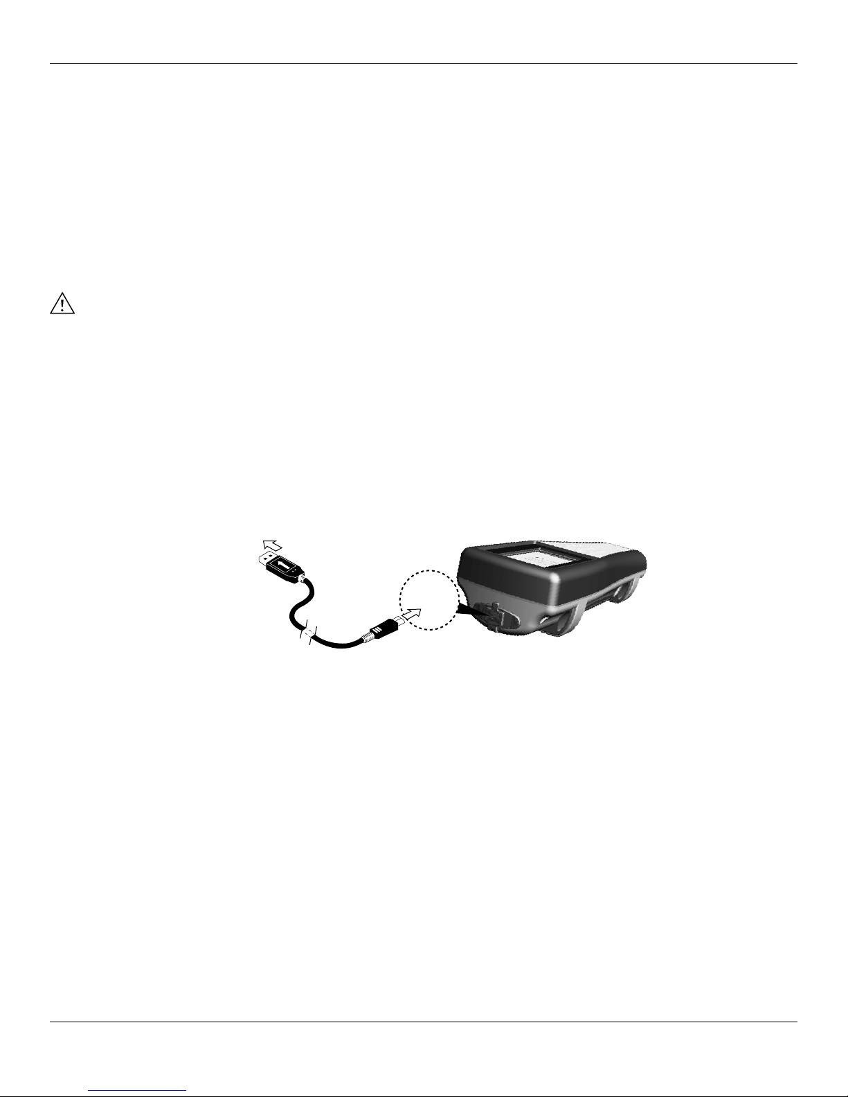
• USB connectivity
• Global Positioning System (GPS) (optional)
• Depth sensor (optional)
• Large memory with extensive site list capabilities
• Rugged enclosure with rubber over-molded case and miltary-spec (MS) connectors
Safety information
Please read this entire manual before unpacking, setting up or operating this equipment. Pay attention to all
precautionary statements. Failure to do so could result in serious injury to the operator or damage to the equipment.
Make sure that the protection provided by this equipment is not impaired. Do not use or install this equipment in any
manner other than that specified in this manual.
NOTICE: The manufacturer is not responsible for any damages due to misapplication or misuse of this product
including, without limitation, direct, incidental and consequential damages, and disclaims such
damages to the full extent permitted under applicable law. The user is solely responsible to identify
critical application risks and install appropriate mechanisms to protect processes during a possible
equipment malfunction.
Precautionary symbols
NOTE: Information that requires special emphasis
NOTICE: Indicates a situation which, if not avoided, may cause damage to the instrument
CAUTION: Indicates a potentially hazardous situation that may result in minor or moderate injury
WARNING: Indicates a potentially or imminently hazardous situation which, if not avoided, could result in death
or serious injury
Product components
Carefully unpack the instrument and accessories and inspect for damage. If any parts or materials are damaged,
contact YSI Customer Service at 800-897-4151 (+1 937 767-7241) or the authorized YSI distributor from whom the
instrument was purchased.
A

4
Introduction
Battery use and battery life
The ProDSS uses a rechargeable lithium-ion (Li-Ion) battery pack as a power source. The battery comes pre-installed in
the ProDSS and does not need to be replaced until the battery charge capacity is deemed unacceptable by the user.
The battery is shipped at ~50% full capacity and charging the battery is not required before first use.
Battery life depends on use, enabled parameters, LCD brightness, and GPS use. As with all lithium-ion batteries, battery
life will decline over time and use. This decay is typical and should be expected.
A new ProDSS battery is expected to last for the following durations (25 °C (77 °F), auto sampling, GPS on, keypad
backlight off):
• ProDSS instrument only - 48 hours
• ProDSS with fully loaded cable assembly and 25% (Default) LCD brightness - 20 hours
• ProDSS with fully loaded cable assembly and 100% LCD brightness - 14 hours
To increase battery life, enable manual sampling mode (Sampling on page 20). Manual sampling mode powers the
sensor/s on to take a measurement and then powers down to conserve battery life. Battery life may also depend on
the battery charging practices used. For maximum battery life, keep the battery 40% to 80% charged. Also, a larger
discharge (e.g. to 50%) is better than a small discharge (e.g. to 90%) between recharges.

5
Introduction
Charging the battery pack
A USB cable is included with the ProDSS to charge the instrument battery pack and connect the instrument to a PC.
The instrument battery pack can be charged from the AC power adapter, directly from a computer USB connection or
from an external, portable USB battery pack (sold separately, see ProDSS accessories on page 76).
Plug the USB connector into the AC power adapter, computer USB connector or external USB battery pack, then plug
the micro USB connector into the ProDSS instrument (Figure 1).
NOTE: The ProDSS internal charge controller only allows the battery pack to be charged if the temperature is
between 0 and 45 °C (32 and 113 °F).
WARNING: Charge the battery pack in an open area away from flammable materials, liquids, and surfaces. Read
Rechargeable Lithium-Ion battery pack safety warnings and precautions on page 79.
The ProDSS will charge faster when plugged into an AC outlet for charging rather than a PC’s USB port. For the
instrument to recognize that it is using AC power, you must start charging the ProDSS while on. After the instrument
recognizes it is being charged, it can be turned off to finish charging.
When using the AC adapter, it takes approximately 14 hours to charge the ProDSS battery when the instrument is
turned off during the charge. The amount of time required to completely charge the battery pack when the ProDSS is
initially turned on during the charge is approximately 9 hours.
Figure 1 Connecting the ProDSS to AC power supply
A

6
Introduction
Battery replacement
NOTE: The battery pack is pre-installed in the ProDSS instrument.
WARNING: Do not charge or handle a battery pack that is hot to the touch. Failure to follow the safety warnings
and precautions can result in personal injury and/or instrument damage not covered under
warranty. Read Rechargeable Lithium-Ion battery pack safety warnings and precautions on page
79.
1. Remove the battery pack cover by unscrewing (counter-clockwise) the four screws with a flat or Phillips head
screwdriver (Figure 2 on page 7).
NOTE: The retaining screws are captured into the battery pack cover and are not removable.
2. If replacing an existing battery pack, remove the Li-Ion battery pack and battery pack gasket/cradle. With two
fingers, grasp the battery pack connector and pull the connector straight up to disconnect and remove.
NOTE: Properly dispose of the old battery pack (Battery Disposal on page 80).
NOTE: A new gasket/cradle is included with a new battery pack to prevent water leaking into the instrument case.
When replacing the battery pack, use the new battery pack gasket/cradle supplied with the replacement
battery pack.
3. Inspect the replacement battery pack and battery pack gasket/cradle for damage. Contact YSI customer service
if the new battery pack and/or replacement gasket/cradle is damaged.
4. Correctly align and seat the battery pack gasket/cradle and battery pack into the instrument.
5. Align the battery pack connector wire terminals with the three instrument pins, then connect the battery pack to
the instrument.
NOTICE: Make sure that the three wire terminal connectors and three instrument pins are correctly aligned
before connecting the battery pack connector. Incorrect installation can damage the battery pack
connectors or instrument pins.
6. Install the battery pack cover, then tighten the cover screws. Make sure that the cover sealing surface is correctly
aligned and free of any contamination or damage.
NOTICE: Overtightening the cover screws can damage the battery cover.
A

7
Introduction
Figure 2 Battery replacement
1Battery pack cover 4 Instrument pin connectors
2Battery pack 5Battery pack gasket/cradle*
3Battery pack connector 6Battery pack gasket/cradle installed
*Color shown for reference
2
3
5
6
4
1

8
Introduction
Connect the handheld to the cable assembly
The ProDSS cable connectors are keyed for positive mating and to prevent connector damage (Figure 3). The ProDSS
instrument retains its IP-67 rating when the cable is disconnected. However, the connectors are not wet-mateable and
should be clean and dry before connecting.
Align the keys on the cable assembly connector with the slots on the instrument connector. Push together firmly, then
twist the outer ring clockwise until it locks into place.
Figure 3 Keyed connectors
1 Handheld female
connector
3 Keyed area of
connectors
2 Cable male connector
112223
1
2
3

9
Introduction
ProDSS sensor installation/removal
NOTICE: The ProDSS bulkhead and sensor connectors are not wet-mateable. Make sure that the sensor and
bulkhead connectors are clean and dry before sensor installation.
Figure 4 Sensor installation
1 Sensor 4 Sensor retaining nut
2 Port plug 5 Sensor installation/removal tool
3 Bulkhead
Sensor installation
The ports on the ProDSS bulkhead are universal; therefore, you can install any sensor into any port. For highest
accuracy, always install a conductivity/temperature sensor to compensate all measurement data for temperature and
dissolved oxygen data for conductivity.
1. Remove and discard the dust plugs shipped with the instrument (Figure 5 on page 10).
2. Inspect the bulkhead port for contamination. If the port is wet, clean it with compressed air.
3. Apply a thin coat of Krytox o-ring lubricant to the sensor o-rings. Wipe off any excess o-ring grease with a lint-
free cloth.
4. Carefully align the sensor and bulkhead connectors by inserting the sensor into the port then gently rotating the
sensor until the connectors align. Once aligned, push the sensor toward the bulkhead until the sensor seats in
the port.
5. Carefully finger-tighten the retaining nut clockwise.
NOTICE: If any resistance is felt, loosen the retaining nut completely to prevent cross-threading. Incorrect
installation may cause damage to the sensor or bulkhead that is not covered by the warranty.
6. Use the sensor installation/removal tool to tighten the retaining nut clockwise until snug, about a 1/4 to 1/2
additional turn of the retaining nut.
NOTICE: Do not over-tighten the retaining nut. Over-tightening can cause damage to the sensor or bulkhead
not covered by the warranty.
1
2
3
4
5

10
Introduction
Sensor removal
To remove a sensor, insert the sensor installation/removal tool into the retaining nut, then rotate the retaining nut
counterclockwise to loosen. After the retaining nut has been completely unscrewed from the bulkhead, pull the sensor
straight out of the port and place it on a clean surface.
NOTICE: Install a port plug if not reinstalling a sensor in the exposed port. Exposure to water can cause
damage or corrosion to the bulkhead connectors not covered by the warranty.
Port plugs
Figure 5 Port plugs
1 Shipping dust cover* 2 Port plug
*Color shown for reference
To protect the bulkhead connectors from damage, install a port plug into any port without an installed sensor. Port
plugs and a tube of o-ring lubricant are included in the maintenance kit that ships with all ProDSS cables. Refer to the
accessories section if an additional maintenance kit is needed (Ordering on page 73).
NOTICE: The shipping dust covers installed on the bulkhead when purchased (not sensor installation/removal
tool compatible) are not o-ring sealed and must be replaced with a port plug before field use.
NOTICE: Do not submerge the bulkhead without a sensor or port plug installed in all ports.
Installation
1. Apply a thin coat of Krytox o-ring lubricant to the o-rings on the plug port.
2. Remove any excess lubricant from the o-rings and port plug with a lint-free cloth.
3. Insert the port plug into the empty port and press until firmly seated.
4. Finger-tighten the port plug clockwise to install. If necessary, use the sensor installation tool to make sure that
the plug is fully seated into the port.
NOTICE: The o-rings will not be visible if a port plug is correctly installed.
NOTICE: Do not over-tighten the port plug. Over-tightening can cause damage to the port plug or bulkhead
not covered by the warranty.
1
2

11
Introduction
Sensor guard and weight installation
1. Carefully slide the sensor guard over the bulkhead and attached sensors/port plugs. Push the sensor guard
toward the bulkhead until the sensor guard threads align with the bulkhead threads.
2. Carefully finger-tighten the sensor guard clockwise.
NOTICE: If any resistance is felt, loosen the sensor guard completely to prevent cross-threading. Incorrect
installation may cause damage to the sensor guard or bulkhead that is not covered by the warranty.
NOTICE: Do not submerge the bulkhead without a sensor or port plug installed in all ports.
Figure 6 Sensor guard and weight installation
1 Sensor guard 4 Depth sensor (if equipped)
2 Bulkhead 5 Weight
3 Bulkhead threads
1
2
3
4
5

12
Introduction
Sensor guard weights
To help stabilize the sensors when profiling at deeper depths, a sensor guard weight is supplied with cables 10 meters
and longer. To attach the weight, carefully hand-tighten it clockwise on to the bottom of the sensor guard (Figure 6 on
page 11).
NOTICE: If any resistance is felt, loosen the sensor guard weight completely to prevent cross-threading.
Incorrect installation may cause damage to the sensor guard.
The bottom of the weight is threaded so that additional weights can be added if needed. See ProDSS accessories on
page 76.
NOTE: Do not have any weights installed on the sensor guard when calibrating using the calibration cup.

13
Operation
Keypad and navigation
Figure 7 Keypad description
1 System: Opens the system menu. Use to adjust
system settings
7 ON/OFF: Turn on or turn off the instrument
2 Exit/Escape key: Exits to the Run screen. When in
an alpha/numeric entry screen, returns to previous
menu
8 Right arrow key: Navigate right in an alpha/
numeric entry screen. On the Run screen, push to
show graphical representations of the displayed
measurements. Push the right or left arrow to return
to the Run screen. In the View Data screen, push to
view additional parameters in the data set
3 Left arrow key: Navigate left in an alpha/numeric
entry screen. Push to return to previous menu in all
screens except alpha/numeric entry. On the Run
screen, push to show graphical representations of
the displayed measurements. Push the right or left
arrow to return to the Run screen
9 Backlight: Turns the keypad backlight on or off for
use in low light conditions
4 Help: Shows context sensitive help 10 File: Opens the file menu. Use to view logged data
and GLP files, backup data to a USB stick, and delete
data
5 Up/down arrow keys: Scroll through menus or
enter numbers and letters
11 Calibrate: Opens the calibration menu. Use to
calibrate all parameters except temperature
6 Enter key: Push to confirm selections. On the Run
screen, push to log a single data point or start
continuous data logging
12 Probe: Opens the sensor menu. Use to setup
sensors, change the measurements shown on the
run screen, and turn on/off Auto Stable and GPS
3
2
1
4
5 6
7
9
8
10
10
1112
5
?
Esc
Cal
ENTER
System Probe Calibration File

14
Operation
Startup
Push the key to turn on the handheld. If the handheld does not turn on, make sure that the battery pack is correctly
installed and charged. Push and hold the key for 1.5 seconds to turn the handheld off.
Navigation
The ProDSS contains menus to change user-defined options, functions, and parameters. Use the arrow keys
(and ) to highlight different options within menus and sub-menus, then push the ENTER key to select the option.
Push the key to return to the previous menu.
NOTE: When in an alpha/numeric screen, the key is for alpha/numeric navigation only. Push the
Esc
key to
return to the previous menu.
Push the
Esc
key to return to the Run screen. To enable or disable an option, highlight the option, then push the ENTER
key. Enabled functions appear as a circle with a dot or a box with a check mark . Disabled functions appear as a
circle only or an empty box .
Alpha/numeric entry
When required, an alpha or alpha/numeric entry screen will be shown. When finished entering information, highlight
ENTER, then push the ENTER key to save the entry (Figure 8).
NOTE: When in an alpha/numeric screen, the key is for alpha/numeric navigation only. Push the
Esc
key to
return to the previous menu.
Figure 8 Alpha/numeric and numeric entry screens
1 User entry field 4 Enter selection
2 Delete entire entry 5 Upper/lowercase
3 Backspace
1
2
3
4
5
2
3
1
4
1
2
3
4
5
2
3
1
4

15
Operation
Main display description
The main display (Run screen) shows the current measurements as defined in the Sensor Display menu
(Sensor Display on page 25). If more measurements are selected than can be displayed on the Run screen, a scroll
bar will be shown. Use the and arrow keys to view the additional measurements (Figure 9).
The message area shows status messages, error messages, and information about selected functions.
Figure 9 Main display example
1 Log or sampling (update measurements) prompt on
Run screen (single or continuous)
6 Battery charge %
2 Current screen/menu 7 USB/PC connection indicator
3 Date/Time 8 Scroll bar
4 GPS signal indicator 9 Message area
5 Battery charging indicator 10 Displayed measurements
2
3
1
4
5
6
7
9
10
8

16
Operation
System menu
Push the System key to view and adjust instrument settings. Highlight a sub-menu then push the ENTER key to view
the sub-menu options (Figure 10).
Pre-defined or user-selected options are noted within brackets ([]). See Alpha/numeric entry on page 14.
Figure 10 System menu
Use the System menu to:
• Set the date and time (Date/Time on page 17)
• Change the user-defined Good Laboratory Practices (GLP) options
(GLP menu on page 17)
• Change the instrument language setting (Language on page 19)
• Change the radix point (Radix Point on page 19)
• Change logging options (Logging on page 19)
• Change sampling options (Sampling on page 20)
• Set the handheld auto-shutoff time (Auto-Shutoff on page 20)
• Set the backlight mode (Backlight on page 21)
• View the software version (Alpha/numeric entry on page 14)
• View the handheld serial number (Serial # on page 21)
• View and adjust the Unit ID (Unit ID on page 21)
• View the sensor specific information (Sensor info on page 22)
• Adjust the display brightness (Brightness on page 22)

17
Operation
Figure 11 Date/Time
Date/Time
→Date/Time
For accurate logging and GLP data, correctly set the date and time
options (Figure 11). Select any of the following options to set the Date/
Time in the ProDSS.
Date/Time options:
• Set YY/MM/DD, MM/DD/YY, DD/MM/YY or YY/DD/MM date format
• Set the correct date
• Select 12 or 24 hour time format
• Set the correct time
GLP menu
Detailed sensor calibration information is stored in the Good Laboratory Practice (GLP) file for later review.
One GLP file is used to store all calibration records. The instrument’s internal memory can save up to 400 individual
calibration records. After 400 records, the instrument will overwrite previously stored calibration records, starting with
the oldest.
To prevent the permanent loss of GLP records, periodically download the GLP file to a computer using the KorDSS
software.
NOTE: GLP files uploaded to the PC will overwrite a previously downloaded GLP file if it has the same file name.
To prevent data loss, move or rename previously downloaded GLP files before downloading the GLP file.
Figure 12 GLP record example (single
point % DO calibration)
GLP saved information
See Figure 12.
• Sensor calibrated
• Date/time stamp
• Sensor ID
• Sensor software version
• Calibration method (Conductivity and ODO calibrations)
• Calibration value
• Temperature
• User ID (optional)
• Probe ID (optional)
• User fields #1 and #2 (optional)
• Calibration status

18
Operation
Figure 13 GLP Options
GLP Options
→GLP → Options
User ID, Probe ID, or User Field #1 or 2 can be user-defined for positive
GLP file identification of:
• The person calibrating the instrument.
• The sensor/cable serial number used during calibration (or other,
user-defined Probe ID).
• Other user-specific identification (User Field #1 and #2) (Figure 13).
NOTE: User Field can be used to describe the condition of the
probe. For example, new sensor or new ODO cap.
Figure 14 Re-Cal Prompts
Re-Cal Prompts
→GLP →Options →Re-Cal Prompts
Re-Cal Prompts provide a reminder to recalibrate a probe in the
user-defined number of days (Figure 14).
The Re-Cal prompt will be displayed in the message area of the main
display when the set time has elapsed (Figure 9 on page 15).
Select the desired sensor Re-Cal prompt, then enter the desired number
of days before the Re-Cal prompt occurs.
Set the sensor value to zero (0) days (default) to turn off Re-Cal prompts.
NOTE: When enabled and the set amount of time since the last
calibration has passed, the Re-Cal prompt will be shown
when the instrument is turned on.
Figure 15 GLP Security
GLP Security
→GLP → Security
The Calibration menu can be password protected to prevent accidental
or unauthorized sensor calibration (Figure 15).
1. From the GLP menu, select Security, then enter the default
password “ysi123”.
2. Select Set Password [] and change the default password.
3. Select the Protect Cal check box to password protect the
Calibration menu.
NOTE: Write down and keep the password in a safe place. Contact
YSI Technical Support if you lose the password (Technical
support on page 81).
Other manuals for ProDSS
6
Table of contents
Other YSI Laboratory Equipment manuals