YSI YSI-ProDSS User manual

YSI ProDSS supplement 1 July 2015
MULTIMETER: YSI-ProDSS
EQUIPMENT NEEDED
•YSI-ProDSS multimeter
•data sheet, clipboard, pencil
Note:
The ambient temperature range
over whi h the battery pa k an be
dis harged is -20°C to 60°C (-4°F to
140°F). Use of the battery pa k outside of
this temperature range may damage the
performan e of the battery pa k or may
redu e its life expe tan y.
INITIAL INSTRUMENT PREPARATION:
1.
CABLE CONNECTION
Inspect the cable connection between the
handheld meter and the cable
If cable is not connected to the meter,
make
sure the onne tors are lean and dry
before onne ting!
If connecters are clean
and dry, align the keys on the cable assembly
connector with the slots on the instrument
connector Push together firmly, and then twist
the outer ring clockwise until it locks into place
The metal pin should “snap” into place and be
visible through small hole in the outer ring (see
image below)
Image of outer ring with metal pin locked in
place
2.
SENSOR GUARD AND
SENSOR(S) CHECK
If any of the individual sensors are not
connected, Refer to “Settings and
Troubleshooting” section for sensor installation
If there is an empty “slot” with no sensor
installed,
a port plug or sensor must be
installed or the bulkhead will be
damaged!
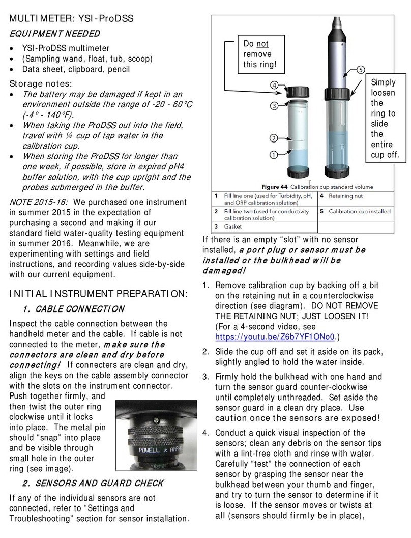
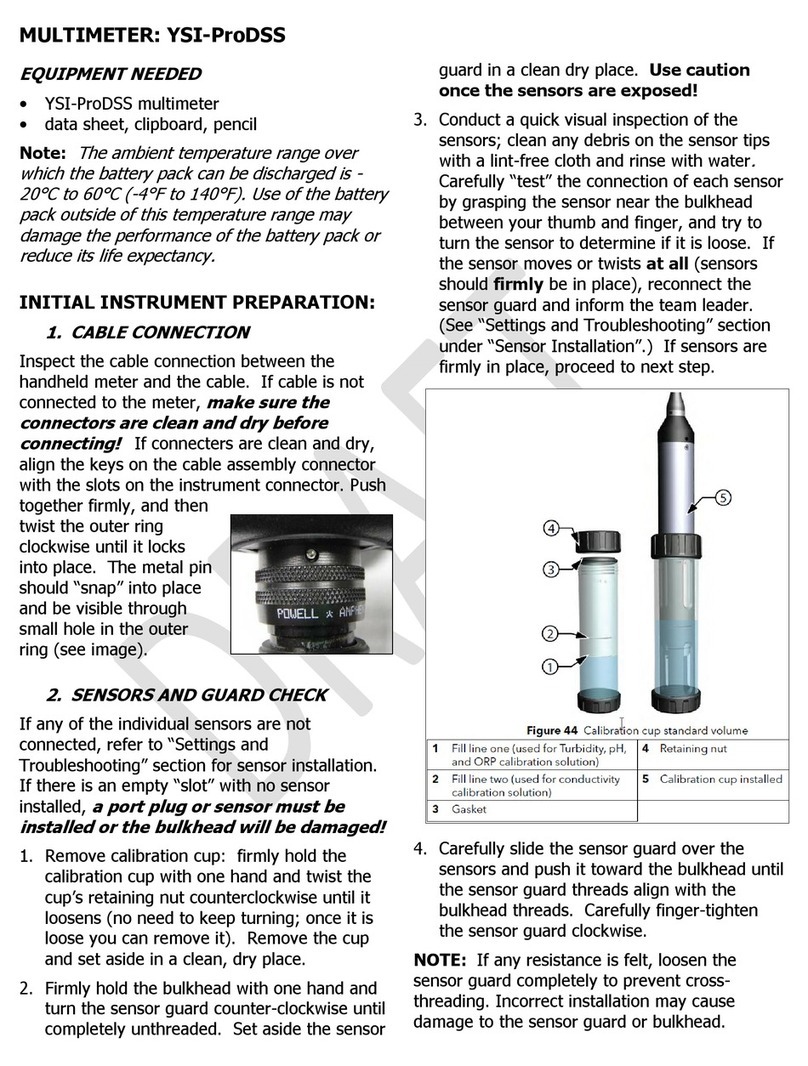
Remove calibration cup and inspect the sensor
guard and sensors
1 Firmly hold calibration cup with one hand
and twist the cups retaining nut
counterclockwise until it loosens (you do not
need to keep turning, once it is lose you can
remove it) Set the cup aside in a clean and
dry place
2 Firmly hold the bulkhead with one hand and
turn the sensor guard clockwise until
completely unthreaded Set aside the
sensor guard in a clean dry place Use
aution on e the sensors are exposed!
3 Conduct a quick visual inspection of the
sensors; look for any debris on the sensor
tips, if there is carefully clean with a lint-free
cloth and rinse with water
Carefully “test”
the connection of each sensor by grasping
the upper portion of the sensor between

YSI ProDSS supplement 2 July 2015
your thumb and pointer finger, and try to
turn the sensor to determine if it is loose If
the sensor moves or twists at all (sensors
should firmly be in place), reconnect the
sensor guard and inform the team leader If
any sensor is loose refer to the “Settings
and Troubleshooting” section under “Sensor
Installation” If sensors are firmly in place,
proceed to next step
4 Carefully slide the sensor guard over the
bulkhead and attached sensors/port plugs
Push the sensor guard toward the bulkhead
until the sensor guard threads align with the
bulkhead threads Carefully finger-tighten
the sensor guard clockwise
NOTICE:
If any resistance is felt, loosen the
sensor guard completely to prevent cross-
threading Incorrect installation may cause
damage to the sensor guard or bulkhead that is
not covered by the warranty
INITIAL INSTRUMENT PREPARATION:
Where to sample: Pick an area where the
stream is flowing and appears to be well mixed
Do not sample downstream of where your
team has disturbed the bottom.
1 Turn on the meter by pushing the
power
key
to turn on the handheld To turn off
the meter, hold down the power key for 1 5
seconds If the handheld does not turn on,
inform the team leader The handheld could
have a dead battery, or the battery pack
may need to be inspected Removing and
examining the battery pack needs to be
done with extreme care by a team leader in
a dry, clean place, preferably not in the
field! For instruction on battery pack
removal, refer to the “Settings and Trouble
Shooting” section under “Battery
Troubleshooting” Once you have reviewed
the battery troubleshooting procedures, and
are in a dry, clean environment, make sure
that the battery pack is correctly installed
and charged
Charging the Internal Li-Ion Battery Pa k
Use YSI designated charging equipment only!
If the battery is not charged, the meter must be
charged from the AC power adapter
(strongest
charge source)
, directly from a computer USB
connection or from an external, portable USB
battery pack For the instrument to recognize
that it is using AC power, you must start
charging the ProDSS while on After the
instrument recognizes it is being charged, it can
be turned off to finish charging When using
the AC adapter, it takes approximately 14 hours
to charge the ProDSS battery when the
instrument is turned off during the charge The
amount of time required to completely charge
the battery pack when the ProDSS is initially
turned on during the charge is approximately 9
hours Expected battery life:
• ProDSS instrument only - 48 hours
• ProDSS with fully loaded cable assembly and
25% (Default) LCD brightness - 20 hours
• ProDSS with fully loaded cable assembly and
100% LCD brightness - 14 hours
For maximum battery life, keep the battery
40% to 80% charged Also, a larger
discharge (e g to 50%) is better than a small
discharge (e g to 90%) between recharges
2 The main display, or “run Screen” will
appear, take note of the battery life at the
top right, which is displayed as a
percentage If the battery life is low, inform
your team leader
3 Study the main “run” screen Confirm the
following:
•The date and time are correct:
The date and time should be displayed at
the top of the screen; if not, refer to the
“Settings and Troubleshooting” section
under “Date/Time”
•Logging is correct:
At the top of the screen in the green bar
it should read “log one sample”; if not,
refer to the “Settings and
Troubleshooting” section under “Logging
Data”

Pro-DSS
YSI ProDSS supplement 3 July 2015
•Individual parameter units are correct:
Units:
temperature - °C
barometer – inHg
dissolved oxygen – DO%
dissolved oxygen – DO mg/L
conductivity – SPC-µS/cm
salinity – SAL-ppt
turbidity – NTU
If any parameters are not displayed on the
Run Screen, or if any of the above units do
not match the units displayed on the Run
Screen, refer to the “Settings and
Troubleshooting” section under “Sensor
Display Details”
4 Select Site and Data ID:
(Data ID will determine the sample type, i e
primary sample or replicate)
a) Select the
System Button
, and then
select
logging
b) Before selecting a site and data ID, make
sure the
Use Site List
and
Use Data ID
List
check boxes have been selected
c) Select
Site [site name]
, scroll down until
you find the desirable site and hit enter
d) Select
Data ID [sample type]
, scroll
down until you find the desirable sample
type and hit enter (i e
Primary Sample
)
e) Hit escape to return to the Run Menu
NOTE: You will want to change the site
settings and the sample type (if
appropriate) at each site you visit
5 Place the probe in the stream Set the
meter in a safe place on the bank for ____
minutes to let the meter warm up and the
probe stabilize to stream temperature
6 Re ord the barometri pressure, to the
nearest 0 01 in Hg (inches of mercury), plus
time and sampler’s initials If it does not
say “inHg” next to the reading, refer to the
“Settings and Troubleshooting” section
under “Sensor Display Details”
TAKING MEASUREMENTS FOR DISSOLVED
OXYGEN, TEMPERATURE, CONDUCTIVITY,
SALINITY, AND PH.
1
Insert the probe in the stream:
Standing downstream or to the side of the
probe, place it in the current facing the
probe downstream, in a place with steady
flow, adequate depth, good mixing, and no
surface turbulence Leave the probe at this
location in the stream for approximately 10
minutes
2
Stabilize:
After the probe has acclimated to the
stream conditions, turn on the Auto Stable
feature:
a) Hit the
probe button
, then select Auto
Stable
b) Confirm the following:
- Parameters are set to [on] (pH is in
ISE)
-
Continuous Mode
and
Log Samples
boxes are checked
-
Sample Period(s)
is set to [12]
-
Sample Count
is set to [10]
Auto Stable s reen should mat h
the image below
c) Scroll to the bottom of the screen and
select Start Auto Stable.

YSI ProDSS supplement 4 July 2015
On the Run Screen there will be a flashing
red symbol next to each parameter that
was selected for Auto Stable Wait until
these flashing red symbols become green
, at this point the sensors have
stabilized
7
Re ord the readings:
Once all the parameters have stabilized
press enter to log a reading Record the
following readings, in the following order,
using our rounding convention as necessary
(see Quality Assurance protocol):
a)
Temperature
: to nearest 0 1°C
b)
DO % Saturation
: to nearest 0 1%
c)
DO Con entration:
to nearest 0 1
mg/L
d)
Condu tivity:
Record to the nearest
whole number of µS (microSiemens)
e) Salinity: “ppt” to the nearest tenth
This is the salinity in parts per thousand
f) pH: to the nearest 0 1
g) Turbidity: FNU
8
If you’re taking repli ates at this site:
Remove probe from stream, shake off
water, and replace in stream
Before you
take a se ond reading, do the
following:
From the Run Screen select the
System Button
, scroll down and select
Logging. In the Logging menu, select Data
ID and select Replicate. Exit back to the
Run Screen and collect a second reading
(same as above) Also take a
repli ate
barometer reading
and record it with the
replicate data
10
Shake off the probe, rinse with purified
water if the stream water is dirty, fill
the alibration up with 2” of water,
and repla e the probe in the
alibration up.
Put the unit in the shade
if possible
11 If you are not submitting the data to Clallam
County, record the latest calibration dates
for DO (“Winkler”), conductivity, and
temperature Select the
File button
,
select View GLP and scroll through to see
when the instrument was last calibrated
11 If you have replicates to transcribe, select
the
File button
, then select Show Data
If no data is displayed make sure you have
the right date and time entered at the
bottom After selecting Show Data scroll
down until you find the proper site and data
ID (the data ID will usually say either
Primary Sample or Replicate) Continue as
above to record readings Next, check the
“Water Chemistry—General” protocol to see
if your pairs of readings are within the
acceptable precision limits, and resample as
needed
12 Record the sampler’s initials for both sample
and replicate
Sampler’s Initials
Be sure to put all the initials of one sampler
taking responsibility for the data; this should be
someone who has been properly trained (see
“Quality Assurance” protocol)
13
Perform a DO drift he k:
Hit Esc to
return to the “Run” Screen to view the DO%
saturation If haven’t already, fill the
calibration cup with ~2” of clean water
Loosely tighten the cup onto the bulkhead,
do not completely tighten, you want it loose
for atmospheric venting Keep the meter
and probe in the shade, if possible, and
allow the probe to stabilize as before:
STABILIZATION CRITERION: During a
period of 2 minutes, both DO Sat % and
temp (°C) stay within 0.1 of their initial
readings.
Do NOT hit any buttons on the meter
When stabilization is reached, you’ll
want the DO % Saturation reading to be
between 98-102%; if not, you’ll need to re-
calibrate the meter and re-take the

Pro-DSS
YSI ProDSS supplement 5 July 2015
readings, or your data will be flagged as
“estimated” or “rejected”
14 If the stabilized DO % Saturation reading is
satisfactory, record it to the nearest 0 1%
15 Record the time and sampler’s initials
16
Turn off the meter
, fully tighten the
calibration cup and place the unit in the field
bag
COMMON SENSE AND EXPECTED RANGES:
Please compare your readings with the
expected ranges on the datasheet If you’re outside
the expected range, consider re-sampling or
troubleshooting with your fellow samplers
Conductivity readings in particular have a
nasty habit of being wacky Stream conductivity is
rarely lower than 25 µS If your readings are lower
than this, you’ll need to troubleshoot:
-- If the reading is 0 0 or 0 1, you might be reading
the salinity (“ppt”) screen rather than the proper
conductivity screen; if so, scroll through the screens
again (by pressing ENTER) until you get to the right
one
-- You might not have held the probe completely
underwater Try taking another set of readings
-- The readings might be in mS rather than µS (see
above)
MEASURED VS. CORRECTED READINGS:
The data for DO saturation and concentration will
get adjusted once entered into the database,
according to the pressure, temperature, and salinity
you recorded This formula avoids a built-in error in
the YSI-85, which assumes “normal” atmospheric
pressure for a given altitude, when actually that
pressure can vary from normal by 5% or more

YSI ProDSS supplement 6 July 2015
MULTIMETER: YSI ProDSS
Settings and Troubleshooting
Table of Contents:
1 Sensor, Port Plug, Guard Installation
•Sensor installation
•Port Plug Installation
•Sensor Guard Installation
2 Battery Pack Troubleshooting
3 System Settings
•Date/Time
•Logging Data
•Sensor Display Details
1. SENSOR, PORT PLUG, GUARD
INSTALLATION
Perform sensor/port plug installation in a clean,
dry environment, do not install in the field!
The ports on the ProDSS bulkhead are
universal; therefore, you can install any sensor
into any port For highest accuracy, always
install a conductivity/temperature sensor to
compensate all measurement data for
temperature and dissolved oxygen data for
conductivity
Before installing a sensor or port plug,
make sure that the sensor and
bulkhead
onne tors are lean and dry before
sensor/port plug installation!
If there is an
empty “slot” with no sensor or port plug
installed,
a port plug or sensor must be
installed or the bulkhead will be
damaged!
Equipment needed for sensor/port plug
installation:
•Sensor(s) and or port plug(s)
•Bulkhead
•Krytox o-ring lubricant
•Sensor installation/removal tool
•Lint-free cloth
Sensor Installation
1 Inspect the bulkhead port for contamination
If the port is wet, carefully dry with a lint-
free cloth
2 Apply a thin coat of Krytox o-ring lubricant
to the sensor o-rings Wipe off any excess
o-ring grease with a lint-free cloth
3 Carefully align the sensor and bulkhead
connectors by inserting the sensor into the
port then gently rotating the sensor until the
connectors align Once aligned, push the
sensor toward the bulkhead until the sensor
seats in the port
4 Carefully finger-tighten the retaining nut
clockwise NOTICE: If any resistance is
felt, loosen the retaining nut completely to
prevent cross-threading Incorrect
installation may cause damage to the sensor
or bulkhead that is not covered by the
warranty
5 Use the sensor installation/removal tool to
tighten the retaining nut clockwise until
snug, about a ¼ to ½ additional turn of the
retaining nut NOTICE: Do not over-
tighten the retaining nut Over-tightening
can cause damage to the sensor or
bulkhead not covered by the warranty
If there is an empty slot in the bulkhead, install
a port plug
Never submerge the bulkhead
without a sensor or port plug installed in
all ports!

YSI ProDSS supplement 7 July 2015
Port Plug Installation
1 Apply a thin coat of Krytox o-ring lubricant
to the o-rings on the plug port
2 Remove any excess lubricant from the o-
rings and port plug with a lint-free cloth
3 Insert the port plug into the empty port and
press until firmly seated
4 Finger-tighten the port plug clockwise to
install If necessary, use the sensor
installation tool to make sure that the plug is
fully seated into the port
NOTICE: The o-rings will not be visible if a
port plug is correctly installed Do not over-
tighten the port plug Over-tightening can
cause damage to the port plug or bulkhead
not covered by the warranty
5 Install the sensor guard If sensor guard is
not attached, sensors are extremely
venerable to environmental damage
Sensor Guard Installation
1 Carefully slide the sensor guard over the
bulkhead and attached sensors/port plugs
Push the sensor guard toward the bulkhead
until the sensor guard threads align with the
bulkhead threads
2 Carefully finger-tighten the sensor guard
clockwise
NOTICE:
If any resistance is felt, loosen the
sensor guard completely to prevent cross-
threading Incorrect installation may cause
damage to the sensor guard or bulkhead that is
not covered by the warranty
2. BATTERY PACK
TROUBLESHOOTING
Do not remove the battery pa k if it is hot
to the tou h, is produ ing an odd odor, or
is leaking a fluid. Removing and examining
the battery pack needs to be done with
extreme care by a team leader and in a dry,
clean place, preferably not in the field!
If the instrument is not turning on do the
following:
1 Attempt to charge the unit: Using YSI
charging equipment only, plug unit into
the AC adapter with the USB connector
If this does not power on the unit,
proceed to next step
2 Remove battery pack cover and examine
battery pack (figure below):
a) Remove the battery pack cover by
unscrewing (counter-clockwise) the
four screws with a flat or Phillips
head screwdriver (the retaining
screws are captured into the cover
and are not removable
b) Inspect the battery pack, make sure
the battery pack connector is
properly connected to the
instrument
c) If the connectors do not appear to
be properly connected, with two
fingers, grasp the battery pack
connector and pull the connector
straight up to disconnect and
remove Inspect the connector and
instrument pin connectors for any
debris or damage If the connectors
look ok, align the battery pack
connector wire terminals with the
three instrument pins and connect
the battery pack
Do not remove the battery pa k if it
is hot to the tou h, is produ ing an
odd odor, or is leaking a fluid
d) If connectors look properly
connected, reinstall the battery
cover and attempt to charge the unit
again If the unit still will not turn
on, the battery pack may need to be
replaced Before ordering a new
battery pack, call YSI at
800 765 4974 and troubleshoot
problems with a ProDSS tech
e) If a new battery pack has been
ordered, refer to the YSI manual for
battery removal/disposal, and
replacement

YSI ProDSS supplement 8 July 2015
Refer to the figure on the next page for
a reference
3. SYSTEM SETTINGS
Date/Time
If the date and time are inaccurate, press the
system button
, go to the Date/Time
submenu option, scroll down to Date and hit
enter In the numeric entry screen use the arrow
keys to maneuver around If entire date needs
corrected click the
delete entire entry
key
, if
not use the
backspace key
to partially correct
the date After correcting the date, hit enter
Scroll down to Time and hit enter, follow similar
instructions for date correction to correct the time
When finished hit the Esc or left arrow button
until you are back to the Run screen
Logging Data
If the logging settings are inaccurate, press the
system button
, scroll down to the logging
submenu option, go to the Continuous Mode
and uncheck the box by pressing enter The box
should become unchecked Press the Esc
button to return the Run Screen In the green bar
at the top of the screen it should now read “Log
One Sample”
Sensor Display Details
If there is a parameter not displayed on the
Run Screen, inform the team leader If
parameter not present, either the sensor is not
installed correctly, or it is not working properly
To check if the sensor is installed properly, refer
to the above section Sensor, Port Plug,
Guard Installation and carefully examine the
sensors
If the units do not match on the Run Screen, go
to the
probe button
and scroll down to
Display submenu and hit enter Scroll down
and select the desired parameter A submenu
will appear with multiple parameter unit
options, select the proper unit and return to the
Run Screen
Other YSI Multimeter manuals