Ytec3D HP45 User manual

2017
Ytec3D.com
Written by:
Yvo de Haas
Latest version:
07-01-2017
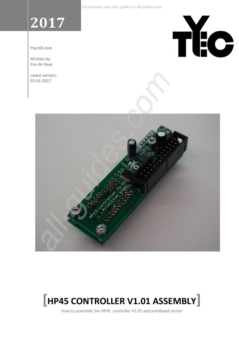
[HP45 CONTROLLER V1.01 ASSEMBLY]
How to assemble the HP45 controller V1.01 and printhead carrier

HP45 controller V1.01 assembly guide -Ytec3d.com- Page 2
Table of Contents
Introduction ............................................................................................................................................3
PCB assembly ..........................................................................................................................................4
Before you start ..................................................................................................................................4
Tools required..................................................................................................................................... 4
Bill of materials ...................................................................................................................................5
Assembly ...........................................................................................................................................11
Appendix 1: Schematics ........................................................................................................................17

HP45 controller V1.01 assembly guide -Ytec3d.com- Page 3
Introduction
In this assembly guide I try to show how to assemble the HP45 controller V1.01 and its carrier. While
this is not the simplest kit to assemble with a few hours and some experience in SMD soldering it
should be possible to assemble. How to operate the HP45 controller after assembly is described in a
different manual.
If there are questions left at the end of this document, you can visit the contact form on Ytec3D.com

HP45 controller V1.01 assembly guide -Ytec3d.com- Page 4
PCB assembly
Before you start
This controller has parts that are quite difficult to solder by hand and is not intended for beginners. It
is not really for anyone that has little to no experience with soldering SMD components. If you are
not completely sure about your soldering skills, this controller might be too difficult.
Tools required
To assemble the HP45 controller you will need the following tools:
Soldering iron with a fine SMD tip;
Fine (<0.5mm) resin core solder;
flush cutters;
Metal saw;
Files;
(optional, Dremel with a narrow cutting wheel);
(optional, 3D printer with 0.25mm nozzle for the pogo pin template);

HP45 controller V1.01 assembly guide -Ytec3d.com- Page 5
Bill of materials
Name:
HP45 controller V1.01 PCB
Quantity:
1
Part number:
-
Package:
-
Supplier:
Ytec3D.com
Link:
-
Note:
Name:
Pogo pin 0.68mm 16mm long
Quantity
52
Part number:
-
Package:
-
Supplier:
Ebay
Link:
http://www.ebay.com/itm/100pcs-P50-J1-Dia-0-
68mm-Length-16mm-75g-Spring-Test-Probe-Pogo-
Pin-Receptacle-
/151785406493?hash=item23571d801d:g:iAkAAOS
wIgNXl3Mt
Note:
Round head, buy more in case there
are damaged pins.
Name:
TLC59213
Quantity:
2
Part number:
595-TLC59213AIPWR
Package:
TSSOP-20
Supplier:
Mouser
Link:
http://mouser.com/Search/ProductDetail.aspx?R=T
LC59213AIPWRvirtualkey59500000virtualkey595-
TLC59213AIPWR
Note:
Name:
LM311
Quantity:
1
Part number:
863-LM311DR2G
Package:
SOIC-8
Supplier:
Mouser
Link:
http://mouser.com/Search/ProductDetail.aspx?R=L
M311DR2Gvirtualkey58410000virtualkey863-
LM311DR2G
Note:

HP45 controller V1.01 assembly guide -Ytec3d.com- Page 6
Name:
SIRA12DP-T1-GE3
Quantity:
1
Part number:
78-SIRA12DP-T1-GE3
Package:
SOIC-8
Supplier:
Mouser
Link:
http://mouser.com/ProductDetail/Vishay-
Semiconductors/SIRA12DP-T1-
GE3/?qs=sGAEpiMZZMshyDBzk1%2fWi34%252bjiTX
84hXNsjfRHjG4Os%3d
Note:
Name:
HEF4017
Quantity:
3
Part number:
771-HEF4017BTD
Package:
SO-16
Supplier:
Mouser
Link:
http://mouser.com/ProductDetail/NXP-
Semiconductors/HEF4017BT652/?qs=sGAEpiMZZM
utXGli8Ay4kDE4J8KCiPsFLWWSlq0qOaw%3d
Note:
Name:
HCF4081
Quantity:
1
Part number:
511-4081BM-TR
Package:
SOP-14
Supplier:
Mouser
Link:
http://mouser.com/ProductDetail/STMicroelectroni
cs/HCF4081M013TR/?qs=%2fha2pyFaduiKwCFISZSF
JLLSk1wqERWB2u%2fKE7DcyVY%3d
Note:
Name:
DMG2302UK-7
Quantity:
2
Part number:
621-DMG2302UK-7
Package:
SOT-23-3
Supplier:
Mouser
Link:
http://mouser.com/ProductDetail/Diodes-
Incorporated/DMG2302UK-
7/?qs=sGAEpiMZZMshyDBzk1%2fWi8ItRWc04xxfkC
1RM9bfNAr2kg0rvMh6TA%3d%3d
Note:
Alternate part. Original part is
IRLML2502PbF

HP45 controller V1.01 assembly guide -Ytec3d.com- Page 7
Name:
220Ω resistor 0.1W
Quantity:
1
Part number:
667-ERJ-3EKF2200V
Package:
0603
Supplier:
Mouser
Link:
http://mouser.com/ProductDetail/Panasonic/ERJ-
3EKF2200V/?qs=sGAEpiMZZMu61qfTUdNhG6gKAQ
VNBKOojXbh5RPUu0w%3d
Note:
Name:
1.2kΩ resistor 0.1W
Quantity:
1
Part number:
667-ERJ-3EKF1201V
Package:
0603
Supplier:
Mouser
Link:
http://mouser.com/ProductDetail/Panasonic/ERJ-
3EKF1201V/?qs=sGAEpiMZZMu61qfTUdNhG6gKAQ
VNBKOoTC0hNDHH3WI%3d
Note:
Name:
2.2kΩ resistor 0.1W
Quantity:
6
Part number:
667-ERJ-PA3F2201V
Package:
0603
Supplier:
Mouser
Link:
http://mouser.com/ProductDetail/Panasonic/ERJ-
PA3F2201V/?qs=sGAEpiMZZMu61qfTUdNhGwyN07
7O4KhFX9zrWTTJPlPrTO3Y9GhC2Q%3d%3d
Note:
Name:
10kΩ resistor 0.1W
Quantity:
2
Part number:
667-ERJ-3EKF1002V
Package:
0603
Supplier:
Mouser
Link:
http://mouser.com/ProductDetail/Panasonic/ERJ-
3EKF1002V/?qs=sGAEpiMZZMtlubZbdhIBIHcx2Q2R
nT7KusLiC2u%2fTVc%3d
Note:

HP45 controller V1.01 assembly guide -Ytec3d.com- Page 8
Name:
100nF ceramic capacitor
Quantity:
1
Part number:
81-GRM40X104K50L
Package:
0805
Supplier:
Mouser
Link:
http://mouser.com/ProductDetail/Murata-
Electronics/GRM21BR71H104KA01L/?qs=sGAEpiMZ
ZMs0AnBnWHyRQKf3b7LydMIhPJtWqHYP2rg%3d
Note:
Name:
1µF 100V electrolytic capacitor
Quantity:
1
Part number:
598-105CKE100M
Package:
5x11mm
Supplier:
Mouser
Link:
http://mouser.com/ProductDetail/Illinois-
Capacitor-
CDE/105CKE100M/?qs=sGAEpiMZZMtZ1n0r9vR22fP
Wwtj8kO8aGTdhkAsuCM5vYvIsVJPtRg%3d%3d
Note:
Voltages as low as 16V permitted.
Name:
100µF 16V electrolytic capacitor
Quantity:
1
Part number:
667-ECA-1CM101I
Package:
5x11mm
Supplier:
Mouser
Link:
http://mouser.com/ProductDetail/Panasonic/ECA-
1CM101I/?qs=sGAEpiMZZMsh%252b1woXyUXj7W
OPB%2fJZkV%252b0wpmeZSiF8c%3d
Note:
Higher capacitance allowed as long as
it is 5mm diameter.
Name:
2.54mm pin header, 5 pins
Quantity:
1
Part number:
653-XG8V-0831
Package:
-
Supplier:
Mouser
Link:
http://mouser.com/ProductDetail/Omron-
Electronics/XG8V-
0831/?qs=sGAEpiMZZMs%252bGHln7q6pm%252bv
5BXf4QdrTUprKlfXrIZ0%3d
Note:
Can be split.

HP45 controller V1.01 assembly guide -Ytec3d.com- Page 9
Name:
26 pin boxed header
Quantity:
1
Part number:
517-30326-6002
Package:
-
Supplier:
Mouser
Link:
http://mouser.com/ProductDetail/3M-Electronic-
Solutions-Division/30326-
6002HB/?qs=sGAEpiMZZMs%252bGHln7q6pm67xk
eHW1IZNYlL8VAGOtj8%3d
Note:
Name:
Screw terminal, 2 position, 3.5mm
Quantity:
1
Part number:
651-1984617
Package:
-
Supplier:
Mouser
Link:
http://mouser.com/ProductDetail/Phoenix-
Contact/1984617/?qs=sGAEpiMZZMvZTcaMAxB2AE
SRb0B7PLuENBlLLdAoFxM%3d
Note:
Name:
standoff, 5mm for M3
Quantity:
3
Part number:
855-R30-6200514
Package:
-
Supplier:
Mouser
Link:
http://mouser.com/ProductDetail/Harwin/R30-
6200514/?qs=sGAEpiMZZMtrde5aJd3qw4L16p8RLi
BxP8oCQaKYWd4%3d
Note:
Can also be made by hand using brass
or aluminium tube. Max OD 5mm.
Name:
DIN912 cilinder screw M3x12mm
Quantity:
3
Part number:
Package:
Supplier:
Link:
Note:
Temporarily used to hold the
controller together

HP45 controller V1.01 assembly guide -Ytec3d.com- Page 10
Name:
DIN934 M3 nut
Quantity:
3
Part number:
Package:
Supplier:
Link:
Note:
Temporarily used to hold the
controller together
Name:
Pin template
Quantity:
1
Part number:
-
Package:
-
Supplier:
Ytec3d
Link:
-
Note:
Optional, 3d printed. Used for
mounting the pogo pins more
accurately

HP45 controller V1.01 assembly guide -Ytec3d.com- Page 11
Assembly
With the warnings out of the way, all parts gathered and the soldering iron heated, it is time to start
assembling the controller.
1: The first step is to separate the 2 halves of the PCB. There is no scoring in the PCB, but there is a
line where the PCB roughly needs to be cut. On this line the PCB can be cut with a knife, thin metal
saw or Dremel with narrow cutting disc. As long as no traces are damaged with the cutting, it does
not matter where you cut the board. When you have cut the boards, there are 2 sides. The primitive
side and the address side. When this guide mentions up or front, it means with the primtive and
address side text facing up. Down or back is the opposing side.
(Note: in future versions, the boards will come in 2 pre-cut sections. The first batch does not have
this)
2: Solder the TLC59213 (IC1) on the front of the primitive side, with the marking facing towards the
26 pin boxed header connector. Be aware that the TLC has fine spacing and is difficult to solder by
hand.
3: Solder the TLC59213 (IC2) on the back of the primitive side, with the marking facing the IC2 text.
Be aware that the TLC has fine spacing and is difficult to solder by hand.
4: Solder the SIRA12DP-T1-GE3 (IC3) mosfet on the front of the primitive side with the marking
facing the 26 pin boxed header. The pins on the SIRA are hard to reach with the solder, and require a
bit of heat before the solder sticks to it.
1
2
3
4

HP45 controller V1.01 assembly guide -Ytec3d.com- Page 12
5: Solder the LM311 (IC4) on the back of the primitive side with the marking away from the boxed
header.
6: Solder 3x 4017 (IC5, IC6, IC7) on the front of the address side with the markings as shown in the
image.
7: Solder the 4081 (IC8) on the front of the address side with the marking as shown in the image.
8: Solder the DMG2302UK-7 (Q1, Q2) or a similar mosfets on the front of the address side.
9: Solder the 100nF capacitor (C3) on the front of the address side.
10: Solder 2x 10k resistor (R2, R5) on the back side of the primitive side.
5
6
7
8
9
10

HP45 controller V1.01 assembly guide -Ytec3d.com- Page 13
11: Solder the 1.2k resistor (R3) on the back side of the primitive side.
12: Solder the 220 resistor (R11) on the front of the primitive side.
13: Solder the 2.2k resistor (R1) on the front of the primitive side).
14: Solder 5x 2.2k resistor (R6, R7, R8, R9, R10) on the front of the address side.
15: Solder the 5 pin header in the front of the address side. Cut wires on the bottom side of the
address side as close as possible to the board.
16: Solder the screw terminal on the front of the primitive side.
11
12
13
14
15
16

HP45 controller V1.01 assembly guide -Ytec3d.com- Page 14
17: Solder the 26 pin boxed header in the front of the primitive side.
18: Solder the 1µF (C2) capacitor with the cathode facing away from the terminal in the front of the
primitive side. Cut the wires as short as possible after soldering.
19: Solder the 100µF (C1) capacitor with the cathode facing away from the terminal in the front of
the primitive side. Cut the wires as short as possible after soldering. (220µF shown in image)
At this point it is important to check all connections on the address front side and the primitive back
side . Make sure there are no shorts or unconnected pins. Once the 2 boards are fully soldered
together, they are not going to come apart again without some serious work. With this check, the
TLC59213 on the bottom of the primitive side is the highest risk of having a mistake.
Once you are happy with all the connections, you can move to the next steps.
20: Use the spacers, 12mm screws and one nut to mount the assembly to the primitive side. The 5
pin header should go from the address side and through the bottom of the primitive side. hand tight
is tight enough for the nuts in this stage of the build.
The set of 2 screw on the pogo pin side of the board should have no nuts. The M3 nuts will obstruct
the template later.
17
18
19
20

HP45 controller V1.01 assembly guide -Ytec3d.com- Page 15
21: Place the template with the marking facing down.
22: Place the combined controller on top of the template with the primitive front side up and
roughly align the holes.
23: Place the pogo pins with the sprung part down through the 52 holes. It is advised to check if
every pin springs before mounting it. After all pins are placed all pins should roughly stick the same
length out of the primitive front side board (about 2-3mm).
24 : Solder the primitive front side of all the pogo pins. It is important that no solder leaks into the
small hole in the back of the pogo pin. If this happens, the solder will seize the spring and the pogo
pin will be unusable.
21
22
23
24

HP45 controller V1.01 assembly guide -Ytec3d.com- Page 16
25: Remove the template and repeat step 24 with the bottom of the address side, making sure no
solder leaks into the joint between the static part and the sprung part of the pogo pin.
26: Solder the primitive front side of the 5 pin header and cut the wire flush with the board.
This finishes the PCB assembly.
25
26

Appendix 1: Schematics
Other manuals for HP45
1
Table of contents
Other Ytec3D Controllers manuals
Popular Controllers manuals by other brands

Hitachi
Hitachi HCWA10NEGQ Operation manual

Savant
Savant SmartLighting SSL-P018 Quick reference guide

Hermes
Hermes RT 100 D operating instructions

Balmar
Balmar Max Charge MC-624 Installation and operation manual

Mi Casa Verde
Mi Casa Verde VERA3 installation manual

Manson Engineering Industrial
Manson Engineering Industrial PVC-7820 user manual