Yudian AI-5500 User manual

1
CONTENTS: Page
Overview 2
Specifications 4
Input Wiring and Notes 6
DisplayScreen 8
KeypadOperation 10
MenuSettings 15
Description of Menu Parameters 17
Calibration 19
Description of Prompt Information 22
Accessories 24
OptionalAccessories 24

2
Overview
AI-5500 Handheld Economical Digital Thermometer, features high precision, high
stability, low power consumption, multiple input types, multiple measurement results,
easy operation, etc. When suitable sensors are matched, it can be widely used for
handheld precise temperature measurement in production, scientific research and labs.
Its main characteristics are as follows:
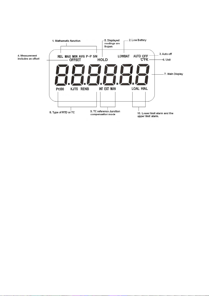
Input types:
Pt100, K, S, E, T, J, R, B, N. There are three compensation modes for thermocouples,
including internal compensation, external compensation and manual(simulated)
compensation.
Mathematical-statistical measurement:
Relative value, maximum value, minimum value, average value, peak-peak value,
standard deviation and sampling number can also be measured at the same time.
Resolution can be set:
0.1 oC/ 1 oC
Display units for thermal resistances and thermocouples:
Which can be switched at will, including oC, ℉and K.
Customized start-up display:
Including math modes, resolution, display units and the reference junction
compensation modes.

3
Other:
Clear LCD layout, white backlight,
Easy keypad operation and smart and exquisite appearance,
Upper limit alarm and lower limit alarm can be set,
Users calibration is provided,
Low power consumption; three AA alkaline batteries, 1,500 hours battery life(typical
value, backlight off).
Sensor offset correction, display holding.
Automatic backlight shut-off, automatic power shut-off and low battery voltage
detection.

4
Specifications
(1) Measurement Range and Accuracy
tyPE
Code
Type Effective Measurement
Range
1-year tolerance Δ
(see the notes)
1 Pt100 (-200.000~+850.000)℃±+0.5℃)
13 K (-200.00~+1372.00)℃±1.50℃
14 S (0.0~1768.0)℃±2.4℃
15 E (-200.00~+1000.00)℃±1.2℃
16 T (-200.00~+400.00)℃±1.2℃
17 J (-210.00~+1200.00)℃±1.2℃
18 R (0.0~1768.0)℃±2.4℃
19 B (300.0~+1820.0)℃±2.4℃
20 N (-200.00~+1300.00)℃±1.8℃
Notes:
1) Based on ITS-90 (ITS: The International Temperature Scale ); the
environmental condition: (23±5)℃, ≤85%RH; exclusive of sensor errors.
2) The thermal resistance and thermocouple’s measurement range and tolerance
shown in other units (℉and K) are equivalent to the above table.
3) The Fahrenheit degree (℉) is not the legal measurement unit in the P.R.C, so
Fahrenheit degree (℉) cannot be used as temperature measurement unit
except for special need.
4) When environmental condition not in (23±5) ℃, means (0~18) ℃and
(28~50) ℃, tolerance will increase 0.01Δ/℃

5
(2) Resolution: The highest resolution:
tyPE
Code tyPE Celsius
Degree ℃
Fahrenheit
degree ℉Kelvin K
1 Pt100
0 / 0.0 0 / 0.0 0 / 0.0
13 K
14 S
15 E
16 T
17 J
18 R
19 B
20 N
(3) Sampling Rate:
Input signals Sampling Rate
Thermocouple/ PT100
(MAN Compensation) 2.5 times/s
Thermocouple
(INT/EXT Compensation) 2 times/s
(4) Power Supply and Power Consumption:
Three 1.5V AA batteries. The operating current is not more than 1.5mA when the
backlight is shut off, when turned on, operating current about 27mA
(5) Conditions forApplication Environment:
Ambient temperature : (0~50)℃,
Ambient humidity : ≦85%RH
(6) Dimensions and Weight: 155 X 70 X 30 mm, about 0.25kg (Batteries included).

Input Wiring and Notes
6
e
rmocouple wire
u
ple meteria
l
Copper wire
Therm
o
Constant temperatur
e
Thermocouple
4-wire conne
c
Hihg- Pre c is ion
Digital-Thermometer
5600
UDIAN
Y
RT D/ Ω
TC/mV
mA
PTD or Resistor
Copper wi
4- wire conne c tor
Copper wir e
Hihg-Precis ion
Dig i ta l -Ther mome te r
5600
UDIAN
Y
RTD/ Ω
TC/mV
mA
RTD
Copper Wire
Thermocouple
Thermocouple
Wire
Copper
connector
4- Wire connector
F1:RTD F2:TC(INT) F3: TC (EXT)
1. Wiring for RTD type:
The 4-wire connection is adopted, which is shown as F1 in the above drawing.
Two wires which in red and white color are connected to one end of the RTD, and
two wires which in black and green color are connected to the other end of the
RTD.
Special Notes: the 4-wire connection plug cannot be used as USB interface
purpose. It cannot be plugged into any USB sockets of computers or other devices
so as to avoid damage
re
Copper c onec tor
m
ocouple wire
tu
re bath
Thermocouple
Pt100
n
ecto
r
Hihg-Prec is ion
Digi tal-The rmomete r
5600
UDIAN
Y
RTD/ Ω
TC/mV
mA
Copper Wire
4- Wire connector
Copper Wire
Copper connector
Thermocouple
Wire
Thermocouple
Constant Temp.
Bath

7
2. Wiring with the interior reference end compensation method (INT) is
adopted for thermocouples:
The same thermoelectric characteristics should be ensured for connection from the
thermocouple measurement end to the plug, that’s to say, the compensation wires
and plugs should be used as the same type as the “tyPE”, the extension type is
preferable. See F2 in the above drawing.
3. Wiring with the manual reference end compensation mode (MAN) or the
external reference end compensation mode (EXT):
The thermocouple to the constant temperature oven is connected by compensation
wires; The constant temperature oven to the instrument is connected by pure
copper wires and plugs. With regard to the external compensation mode (EXT),
a four-wire Pt100 platinum resistance is required to be inserted into the
constant temperature oven, and a four-wire plug is required to be connected to
the RTD socket of the instrument, which is shown as F3 in the above drawing.
Note 1:
If thermocouple plug and RTD plug are connected to sensor in the same
time, insulation between the sensors should be ensured, or the
measurement results will be affected.
Note 2:
If any signals exceeding 5V are input, the instrument will be damaged.

Display Screen
(1) REL/MAX/MIN/AVG/P-P/SN:
Mathematic function: Which respectively the relative value, maximum value,
minimum value, average value, peak-peak value, standard deviation and
sampling number. The standard deviation and sampling number have the
same sign “SN”.
(2) LOWBAT:
This sign is displayed when the battery voltage is low;
(3) AUTOOFF:
The sign is displayed when the automatic shutdown is set.
(4) OFFSET:
The sign is displayed when in the menu the sensor’s correction value
OFFSEt is not equal to 0.
(5) HOLD:
Display hold;
(6)℃/ ℉/ K:
Measurement units;
(7) 6-digital LCD display:
Measurement values or prompt information;
8

9
(8) Pt100 / K / J / T / S / R / E / N / B:
Type of RTD and thermocouples.
(9) INT/EXT/MAN:
Compensation modes for the thermocouple reference ends;
(10) LOAL/HIAL:
Indicates the lower limit or upper limit alarm.

Keypad Operation
Unit Math Resolt Hold
Power Light
∨/ ∧/
Set < /
Power Key Backlight
Key
Key 1 Key 2 Key 3 Key 4
Keys are divided into three types including the short keys, long keys and key
combinations. Long keys or key combinations (keys should be pressed and hold
for 2 seconds) are used to realize the functions of Set, Cancel, RJ or Cal, and
short keys are used to realize other functions.
(1) Power Key: Power switch, the automatic shut-off function can be realized
when the menu parameter AutoFF is not equal to 0. That’s to say, automatic
shut-off can be realized when no key-press time is larger than or equal to the time
set by AutoFF (unit: minute), and automatic shut-off is canceled when AutoFF is
equal to 0.
(2) Backlight Key: Backlight switch. The absolute value of the menu parameter
Auto.b.L is the backlight’s automatic shut-off time (second), and the backlight’s
automatic shut-off function is canceled in case of Auto.b.L=0. The positive and
negative signs of Auto.b.L indicate that if the buzzer sound for key-press and alarm
exceeding the lower/upper limit is allowed or not: buzzer sound is allowed when
10

11
Auto.b.L is no less than zero, and buzzer sound is not allowed when Auto.b.L is
less than zero.
(3) Key 1: in the measuring state, briefly press “Key 1” to switch display unit;
press “Key 1” and hold it for 2 seconds to realize the “Set” function and enter
menu settings. See Chapter 6 “Menu Settings” for details.
(4) Key 2:
1) In the measuring state, briefly press “Key 2” to select mathematic
measurement functions: The functions can be switched in the eight states of
“basic measurement values- REL-MAX-MIN-AVG- PP-s-n”. In which,
a) When no any “REL-MAX-MIN-AVG- PP-SN” signs appear, the value is
the current measurement value.
b) REL is relative measurement value. It is similar to “manual zeroing”,
subtracting the “reference value” from the current value, i.e. the REL value =
current measurement value xi–reference value. The “reference value” is the
measurement value in the beginning of star-up, or the measurement vale in
the beginning of altering input tyPE, or the measurement value in the
moment of pressing “Cancel”.
c) MAX is the maximum measurement value. It is the maximum
measurement value since start-up (or after pressing “Cancel”).
d) MIN is the minimum measurement value. It is the minimum measurement
value since start-up (or after pressing “Cancel”).
e) AVG is the average measurement value. It is the average value since

start-up (or after pressing “Cancel”):
AV G ∑
=
−==
n
ii
x
n
x
1
1
When the sampling number n exceeds 1 million times, the average value
calculation will be suspended and the displayed AVG value remain the same.
f) P-P is the peak to peak value during measurement. It is equal to the peak
to peak value for the measurement results since start-up (or after pressing
“Cancel”), i.e. P-P=MAX - MIN.
g) SN is the standard deviation and sampling number, and s and n
respectively refer to the standard deviation and sampling number below. The
first displayed value of SN is the standard deviation, which is equal to the
measurement value standard deviation since start-up (or after pressing
“Cancel”):
1
)(
1
2
−
−
=
∑
=
−
n
xx
s
n
ii
, in which n
x
x
n
ii
∑
=
−=1
When the sampling number n exceeds 1 million times, the deviation value
calculation will be suspended and the displayed value remain the same.
h) The second displayed value of SN is the sampling number, which is equal
to the sampling number since start-up (or after pressing “Cancel”):
n≤999,999. n is shown as “OVER” in case of n≥1,000,000, which is a
prompt that the average value and the standard deviation are the
12

13
measurement results up to 1,000,000 times.
Notes: When the sampling number exceeds 1 million times, the average value,
standard deviation and sampling number will be suspended and remain the same,
and the measurement for REL/MAX/MIN/P-P is still progressing and is not
subject to the sampling number.
2) In the measurement state, press “Key 2” and hold it for 2 seconds until
“――――――” is displayed in order to realize the clear (“Cancel”) function.
The function refers to taking the current measurement value as the “reference
value” for the new relative value, clearing all mathematic measurement results
and restarting all mathematic measurement.
3) In the menu state, press “Key 2” briefly to realize the function of “shift key”;
press “Key 2” and hold it for 2 seconds to realize the function of menu
backwards.
4) In the menu state, briefly pressing Key 2 and Key 1 at the same time can
also realize the function of menu backwards.
5) In the calibration state, press “Key 2” to cancel (ESCAPE) the calibration
function, and then press “Key 4” to exit the calibration state.
6) In the measurement state, press “Key 2 + Key 4” and hold them for 2
seconds to calibrate internal compensation errors of thermocouple reference
ends.

14
(5) Key 3:
1) In the measurement state, press “Key 3” briefly to change the display
resolution.
2) In the measurement state, press “Key 3” and hold it for 2 seconds to select
the compensation modes for thermocouple reference ends.
a) INT is the internal compensation mode: see 3.(2) above for its wiring.
b) EXT is the external compensation mode: see 3.(3) above for its wiring.
c) MAN is manual compensation mode for the reference ends’ temperatures:
see 3.(3) above for its wiring, and the menu parameter mAn.tMP should be
set to the temperature of constant temperature oven.
3) In the calibration state, press “Key 3” to skip the current calibration point
(as well as other relevant calibration point) and enter the next calibration point.
4) In the menu parameter setting state, “Key 3” is the decrease key.
(6) Key 4:
1) In the measurement state, press “Key 4” briefly to realized the “HOLD”
function, which means that the current measurement values and all
mathematical measurement results remain unchanged until “Key 4” is pressed
briefly again to deactivate the “hold” state. When exiting the menu, “HOLD” is
canceled.
2) In the measurement state:
a) When the menu parameter CAL.Cod is equal to 808, pressing “Key 4” for
long can be used for user calibration,and pressing “Key 2 + Key 4” for long

can be used for calibration of compensation errors of the thermocouple
interior (INT) reference ends.
b) When the menu parameter CAL.Cod is equal to 5500, pressing “Key 4”
for long can restore the factory calibration datum and settings.
3) In the menu parameter setting state, “Key 4” is the increase key.
Menu Settings
Press “Key 1” (i.e. SET key) and hold it for 2 seconds to enter the menu. Once
“Set” key is pressed briefly, the parameter name is displayed first, then if “Set”
key is pressed again the parameter value will be displayed which can be modified
with the keys of .
The set menu parameters are saved when exiting the menu. The set parameters
will not be saved in case of low battery voltage (“LOWBAT”) or automatically
exiting the menu without key-press for 30 seconds.
The menu settings are as follows.
15

16

17
Description of Menu Parameters
(1) Input Signal Type – tyPE: There are corresponding signs for thermal
resistances and thermocouples.
(2) Start-up Customization – ConFig: If the current mathematic measurement
mode, display unit, resolution and reference end compensation mode are expected
to be kept for each start-up in the future, then the menu parameter “ConFig”
should be set to 1, so that the current measurement and display forms can be saved
after exiting the menu (the ConFig return to zero automatically at the same time).
(3) Automatic Shut-off Time – AutoFF: Its value represents the automatic
shut-off time (minutes) in case of no key-press, and the function of automatic
shut-off will be canceled in case of AutoFF=0.
(4)Automatic Backlight Shut-off Time - Auto.b.L: Its absolute value is the
automatic backlight shut-off time (second), the automatic backlight shut-off
function will be canceled in case of Auto.b.L=0, and the negative sign only means
that the buzzer sound for key-press and alarm is not allowed.
(5) Instrument Calibration Code - CAL.Cod: User calibration is allowed in
case of CAL.Cod=808; it will restore the factory calibration datum and settings in
case of CAL.Cod=5500.
(8) Sensor Correction Value (Offset) - OFF.SEt: The measured value is
translated in the form of electric quantity value, i.e. xi=xi + OFF.SEt. Only the
electric quantity value can be used for setting.

18
(9) The manual setting value for reference end’s temperature - mAn.tmp: Set
the menu parameter mAn.tmp to the temperature value of the constant
temperature oven in case of adopting the MAN compensation mode.
When verify the indicating value errors for the thermocouple of the instrument,
sometimes it is inconvenient to use INT compensation mode, and the MAN
compensation mode can be used. With regard to the MAN compensation mode,
use copper conductor wires to connect the instrument and standard mV signal
source, verify the basic indicating value errors, and then verify the compensation
errors of the interior (INT) reference ends. Finally, errors with the INT
compensation mode are the synthesis of the basic indicating value error and
compensation error.
(10) The Upper and Lower Limit Alarm —LowEr.Land UPPEr.L:
1) The lower limit alarm value - LowEr.L: Once the measured value x is
smaller than the set lower limit value LowEr.L, LOAL alarm will be generated
immediately. After the LOAL occurs, only the measured increases to no less
than (LowEr.L + alarm hysteresis error δ) can the LOAL alarm be released.
The alarm sound will stop automatically after 60 seconds, or can be
deactivated by pressing any key.
2) The upper limit alarm value - UPPEr.L: Once the measured value x is larger
than the set upper limit value UPPEr.L, HIAL alarm will be generated
immediately. After the HIAL occurs, only the measured reduces to no more
than (UPPEr.L- alarm hysteresis error δ) can the HIAL alarm be released. The

alarm sound will stop automatically after 60 seconds, or can be deactivated by
pressing any key.
3) The alarm hysteresis error δis a fixed value for each tyPE, which cannot be
changed by users. Δ≈(0.1~0.6)Δ(electric quantity). The alarm hysteresis error
can avoid oscillation alarm near the alarm points.
Calibration
When the instrument exceeds the tolerance according to measurement verification
or after repairing, user can perform calibration, and the factory calibration
coefficient can be resumed if there are errors in the user calibration. User
calibration includes instrument coefficient calibration and temperature error
calibration for the interior reference ends. Before calibration, old batteries should
be replaced with new ones, signal wires should be connected well, the instrument
should be placed in the environment with stable temperature and humidity, before
calibration you should wait for 30 minutes after start-up, and no obvious external
19

20
interference factors should be guaranteed, so as to ensure accurate calibration
results.
(1) Selection of standard device: Four-wire real material object resistance (i.e.
ZX74) should be adopted for RTD, and no simulated resistance can be used; the
internal resistance of the thermocouples signal source should be less than 100Ω.
Constant temperature oven (or ice bath) can be measured by the 2nd standard
mercury thermometer. The standard device’s expanded uncertainty or tolerance
should be no more than one fifth of the instrument’s tolerance Δ, and enough
stability should be ensured for the standard device during calibration.
(2) Calibration Sequence: The sequence of “Ω→mV→INT” should be follow
during calibration, or carry on alone also. If Ωor mV calibration point is skipped
(Skip), then relevant Ωor mV calibration point will be invalid or skipped.
1) The sequence for Ωcalibration points: 58Ω, 258Ω, It is the RTD four-wire
socket for input.
2) The sequence for mV calibration points: 0mV, 18mV, 58mV. It is the TC
socket for input.
(3) Calibration for Instrument Coefficients: Set CAL.Cod=808, and press “Key
4” for long to enter calibration. According to prompts, input each standard signal
value in a point-by-point way, in which, “xxxxr” indicates the input value of
xxxxΩ; and “xxxxm” indicates xxxxmV. The calibration operation diagram is as
follows.
Table of contents