Yutong HK-30-750-AE2 User manual

ZHENGZHOU YUTONG BUS CO.,LTD
charging pile
Instructions
Edition:V2.0

Charging Pile Instructions-V2.0
About the manual
The manual is prepared for users of electric vehicle intelligent charging piles.
Please read the manual carefully before installation, operation, maintenance or inspection of
the product.
TECHNICAL SERVICE
If any problems found during the use of the charging pile, kindly please contact our
technical service department as below:
For more information about our products, please visit our website: http://www.yutong.com
In order to protect and respect intellectual property rights, no companies or individuals shall
provide information in this manual to the third party without any authorization.
To ensure the accuracy, the manual has been carefully reviewed. If any errors found while
using, any comments will be welcomed.
If any conflicts found between the manual and new products, please refer to the extra
specification attached.
Zhengzhou Yutong Bus Co., Ltd. reserves the right to improve product technologies and
interpret this manual. Product technologies and this manual are subject to changes without
prior notice and relevant technical agreements shall prevail.
Zhengzhou Yutong Bus Co., Ltd. All rights reserved.
Zhengzhou Yutong Bus Co., Ltd.
Mailing address: Yutong Industrial Park, Yutong Road, Guancheng District,
Zhengzhou, Henan Province, China
Postal code: 450061
Telephone: 400-659-6666
Email: ytkf@yutong.com

Charging Pile Instructions-V2.0
Safety Instructions
Please pay special attention to all safety information in the manual. Personal injuries or
causalities might be caused if precautions mentioned in the manual not be observed. Any
personal injury or equipment damages due to customer’s failure in following this manual
shall not be responsible by YUTONG Company.
Warning ---- means potential dangers. If not avoid, personal injuries
may be caused.
Safety Precautions
⚫Please observe the instructions when using charging pile.
⚫Do not carry out wiring when power on.
⚫In case of abnormal situations, please stop using and contact the manufacturer.
⚫Please contact the manufacturer timely in case of abnormal situations during the
operation. Maintenance carried out by other personnel except for professional
technicians may cause further damage, injuries or accidents.
⚫Do not open the charging pile when the equipment is live or with residual voltage.
⚫Reliable earthing shall be well ensured, otherwise, degrading of insulation
performance may cause leakage or electric shock.
⚫The charging pile installation and maintenance could only be operated by qualified
electric engineers.
⚫Maintenance and inspection must not be carried out until discharge is confirmed
complete after the main circuit is disconnected.
⚫Do not use the direct current charging pile which has been damaged or has faulty
parts.
⚫The vehicle connector must not be placed randomly. The plug shall be inserted back to
the protective socket after completion of charging.

Charging Pile Instructions-V2.0
Rapid Installation Guidance
Installation and Commission Flowchart
Tasks
Check if the installation base and the
installation hole of the charging pile match
Input cable wiring
Charging trial run and commissioning
Fault alarm and treatment
methods (Page 39)
Man-machine interactive
operation (Page 20)
Dimension and Installation
(Page 11)
References
Familiar with the charging process Operation instructions (Page 18)
Inspection and installation
Take the charging pile out of the packing box,
check the product mode specification
Check if the environmental conditions, input/
output cables and other accessories are
complete
Confirm whether the appearance of the
charger pile is damaged
Receiving and
Acceptance
Installation of
the charger pile
Operation and
commissioning
Fault alarm and treatment methods
Introduction and product mode
(Page 1)
Power distribution (Page 16)

Charging Pile Instructions-V2.0
Contents
1. INTRODUCTION ............................................................................................ 1
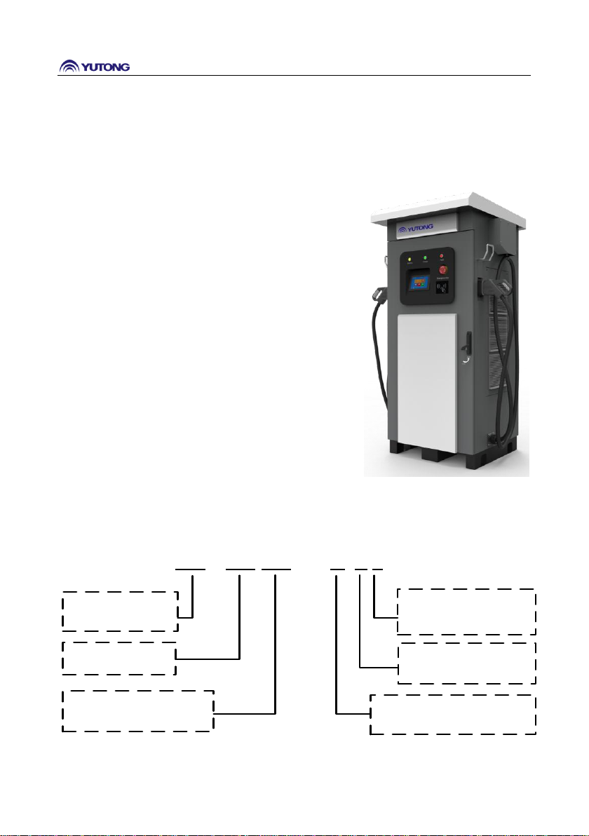
1.1 PRODUCT INTRODUCTION ...................................................................................... 1
1.2 PRODUCT MODEL ................................................................................................ 1
2. PRODUCT MODEL SPECIFICATION ............................................................ 2
3. NORMATIVE REFERENCE AND SPECIFICATION....................................... 3
4. ENVIRONMENTAL CONDITIONS................................................................ 4
5. ELECTRIC CHARACTERISTICS...................................................................... 4
5.1 INPUT CHARACTERISTICS ........................................................................................ 4
5.2 OUTPUT CHARACTERISTICS..................................................................................... 5
5.3 PROTECTION CHARACTERISTICS ............................................................................... 6
5.4 EMC CHARACTERISTICS ......................................................................................... 7
5.5 SAFETY FEATURES ................................................................................................. 8
5.6 OTHER CHARACTERISTICS ....................................................................................... 9
5.7 INDICATOR LIGHT................................................................................................ 10
6. PRODUCT CHARACTERISTICS................................................................... 10
7. DIMENSION AND INSTALLATION............................................................ 11
7.1 DIMENSIONS ..................................................................................................... 11
7.2 INSTALLATION METHOD AND INSTALLATION HOLE SIZE .............................................. 12
8. POWER DISTRIBUTION.............................................................................. 16
8.1 INPUT AC POWER DISTRIBUTION WIRING .............................................................. 16
8.2 OUTPUT DC VEHICLE CONNECTOR PLUG PIN DEFINITION .......................................... 17
9. OPERATION INSTRUCTION ....................................................................... 18
9.1 CHECKS BEFORE CHARGING .................................................................................. 18
9.1.1 Safe checking before charging ............................................................... 18
9.1.2 Attentions in Operation Process............................................................. 18
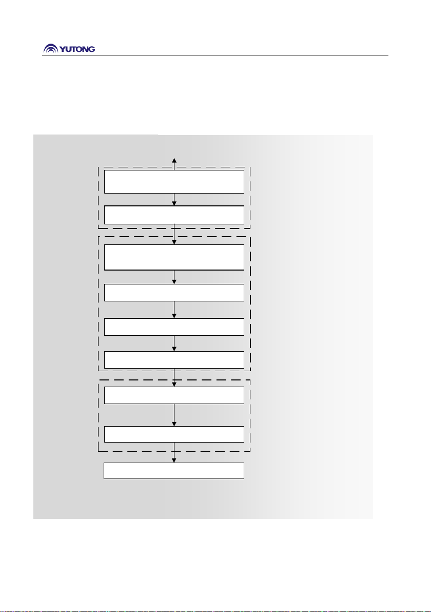
9.2 CHARGING OPERATION FLOW CHART ..................................................................... 19
9.3 CHARGING OPERATION DESCRIPTION ..................................................................... 20

Charging Pile Instructions-V2.0
9.3.1 Charging Operation Instruction............................................................. 20
9.3.2 System Setting......................................................................................... 28
9.3.3 Help........................................................................................................ 35
9.3.4 System Upgrading Instructions .............................................................. 36
9.3.5 Charging Pile Suspended Instructions................................................... 37
9.3.6 Emergency Switch Operation Instructions............................................. 37
10. FAULT ALARM AND TREATMENT .......................................................... 39
10.1 FAULT AND RECOVERY ....................................................................................... 39
10.2 FAULT ALARM AND TREATMENT .......................................................................... 39
11. PACKAGE, TRANSPORTATION AND STORAGE .................................... 43
12. MAINTENANCE AND REPAIR ................................................................. 44

Charging Pile Instructions-V2.0
1
1. Introduction
1.1 Product Introduction
The DC charging pile, which is an isolated DC charging
pile focusing on product safety performance, is
mainly used for quick charging of pure electric vehicles.
Charging piles of this type are designed for outdoor
floor types with waterproof, dustproof and corrosion
proof function and have environmental protection
design with protection grade of IP 54.
The product, with modular design concept, has integrate
the vehicle connector, human-machine interface (HMI),
charger, communication and billing parts together into
one cabinet so that it can easily achieve convenient
installation and debugging, simple operation and
maintenance, etc.
Products could be applied on large-scale parking lots,
residential areas, shopping malls, hospitals, transfer
stations, airports, docks, parks and scenic spots, etc.
1.2 Product Model
HK:
Manufacturer
Code
HK–120-750 –AE 2
1: FirstVersion
2: Second Version
...
120: Power
A: DoubleConnectors
B: Single Connector
C: Four Connectors
E: Europe
750:Output Voltage
Product model

Charging Pile Instructions-V2.0
2
2. Product Model Specification
Model
Output
power
Weight
AC input voltage
Max Input
Current
Output voltage
adjustable range
Output Current
adjustable range
HK-30-750-AE2
30kW
≤400kg
400±15%VAC
(Rated AC
input voltage:
400VAC)
55A
150-750VDC
(Rated DC
Output voltage:
750VDC)
Constant power
range:600-750V
(Max current@
under 600VDC)
0-50A
HK-30/750-BE2
≤390kg
HK-45-750-AE2
45kW
≤410kg
83A
0-75A
HK-45-750-BE2
≤400kg
HK-60-750-AE2
60kW
≤420kg
110A
0-100A
HK-60-750-BE2
≤410kg
HK-60-750-CE2
≤440kg
HK-75-750-AE2
75 kW
≤430kg
138A
0-125A
HK-75-750-BE2
≤420kg
HK-75-750-CE2
≤450kg
HK-90-750-AE2
90 kW
≤440kg
165A
0-150A
HK-90-750-BE2
≤430kg
HK-90-750-CE2
≤460kg
HK-120-750-AE2
120
kW
≤460kg
219A
0-200A
HK-120-750-BE2
≤450kg
HK-120-750-CE2
≤480kg
HK-150-750-AE2
150
kW
≤480kg
274A
0-250A
HK-150-750-BE2
≤470kg
HK-150-750-CE2
≤500kg
HK-40-1000-AE2
40kW
≤405kg
73A
0-40A
HK-40-1000-BE2
≤395kg
HK-60-1000-AE2
60kW
≤415kg
110A
0-60A
HK-60-1000-BE2
≤405kg
HK-60-1000-CE2
≤435kg
HK-80-1000-AE2
80kW
≤425kg
146A
0-80A
HK-80-1000-BE2
≤415kg

Charging Pile Instructions-V2.0
3
HK-80-1000-CE2
≤445kg
400±15%VAC
(Rated AC
input voltage:
400VAC)
150-1000VDC
(Rated DC
Output voltage:
1000VDC)
Constant power
range:800-1000V
(Max current@
under800VDC)
HK-100-1000-AE2
100kW
≤435kg
183A
0-100A
HK-100-1000-BE2
≤425kg
HK-100-1000-CE2
≤455kg
HK-120-1000-AE2
120kW
≤445kg
219A
0-120A
HK-120-1000-BE2
≤435kg
HK-120-1000-CE2
≤465kg
HK-140-1000-AE2
140kW
≤455kg
256A
0-140A
HK-140-1000-BE2
≤445kg
HK-140-1000-CE2
≤475kg
HK-160-1000-AE2
160kW
≤465kg
292A
0-160A
HK-160-1000-BE2
≤455kg
HK-160-1000-CE2
≤485kg
Note:
One vehicle connector working mode:Max Current;
Two vehicle connector working mode: Half max current for DC 1 and Half max current for DC2;
Four vehicle connector working mode: Half max current for DC 1 and DC2, Half max current fou
DC3 and DC4; DC1 and DC2 cannot be used simultaneously;DC3 and DC4 cannot be used
simultaneously.
Each connector will not exceed 200A.
3. Normative Reference and Specification
IEC 61851-1 -2017
Electric vehicle conductive charging system - Part 1: General
requirements
IEC 61851-23-2014
Electric vehicle conductive charging system - Part 23: DC electric
vehicle charging station
IEC 61851-21-2-2018
Requirements for conductive connection of AC/DC power supplies
for electric vehicles-Onboard charging system EMC requirements
IEC 61851-24-2014
Electric vehicle conductive charging system - Part 24: Digital
communication between a DC EV charging station and an electric

Charging Pile Instructions-V2.0
4
vehicle for control of DC charging
IEC 62196-1-2011
Plugs, socket-outlets, vehicle connectors and vehicle inlets –
Conductive charging of electric vehicles –Part 1: General
requirements
IEC 62196-3 2014
Plugs, socket-outlets, vehicle connectors and vehicle inlets –
Conductive charging of electric vehicles –Part 3
DIN SPEC70121:2014
Digital communication of the charging system combined by EV
DC charging system and EV control system
DIN SPEC70122:2018
Digital communication of the charging system combined by EV
DC charging system and EV control system
4. Environmental Conditions
No.
Item
Technical targets
Unit
Remark
Working
Transportation
Storage
1
Temperature
-30~55
-40~70
-40~70
℃
Derating will be
needed above 50℃
2
Humidity
5~95
/
5~95
%
Condensation
free
3
Altitude
≤2500
/
≤2500
m
4
Cooling
method
Forced air cooling
-
5. Electric Characteristics
5.1 Input characteristics
No.
Item
Technical
requirements
Unit
Remark
1
AC input voltage
340~460
VAC
System input line voltage
2
Rated AC input voltage
400
VAC
3P+N+PE
3
AC input frequency range
45~65
Hz
Rated frequency 50Hz/60Hz
4
Power factor
≥0.99
-
Rated input voltage, rated load
5
THD
≤5(The equipment
of Grade A)
%
3P+N+PE
6
AC input system
Three-phase-five-
-
3P+N+PE

Charging Pile Instructions-V2.0
5
wire system
7
Rated Input Current
30kW
47
A
Input 400 VAC, each phase
with full load
40kW
62
45kW
70
60kW
93
75kW
117
80kW
124
90kW
140
100kW
156
120kW
187
140kW
218
150kW
233
160kW
249
5.2 Output characteristics
No.
Item
Technical
requirements
Unit
Remark
1
Voltage error
≤±0.5
%
2
Current error
≤±1
%
Output DC current ≥ 30A
≤±1
A
Output DC current<30A
3
Stabilized voltage precision
≤±0.5
%
4
Stabilized current precision
≤±1
%
5
Ripple factor
Xrms≤1
Xpp≤1
%
6
Current Ripple
1.5
A
f≤10Hz
6
f≤5000Hz
9
f≤150000Hz
7
Efficiency
≥93
%
10-30% of output power
≥94
31-40% of output power
≥95
41-60% of output power
≥94
61-100% of output power
8
Current sharing unbalance
≤±5
%
No less than 4 modules
together50% and above load
9
Current control time
≥20
A/s
10
Current stopping rate
≥100
A/s

Charging Pile Instructions-V2.0
6
5.3 Protection characteristics
No.
Item
Technical
requirements
Unit
Remark
1
Input undervoltage protection point
340
VAC
Adjustable
2
Input overvoltage protection point
460
VAC
Adjustable
3
Inputting phase loss protection
yes
-
4
Input overcurrent protection
yes
-
In case of input overcurrent,
the charging module inside the
equipment tests the input
overcurrent to cut off inputs,
to achieve self protection.
5
Output overvoltage protection
yes
-
Adjustable
6
Output overcurrent protection
yes
-
Adjustable
7
Short-circuit protection
yes
-
8
Over-temperature alarm
50-80
℃
Module inlet temperature is
greater than 50, and automatic
linear reduction in terms of
temperature
9
Over-temperature protection
80
℃
The environmental over
temperature protection point is
80℃. When the DC board
temperature is greater than
85℃, the module will stop
working. When the
temperature of DC board is
lower than 75℃, it can resume
operation automatically
10
Over-temperature alarm of charging
plug
95
℃
Adjustable
11
Over-temperature protection of
charging plug
105
℃
Adjustable
12
Fan opening temperature
Air inlet : >35
℃
Adjustable
Air outlet : >45
13
Temperature protection of air inlet
55
℃
Adjustable
14
Temperature protection of air outlet
75
℃
Adjustable
15
Temperature alarm of air inlet
80
℃
Adjustable

Charging Pile Instructions-V2.0
7
16
Temperature alarm of air outlet
100
℃
Adjustable
17
Emergency shutdown protection
yes
-
Press emergency button, in
case of emergencies.
18
Input inrush current
≤110%
A
Input current
19
Soft-starting time
3~8
S
20
Start output pulse
voltage
≤5%
V
Output DC current ≥ 30A
Output DC current <30A
current
≤5%
≤1.5
A
21
Output current measured error
≤±(1.5%Im+1)
A
Im: actual output current of
charger
22
Output voltage measured error
≤±5
V
23
Measured value update time
≤1
S
24
Output insulation protection
yes
-
In case of 100Ω/V <R<
500Ω/V, the charger sounds an
alarm of abnormal insulation
but still normally charges; in
case of<100Ω/V, the charger
stops charging.
25
Contactor adhesion alarm
yes
-
26
Battery voltage detection function
yes
-
27
Battery voltage reverse function
yes
-
28
Countercurrent protection function
yes
-
29
Door protection function
yes
-
5.4 EMC characteristics
No.
Item
Technical requirements
Remark
1
Conducted disturbance for AC power input port
Pass
2
Asymmetric mode conducted emissions at wired network
port
Pass
3
Conducted disturbance for DC CPT port
Pass
4
Voltage transient disturbance for DC CPT port
Pass
5
Radiated disturbance (2 KHZ TO 185 KHZ)
Pass
6
Radiated disturbance (30MHZ-1000MHZ)
Pass
7
Radiated disturbance (1000MHZ-6000MHZ)
Pass
8
Radio-frequency electromagnetic field amplitude
Pass

Charging Pile Instructions-V2.0
8
modulated (RS)
9
Radio-frequency continuous conducted (CS)
Pass
10
Power-frequency magnetic fields
Pass
11
Fast transients (EFT)
Pass
12
Surge
Pass
13
Electrostatic discharges (ESD)
Pass
14
Voltage dips and interruptions
Pass
Note:Add accessories to pass EMC test
5.5 Safety features
No.
Item
Technical
requirements
Unit
Remark
1
Impulse
withstand
voltage
Input-Earth
≤10
mA
2.8kVDC
Output-Earth
≤10
mA
3.5kVDC
Input -Output
≤10
mA
3.5kVDC
2
Insulation
resistance
Input-Earth
≥10
MΩ
500VDC
Output-Earth
≥10
MΩ
1000VDC
Input -Output
≥10
MΩ
1000VDC
3
Dielectric
strength
Input-Earth
No breakdown
and insulation
damage
-
Thunder electric wave±6KV
Output-Earth
Input -Output
4
Grounding
impedance
The maximum resistance is under
1000 mΩ between the charging
machine and the site.
mΩ
5
Electric
clearance
≥14
mm
6
Creepage
distance
≥16
mm
7
Touch current
≤3.5
mA
8
RCD
YES
-

Charging Pile Instructions-V2.0
9
9
Ac input
lightning
protection
Maximum continuous operating
voltage is 385VAC;
Nominal discharge current is 20kA;
Maximum discharge current is 40kA
Voltage protection level is under
1.8kV
-
5.6 Other characteristics
No.
Item
Technical
requirements
Unit
Remark
1
DC output charging interface
Comply with
IEC62196-3-2014
-
2
Standby power consumption
≤20+5*N
W
N: charging interface quantity
3
Noise
≤65
dB
4
Current display accuracy
≤±1
%
5
Voltage display accuracy
≤±0.5
%
6
IP protection class
IP55
-
7
Cables of the charging gun
10
M
Optional
8
The protection of three
proofing
moisture proofing, salt
spray proofing and
fungus proofing
-
There are several printed circuit
boards in the system. The
connector and other circuits carry
out moisture proofing, salt spray
proofing and fungus proofing
treatment to ensure that the
charger can run normally in the
environment of damp and salt
fog.
9
Antirust protection
Anti oxidation
-
The double layer antirust
measures are taken for the iron
shell of the system and the iron
support and parts exposed
outside. The non iron metal shell
has anti oxidation protection film
or anti oxidation treatment.
10
Environmental protection
Meet requirements of
2011/65/EU; no
cadmium, hydride and
fluoride
-

Charging Pile Instructions-V2.0
10
5.7 Indicator light
No.
Indicator light
Charger state
Standby
Charging
Fault
1
Yellow
ON
OFF
OFF
2
Green
OFF
ON
OFF
3
Red
OFF
OFF
ON
6. Product Characteristics
No.
Item
Technical
requirements
Remark
1
Wireless communication
2G/3G/4G
Different operators are available
2
LAN
Support
Optional
3
Charging card management
system
Support
Complete business card making and card
issuing system, with asynchronous
settlement function
4
Back office management
system
Support
5
Remote upgrading function
Support
6
HMI interaction
Support
LCD display screen equipped
7
Charging record
>1000 pieces
8
Fault record
>1000 pieces
9
Power drop data saving
function
Support
10
Alarming and protection
function
Support
11
APP charging
Support

Charging Pile Instructions-V2.0
11
7. Dimension and Installation
7.1 Dimensions
Figure 7.1 Charging Pile Dimension
Chart 7.1 Detailed Dimension Data of Charging Pile(Unit:mm)
Charging Pile Power
Length
(L)
Width
(W)
Height
(H)
30kW-160kW
900
900
1900

Charging Pile Instructions-V2.0
12
7.2 Installation Method and Installation Hole Size
(1) The charging pile is required to be installed on the cement column that shall be buried in
the ground mostly to ensure safe and stable running, referring to Figure 7.2.1
(2) The charging pile input line entries from the bottom, and enough space shall be reserved
inside cement column.
(3) Four expansion screws shall be used to fix charging pile on the cement column, and the
screw size shall be determined by installation size and based on on-site requirements. Please
refer to figure 7.2.2, chart 7.2.2 and chart 7.2.3 for specific size.
(4) During the installation, enough distance between the charging pile and wall shall be
ensured. The installation distance between the back door of the charging pile and wall shall
be no less than 700 mm, and the distance between the side face of the charging pile and wall
shall be no less than 500 mm.
(5) The canopy shall be built together with the charging pile.
(6) The above installation method is just a sample for reference. Relevant installation
methods shall be chose according to the actual onsite situation Please refer to the
construction instruction for details.
(7) For input lines, specified cables are recommended. See Chart 7.2.1 for details:
Chart 7.2.1 Cables Specification
Output
power
AC Input Voltage
Max. Input
Current
Cable Size Recommended
30kW
400V±15% AC
55A
YJV22-0.6/1kV-3*16mm²+2*10mm²
40kW
400V±15% AC
73A
YJV22-0.6/1kV-3*25mm²+2*16mm²
45kW
400V±15% AC
83A
60kW
400V±15% AC
110A
YJV22-0.6/1kV-3*35mm²+2*16mm²
75kW
400V±15% AC
138A
YJV22-0.6/1kV-3*50mm²+2*25mm²

Charging Pile Instructions-V2.0
13
80kW
400V±15% AC
146A
90kW
400V±15% AC
165A
YJV22-0.6/1kV-3*70mm²+2*35mm²
100kW
400V±15% AC
183A
120kW
400V±15% AC
219A
YJV22-0.6/1kV-3*95mm²+2*50mm²
140kW
400V±15% AC
256A
YJV22-0.6/1kV-3*120mm²+2*70mm²
150kW
400V±15% AC
274A
160kW
400V±15% AC
292A
YJV22-0.6/1kV-3*150mm²+2*70mm²
Note: To ensure the power consumption safety of different onsite, the recommended cable
specification is relatively larger. Customer could choose proper cable according to actual
onsite situation.
(8) For current leakage breaker, specified type is recommended. See Chart 7.2.2 for details:
Chart 7.2.2 Current Leakage Specification
Output
power
Charging pile
User front-end distribution cabinet
Max. Input
Current
Breaker current
leakage setting
Breaker
Recommended
Breaker current
leakage setting
30kW
55A
300mA
(0.03~10A
Adjustable)
≥100
>300mA
40kW
73A
45kW
83A
60kW
110A
≥160A
>300mA
75kW
138A
80kW
146A
90kW
165A
≥250A
>300mA
100kW
183A
120kW
219A
140kW
256A

Charging Pile Instructions-V2.0
14
150kW
274A
≥315A
>300mA
160kW
292A
Note: The recommended breaker and current leakage setting parameter is just for users
reference, actual onsite situation need to be taken into consideration when choosing.
Figure 7.2.1 Construction Drawing
Figure 7.2.2 Concrete Installation Dimension
This manual suits for next models
38
Table of contents