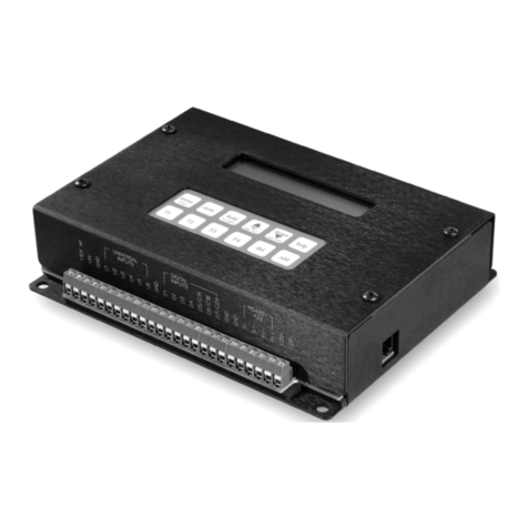
Z-World PK2300 User manual

Users Manual
Revision E
PK2300
C-Programmable Controller

PK2300 Users Manual
Part Number 019-0040
Revision E
Last revised on March 2, 2000 Printed in U.S.A.
Copyright
© 1999 Z-World, Inc. All rights reserved.
Z-World reserves the right to make changes and improvements to its
products without providing notice.
Trademarks
Dynamic C®is a registered trademark of Z-World, Inc.
Windows® is a registered trademark of Microsoft Corporation
PLCBusis a trademark of Z-World, Inc.
Notice to Users
When a system failure may cause serious consequences, protecting life and
property against such consequences with a backup system or safety device
is essential. The buyer agrees that protection against consequences
resulting from system failure is the buyers responsibility.
This device is not approved for life-support or medical systems.
All Z-World products are 100 percent functionally tested. Additional
testing may include visual quality control inspections or mechanical
defects analyzer inspections. Specifications are based on characterization
of tested sample units rather than testing over temperature and voltage of
each unit. Z-World may qualify components to operate within a range of
parameters that is different from the manufacturers recommended range.
This strategy is believed to be more economical and effective. Additional
testing or burn-in of an individual unit is available by special arrangement.
Company Address
Z-World, Inc.
2900 Spafford Street
Davis, California 95616-6800
USA
Telephone:
Facsimile:
Web Site:
E-Mail:
(530) 757-3737
(530) 753-5141
http://www.zworld.com
zworld@zworld.com

Table of Contents siiiPK2300
TABLE OF CONTENTS
About This Manual vii
Chapter 1: Overview 11
PK2300 Overview ...............................................................................12
Features ................................................................................................14
Flexibility and Customization ..............................................................15
Optional Accessories............................................................................ 15
Development Kit ............................................................................. 16
Software Development and Evaluation Tools ......................................16
CE Compliance .................................................................................... 16
Chapter 2: Getting Started 17
Connecting the PK2300 to Your PC .................................................... 18
Running Dynamic C............................................................................. 20
Selecting Communications Rate, Port, and Protocol ......................20
Running a Sample Program ................................................................. 22
Chapter 3: Input/Output Configuration 25
PK2300 Components ........................................................................... 26
Flexible Input/Output Summary........................................................... 27
Configuring Serial Communication ..................................................... 29
Configuring Inputs and Outputs ........................................................... 30
Selecting IN-08 and IN-09, or RMI Input + and - .......................... 30
Selecting IN-12 thru IN-16, or OUT-04 thru OUT-08 ....................31
Selecting IN-10 and IN-11 or RS-485+ and RS-485 .................... 33
CMOS Outputs ................................................................................ 34
Chapter 4: System Development 35
PK2300 Operating Modes ................................................................... 36
Changing the PK2300s Operating Mode ....................................... 37
Running a Program .............................................................................. 38
Using the Digital Inputs/Outputs ......................................................... 39
Protected Digital Inputs .................................................................. 39
How to Read the Inputs ................................................................ 40
High-Current Outputs...................................................................... 42
How to Use the Outputs ................................................................ 42

iv sTable of Contents PK2300
Resistance Measurement Input (RMI) ............................................ 45
How to Use the Resistance Measurement Input ........................... 46
RMI Theory of Operation ............................................................. 49
Serial Communication.......................................................................... 50
RS-232 Communication .................................................................. 50
RS-232 Connector Pinouts .............................................................. 50
RS-485 Communication Network ........................................................ 51
Termination and Bias Resistors ....................................................... 52
Additional Features .............................................................................. 54
PWM Outputs ................................................................................. 54
How to Use the PWM Feature ...................................................... 54
User-Programmable LEDs .............................................................. 58
Memory ........................................................................................... 58
Real-Time Clock (RTC) .................................................................. 59
Power Supervisor ............................................................................ 60
Resetting the Processor ................................................................... 61
PK2300 Subsystems ............................................................................ 62
Chapter 5: Software Reference 63
Supplied Software ................................................................................ 64
Digital Inputs/Outputs ..................................................................... 65
Level-Sensitive Interrupts ............................................................... 68
Interrupt Service Routines (ISR) ..................................................... 69
Resistance Measurement Input........................................................ 70
PWM Outputs ...................................................................................... 72
Additional Software Feature References ......................................... 74
Advanced Input/Output Programming ................................................. 75
Digital Input Addressing Detail ...................................................... 76
Digital Output Addressing Detail .................................................... 77
LED Addressing Detail ................................................................... 78
RS-485 Driver IC Addressing Detail .............................................. 78
Resistance Measurement Input Addressing Detail .......................... 79
PWM Addressing Detail ................................................................. 81
PWM Advanced Programming Functions ....................................... 86
Appendix A: Troubleshooting 89
Out of the Box...................................................................................... 90
Dynamic C Will Not Start .................................................................... 91
Dynamic C Loses Serial Link .............................................................. 91
PK2300 Repeatedly Resets .................................................................. 91
Common Programming Errors ............................................................. 91

Table of Contents svPK2300
Appendix B: Specifications 93
Electrical and Mechanical Specifications ............................................94
PK2300 External Dimensions ......................................................... 95
Factory Default Jumper Positions ........................................................ 96
Protected Digital Inputs ....................................................................... 98
Frequency Response for IN-01 to IN-05, and IN-08 to IN-16........98
Frequency Response for IN-06 and IN-07 ...................................... 99
Customization ................................................................................. 99
Frequency Response and Input Range ..........................................99
Default Pull-Up Assignments .....................................................100
High-Current Drivers ......................................................................... 100
Function of K .............................................................................101
Appendix C: Serial Interface Board 2 103
Introduction........................................................................................ 104
External Dimensions ..........................................................................105
Appendix D: Sinking vs. Sourcing Drivers 107
Selecting Sourcing or Sinking Drivers ............................................... 109
Sinking Driver (Low-Side Drive).................................................. 109
Sourcing Driver (High-Side Drive) ............................................... 110
Appendix E: Power Management 111
Power-Failure Detection Circuitry ..................................................... 112
Power Failure Sequence of Events ................................................ 112
Appendix F: Enclosure Mounting 115
Enclosure Mounting Considerations .................................................. 116
Mounting Controllers on DIN Rails .................................................. 118
Appendix G: Nonvolatile Storage 119
Appendix H: I/O Map and Interrupt Vectors 121
CM7200 Input/Output Map ............................................................... 122
Real-Time Clock Registers ................................................................124
Other Input/Output Addresses............................................................125
Interrupt Vectors ................................................................................126
Interrupt Priorities .............................................................................. 127

vi sTable of Contents PK2300
Appendix I: Battery 129
Storage Conditions and Shelf Life .....................................................130
Instructions for Replacing the Lithium Battery.................................. 130
Battery Cautions ................................................................................131
Index 133
Schematics

About This Manual sviiPK2300
ABOUT THIS MANUAL
This manual provides instructions for installing, testing, configuring, and
interconnecting the Z-World PK2300 controller.
Instructions to get started using Dynamic C®programming functions are
included. Complete C and Dynamic C®references and programming
resources are referenced when necessary.
Assumptions
Assumptions are made regarding the user's knowledge and experience in
the following areas:
Ability to design and engineer the target system that a PK2300 will
control.
Understanding of the basics of operating a software program and
editing files under Windows on a PC.
Knowledge of the basics of C programming.
For a full treatment of C, refer to the following texts.
The C Programming Language by Kernighan and Ritchie
and/or
C: A Reference Manual by Harbison and Steel
Knowledge of basic Z80 assembly language and architecture.
For documentation from Zilog, refer to the following texts.
Z180 MPU User's Manual
Z180 Serial Communication Controllers
Z80 Microprocessor Family User's Manual
$
$

PK2300viii sAbout This Manual
Acronyms
Table 1 lists and defines the acronyms that may be used in this manual.
Icons
Table 2 displays and defines icons that may be used in this manual.
Table 1. Acronyms
Acronym Meaning
EPROM Erasable Programmable Read-Only Memory
EEPROM Electronically Erasable Programmable Read-Only Memory
LCD Liquid Crystal Display
LED Light-Emitting Diode
NMI Nonmaskable Interrupt
PIO Parallel Input/Output Circuit
(Individually Programmable Input/Output)
PRT Programmable Reload Timer
RAM Random Access Memory
RTC Real-Time Clock
SIB Serial Interface Board
SRAM Static Random Access Memory
UART Universal Asynchronous Receiver Transmitter
Table 2. Icons
Icon Meaning Icon Meaning
$
Refer to or see !Note
(Please contact 7LS Tip
Caution
High Voltage
Factory Default
FD

About This Manual sixPK2300
Conventions
Table 3 lists and defines the typographic conventions that may be used in
this manual.
Pin Number 1
A black square indicates
pin 1 of all headers.
Measurements
All diagram and graphic measurements are in inches followed by millime-
ters enclosed in parenthesis.
Table 3. Typographic Conventions
Example Description
while Courier font (bold) indicates a program, a fragment of a
program, or a Dynamic C keyword or phrase.
// IN-01… Program comments are written in Courier font, plain face.
Italics Indicates that something should be typed instead of the
italicized words (e.g., in place of filename, type a file’s
name).
Edit Sans serif font (bold) signifies a menu or menu selection.
. . . An ellipsis indicates that (1) irrelevant program text is
omitted for brevity or that (2) preceding program text may
be repeated indefinitely.
[ ] Brackets in a C function’s definition or program segment
indicate that the enclosed directive is optional.
< > Angle brackets occasionally enclose classes of terms.
a | b | c A vertical bar indicates that a choice should be made from
among the items listed.
J1
Pin 1

PK2300xsAbout This Manual
Blank

PK2300 Overview s11
CHAPTER 1: OVERVIEW
Chapter 1 provides a comprehensive overview and description of the
PK2300. The following sections are included.
PK2300 Overview
Features
Flexibility and Customization
Developers Kit

PK230012 sOverview
PK2300 Overview
PK2300 Series packaged controllers are small, powerful and extremely
flexible system controllers. The PK2300 is programmed using
DynamicC (Z Worlds version of the C programming language).
The PK2300 Series consists of two separate models.
The PK2300 is a full-featured controller that includes all possible
I/O features. It is recommended for initial system development.
The PK2310 is identical to the PK2300, with the following
exceptions.
- The Real Time Clock is not included.
- The Resistive Measurement Input is not included.
As shown in Figure 1-1, the PK2300 is housed in a rugged enclosure that
has multiple mounting options including DIN rail.
Figure 1-1. PK2300 Enclosure, Side View (Left Side)
See Appendix F, Enclosure Mounting, for further details.
Appendix B provides detailed specifications for the PK2300.
The PK2300 is available with either quick-release pluggable terminals or
fixed screw terminals.
$
$

PK2300 Overview s13
Figure 1-2 illustrates the PK2300 board layout.
Figure 1-2. PK2300 Component Layout (Top View, Case Removed)
J3
Battery
Driver
H1
J1
User LED
Optional CMOS
Outputs
H5
Voltage Regulator
H4
I/O Board
J4
Run LED
H3
J2
U1
SRAM
Z180
unde de)(rsi
Flash
EPROM
8-pin
Programming
Header
Real-
Time
Clock
CM7200
Board
H2
(Run/Program)
H10

PK230014 sOverview
Features
The PK2300 includes the following features.
Up to 16 protected digital inputs and as many as 8 CMOS or
high-current driver outputs. Two of the protected digital inputs
have software assignable level sensitive interrupts.
A Resistance Measurement Input (RMI) circuit allows effortless
interfacing to two terminal resistance sensors.
Two serial communication ports are available. Both RS-232 and
RS-485 standards are supported.
Nineteen pins (out of the 24 total) are provided for assigning
various I/O combinations. One RJ-12 modular jack is also
provided for RS-232 communications.
Figure 1-3. PK2300 Top View Showing Screw Terminal Locations
Seven of the digital outputs can optionally provide Pulse Width
Modulation under software control.
To complete the features, our Dynamic C library provides an
assortment of C functions and I/O drivers allowing designers to
easily control the inputs, outputs, and serial channels of the
PK2300 Series controllers.
Four optional 5 V CMOS outputs are accessible via through-hole
pads on the printed circuit board.
Two programmable LEDs.

PK2300 Overview s15
(
(
Flexibility and Customization
The PK2300 was designed with application flexibility in mind. Two levels
of flexibility allow you to select the type of I/O specific to your needs.
Flexibility Level 1 Out of the Box
You can immediately change input and output assignments on
nine of the available 24 terminals. I/O features are assignable via
jumpers allowing quick tailoring to your specific I/O count. In
many cases, this level of flexibility is all thats required.
See Chapter 3, Input/Output Configuration, for further
details.
Flexibility Level 2 Customization
The circuit layout of the PK2300 has been optimized for quick-
turn custom manufacturing. Once your application prototype is
defined, our automatic surface mount manufacturing can deliver
the PK2300 Series controller with the exact hardware your
application requires. Example: Jumper blocks can be configured
and hardwired at the factory.
For details on PK2300 customization, please contact your
Z-World Sales Representative at (530) 757-3737.
Optional Accessories
The following accessories are available for the PK2300.
Development Kit with manual, schematics, programming cable, AC
adapter, and sourcing high-current driver chip
DIN rail mounting kit
Sourcing driver kit
Thermistor that can be used as a rugged temperature sensor
Serial Interface Board to allow programming through a special pro-
gramming port, leaving the serial channels available for the application
For ordering information, or for more details about the
various options and prices, call your Z-World Sales
Representative at (530) 757-3737.
$

PK230016 sOverview
Development Kit
The PK2300 Development Kit includes all the items necessary for soft-
ware and hardware development using the PK2300. The kit includes the
following items.
PK2300 Users Manual (with schematics).
12 V DC wall power supply.
Sourcing high-current drivers, cables, and adapters.
Software Development and Evaluation Tools
Dynamic C, Z-Worlds Windows-based real-time C language development
system, is used to develop software for the PK2300. The host PC down-
loads the executable code through the Serial Interface Board 2 or one of
the serial ports to flash EPROM.
Z-Worlds Dynamic C reference manuals provide complete
software descriptions and programming instructions.
CE Compliance
The PK2300 has been tested by an approved competent body,
and was found to be in conformity with applicable EN and
equivalent standards. Note the following requirements for
incorporating the PK2300 in your application to comply with
CE requirements.
The power supply provided with the Development Kit is for develop-
ment purposes only. It is the customers responsibility to provide a
clean DC supply to the controller for all applications in end-products.
Fast transients/burst tests were not performed on this controller. Signal
and process control lines longer than 3 m should be routed in a separate
shielded conduit.
The PK2300 has been tested to Light Industrial Immunity standards.
Additional shielding or filtering may be required for an industrial
environment.
Visit the Technical Reference pages of the Z-World Web site
at http://www.zworld.com for more information on shielding
and filtering.
$
$

PK2300 Getting Started s17
CHAPTER 2: GETTING STARTED
Chapter 2 provides instructions for connecting the PK2300 to your PC, and
running a sample program on the PK2300. The following sections are
included.
Connecting the PK2300 to Your PC
Establishing Communication with the PK2300
Running a Sample Program

PK230018 sGetting Started
Connecting the PK2300 to Your PC
The PK2300 can be programmed by a PC through an RS-232 port using
the programming cable provided in the Developers Kit.
To connect the PK2300 to a PC:
1. Install Dynamic C as described in the Dynamic C manuals.
2. Connect the 12 V DC power supply to the +DC and GND terminals as
shown in Figure 2-1.
Figure 2-1. Power Supply Connection
Do not plug the transformer into the wall until all the connec-
tions and jumpers have been set.
If a transformer other than the one supplied with the
developers kit is used, ensure that the input voltage specifica-
tions (9 V to 24 V DC) are not exceeded. Appendix B
contains complete specifications for the PK2300.
Use the programming cable supplied with the Developers Kit
to avoid problems with mismatched plugs.
+DC
KGND
Red Shrink Wrap
-
+
PK2300
Power
Supply
Leads
J1
Tip

PK2300 Getting Started s19
3. Ensure that the Run/Program jumper (H2) shown in Figure 2-2 is
installed.
Figure 2-2. Run/Program Jumper Location
Pay particular attention to the installation of the Run/Program
jumper at H2. It is possible to install the jumper so that the
pins are not connected. The PK2300 will not be in Program
Mode if this jumper is installed incorrectly.
4. Establish a serial communication link.
Option 1Via RS-232 Serial Port
Use the adapter and the programming cable supplied with the
developers kit to connect the PK2300s RJ-12 (J2) socket to the
appropriate COM port of your computer. See Figure 2-3.
Figure 2-3. Programming Connections
Run/Program
Jumper
H2
RJ-12
Connector
J2
Programming
Cable
Adapter
PK2300
To PC's
COM
Port
J2

PK230020 sGetting Started
Option 2Via Optional Serial Interface Board 2
The Serial Interface Board 2 (SIB2) is an optional development tool
that allows both of the PK2300s RS-232 ports to be available to an
application. The PK2300 uses a Z-World CM7200 core module as the
microprocessor core. The CM7200 has an additional programming
port, JP1, that connects to the SIB via a 2 mm, 8-pin connector, by-
passing the PK2300s RJ-12 modular jack (J2).
Connect an RJ-12 cable between the SIB2 and the RJ-12/DB9 adapter
attached to the host PC, as shown in Figure 2-4.
Plug the SIB2s 8-pin connector into header JP1 located on the
CM7200.
Observe the polarity of the cable used to connect the SIB2
to JP1. The side of the cable closest to pin 1 is marked in
blue, as indicated in Figure 2-4.
See Appendix C, Serial Interface Board 2, for additional
information on the SIB2.
5. Plug in the transformer to an AC source only after double-checking all
connections. The PK2300 is now ready for programming.
Running Dynamic C
Double-click the Dynamic C icon to start the software. Note that the PC
attempts to communicate with the PK2300 each time Dynamic C is started.
No error messages are displayed once communication is established.
See Appendix A, Troubleshooting, if an error message such
as Target Not Responding or Communication Error appears.
Once the necessary changes have been made to establish
communication between the host PC and the PK2300, use the
Dynamic C shortcut <Ctrl Y> to reset the controller and
initiate communication.
Selecting Communications Rate, Port, and Protocol
The communication rate, port, and protocol are all selected by choosing
Serial Options from Dynamic Cs OPTIONS menu.
The PK2300 supports a communication rate up to 57,600 bps. However,
the Dynamic C software shipped by Z-World may be initialized for a
different rate. To begin, select a communication rate of 57,600 bps.
$
!
$
Table of contents
Other Z-World Controllers manuals