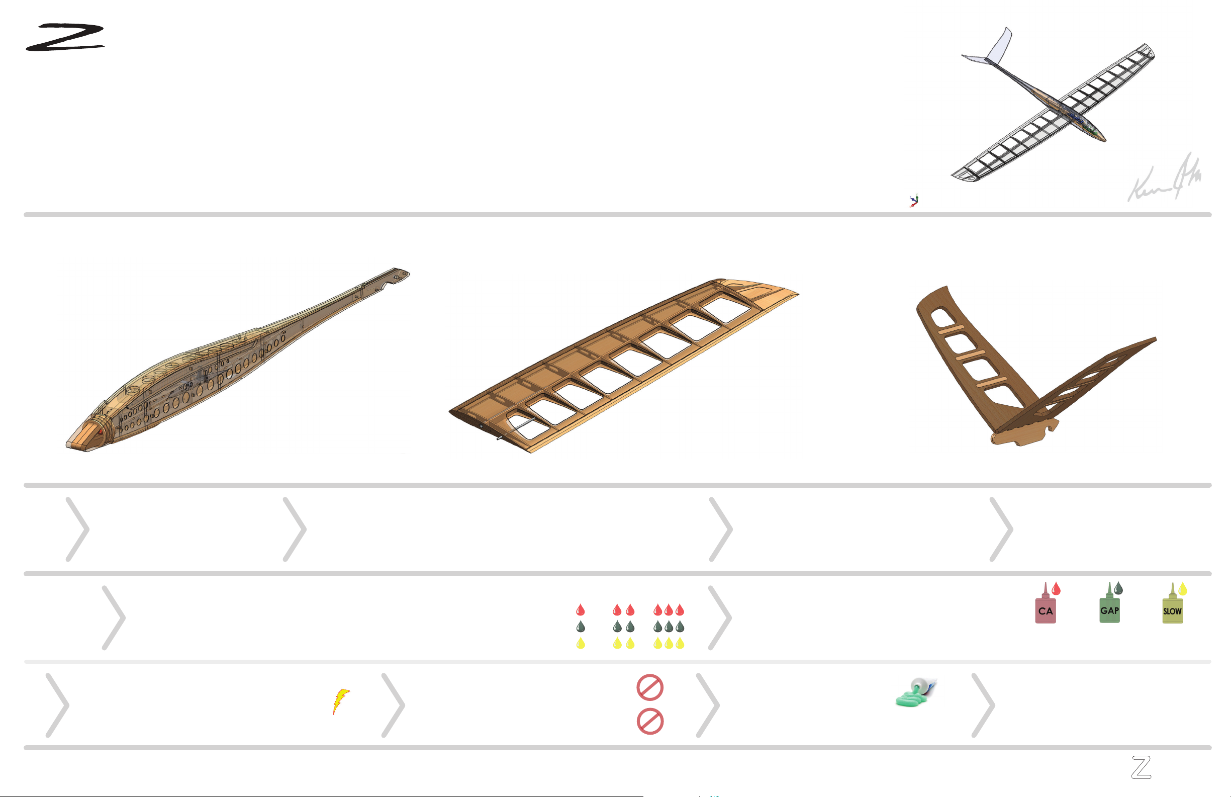
Accelerator
Accelerator
Tail Angle
v2
33
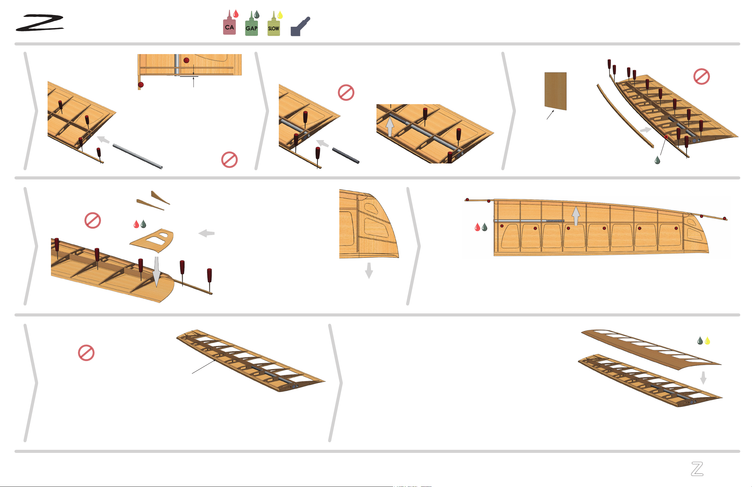
Tail Construction 1
aerotech
Now notice when you view it from behind, the rear cross-brace
carries the Stab angle. You will reference these aids while sand-
ing and adjusting the tabs on the Stab, until you obtain a snug
tab fit and alignment
Carefully fit the Stab and Blade tabs together and let the Stab rest on the Multi-Jig. Check the two angles described above. If
the side rail angle is off, you’ll need to favor either the foreward or aft end of the angle you sanded, effectively tilting the Stab.
The tail angle should be off naturally, requiring you to sand the angle more, effectively moving the Stab down. Take your time,
as this alignment is critical. There is no tail trim on a pitcheron, so tracking is as good as your work. When you get the angle
set, sand the second angle from the tabs so the right stab can be fit. Approximate this angle on the right Stab before fitting
Lightly sand the two Tail Blades on a flat surface with 400
grit sandpaper. Then take a small round object, wrap 400+
grit sandpaper around it, and very lightly sand the capture
radius. Now lightly sand each part, and remove any sharp
edges below the indexing tabs. The tabs will get sanded
later, so no need to prepare them
Capture Radius
The basic theory behind the tail capture design is simple, but it is very
important that you follow the methods here to ensure proper operation.
The wood will cut the O-Rings if engaged before preparation, so take
your time.
Stab Preparation:
Bonding and Finish:Tack the Stabs In-place:
Alignment & Fit:
Slip the foreward end of the Blades into the Tail cavity as
illustrated. The fit should be snug, but not overly tight.
Rotate the aft end down, and stop before you engage the
O-Rings. Again, only snug, but easy to push in and extract
If too tight, sand the blades on a flat surface until they slip
in snug
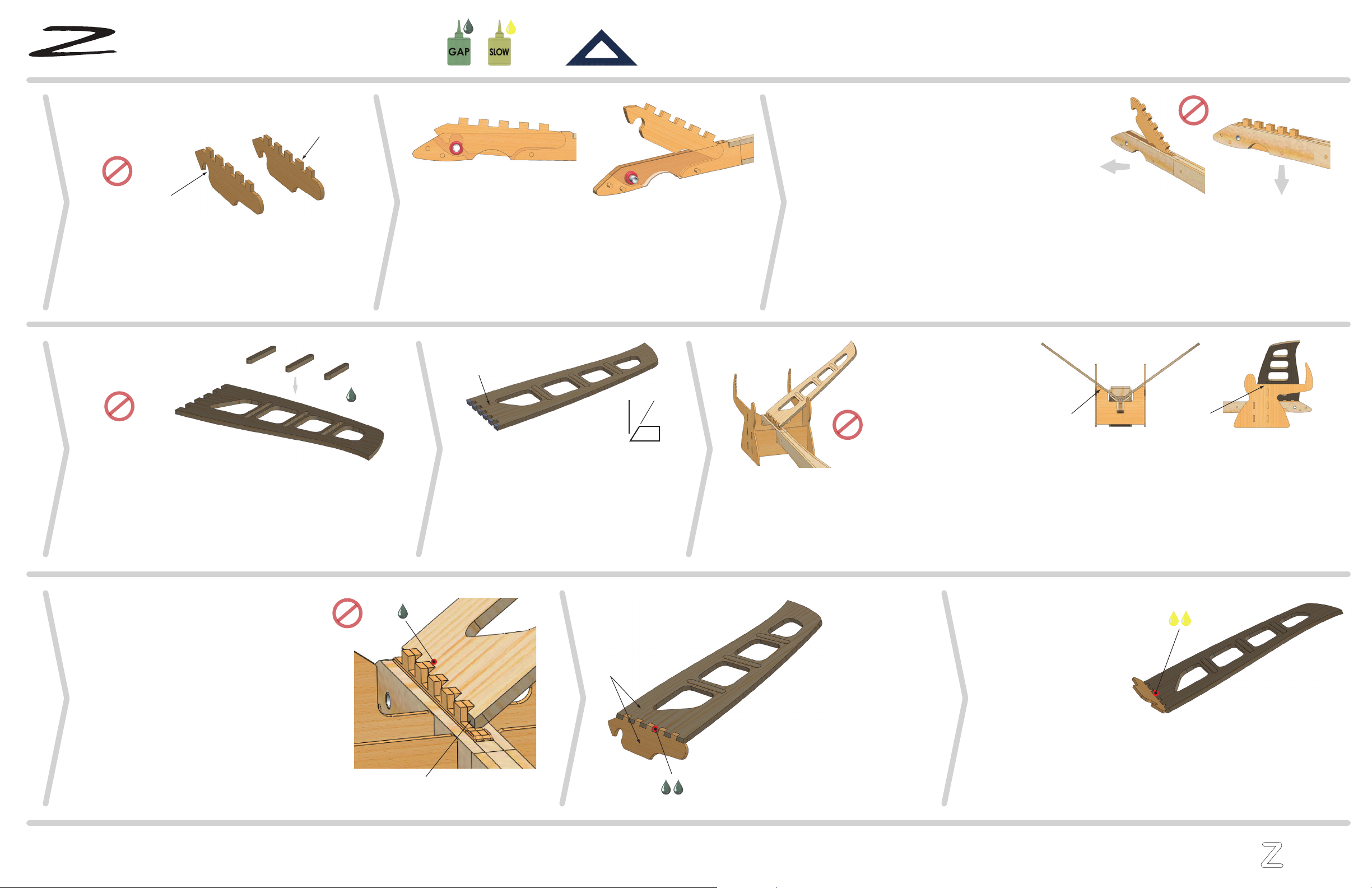
Tail Blade Preparation:
Locate;
- (2)x 1.5mm Ply Tail Blade
Sand each Blade
face to completely
flush the surface to
the Stab tabs. Then
sand the Blade
tabs flush with the
top surface of the
Stab. Finish sand
the entire interface
When you are satisfied with Blades fit, rub a little candle wax on the edge of the Capture Radius. A very small
amount is enough. Rub it in, and remove any excess. Adhesive will not stick to wax, so don’t spread it beyond
the edge of the radius that will engage the O-Rings
Gently rotate the Blades down with your thumb, and apply a little foreward pressure when you feel resistance.
You should feel the capture engaging, and with a little extra pressure, slip home. The top plane of the Blades
should now be parallel to the top plane of the Tail. If not, check for adhesive, debris, sharp corners on the Blade,
etc. You can also sand the capture radius slightly, to move the center up, or to loosen it a bit. But more than
0.5mm in any direction means there is problem elsewhere. To release, apply pressure with your index finger
Stab Bonding:
Tail Latch Theory:
Indexing Tab
Make sure the Tail cavity is clean, and void of any
excess adhesive. Then proceed to the next step
Blade Fitting:
Tail Spline Installation:
Before you remove the Tail parts from the sheet, notice that there
is the side with markings (Cut Side), and a side with laser flash
scorching
Fit the Balsa Spines in their respective holes, with the Stabs “Cut
side” up, and the Spines flashed side up. The laser cuts with a very
slight taper. Flipping the Splines will help the fitting. When flush,
dab some adhesive into the joint
You will be sanding two angles on the index-
ing tab end of each Stab. The first of these
angles (37.5 degrees), illustrated above in
gray, will allow you to set the incidence and
tracking of each stab. You will fit the left
Stab first, and set the alignment as
described in the next step. The second angle
will be sanded in-process to the fit
DO NOT TEST ENGAGE
Bottom
Use only thicker viscosity adhesive for this operation
Above the intersection of each Blade tab, apply one
drop of adhesive where the Stab contacts it
Do this for each tab, then check to make sure you did
not spread adhesive to the opposite Blade
Repeat with the right Stab. Let them cure, then remove
them by using your index finger to eject the tail
Notice by moving the
Multi-Jig fore and aft, you’ll
find a spot where the Stab
will fully fit between the
uprights of the horizontal
rail. Set up the Multi-Jig
and fuselage on a flat
surface and ensure that the
structure is still straight
and not twisted
37.5
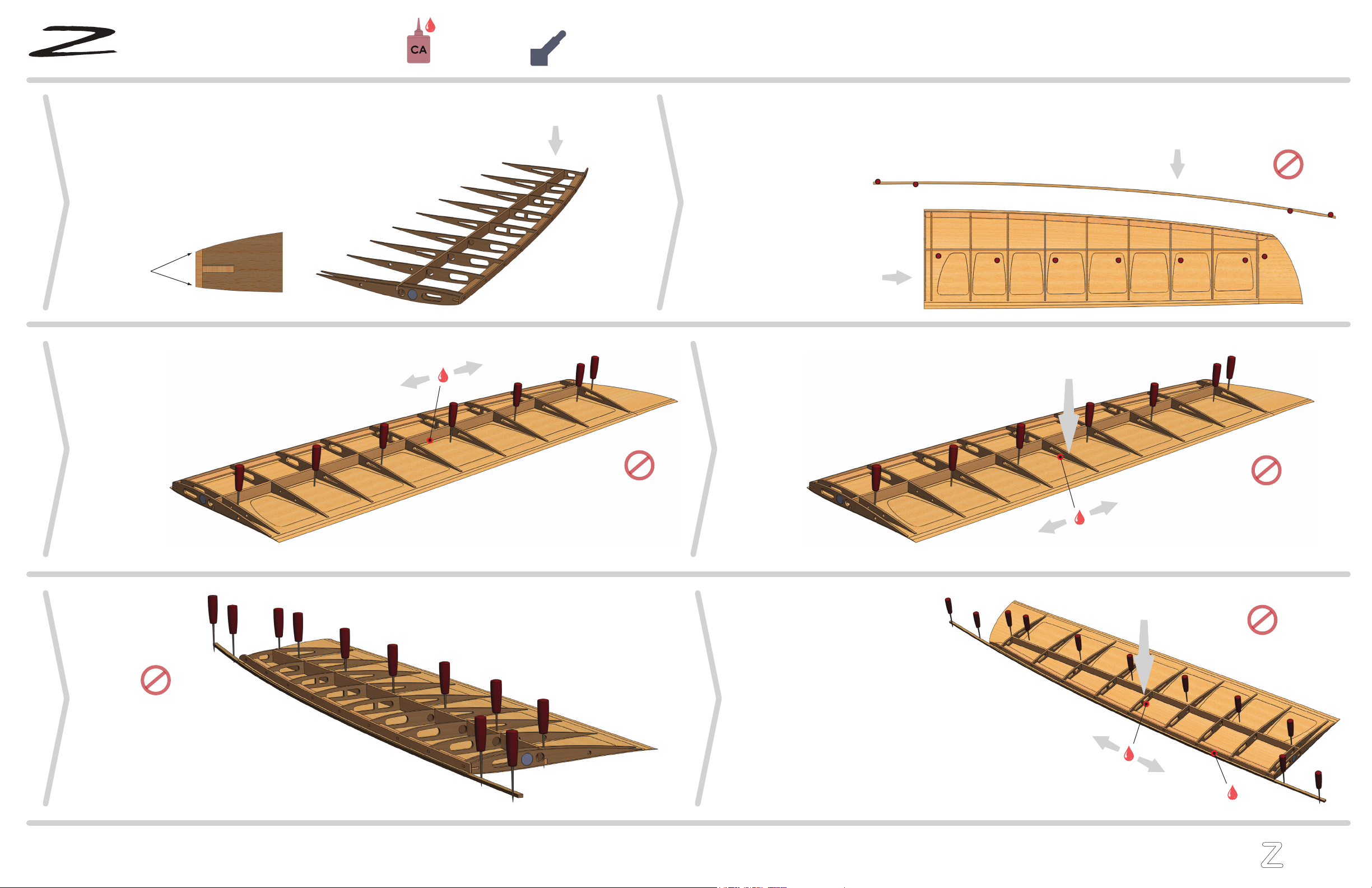
Apply adhesive to the entire interface.
CA or thin epoxy works best to
penetrate the tabs
Add a fillet of adhesive to
the underside interface
Filled epoxy works best.
Alternately SLOW cyano or
thickened wood resin. An
adequate fillet is essential
to a reliable joint
Finish sand both Stabs. Radius the leading edge, and taper the trailing
edge to achieve a smooth surface. Sand as far as you see fit, but leave
at least a 1mm trailing edge thickness for strength
Adhesive
Adhesive
Adhesive
Horz. Rail
Sand Faces
O
Second angle needs to be
sanded before tacking