Zamel RCR-01 User manual

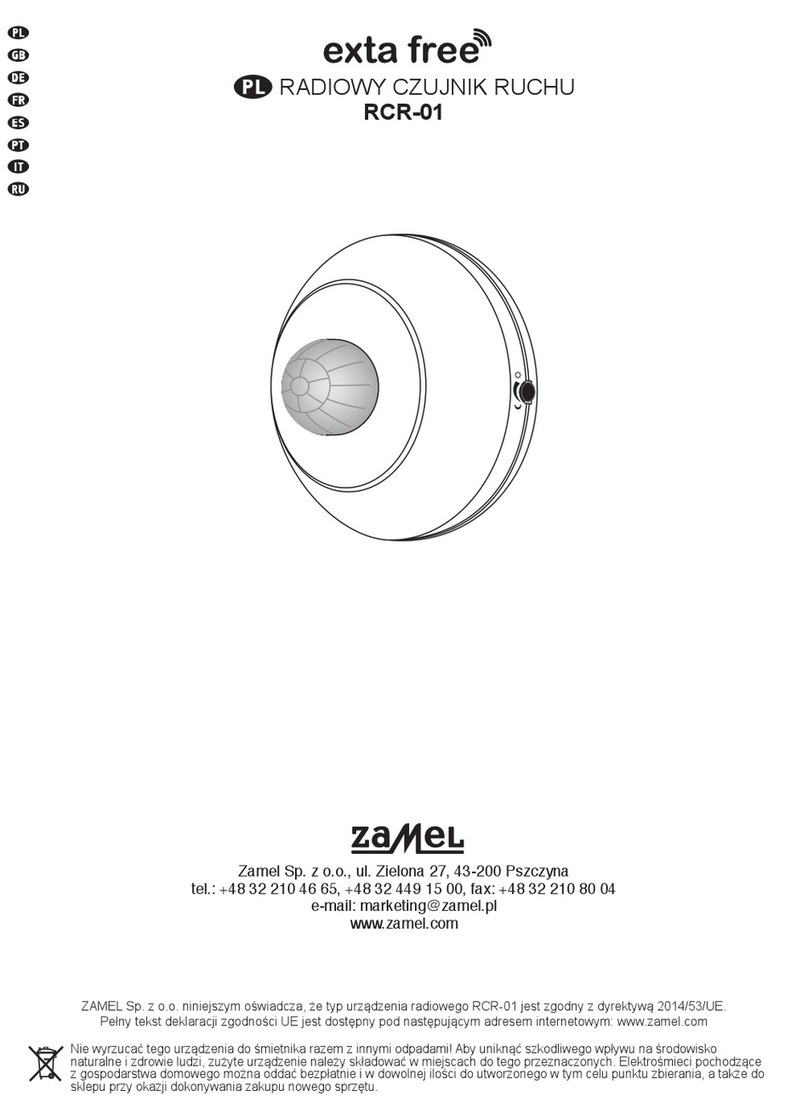
RADIO MOTION SENSOR RCR-01
MANUAL INSTRUCTION
ZAMEL Sp. z o.o.
ul. Zielona 27, 43-200 Pszczyna, Poland
tel. +48 (32) 210 46 65, fax +48 (32) 210 80 04
www.zamelcet.com, e-mail: [email protected]
VER. 003_20.05.2011
TECHNICAL DATA
DESCRIPTION
FEATURES
● (PIR)motionsensorusedinradiocon-
trol of EXTA FREE receivers;
● easyinstallationandmountingbyme-
ans of double-sided adhesive tape
or screws;
● twilightswitchisbuilt-in(motionsensor
operation can be blocked e.g. during
a day);
● sendinginformationandbatterystatus
are optically signalled,
● widerangeofoperation(upto200m);
● possibilityofcooperationwithanynum-
ber of EXTA FREE system receivers;
● possibility of simultaneous switching
on/switching off any number of EXTA
FREE system receivers;
● possibilityofincreasingoperationran-
gebymeansofRTN-01retransmitter.
RCR-01 radio motion sensor is an inde-
pendentbatterypoweredtransmitter.The
sensor detects heat radiation changes
causedby thepresenceormovementof
an object which is in the operation ran-
ge.Aftermovementdetectionthesystem
sends a radio signal to a programmed re-
ceiveroragroupofreceiverswhichcon-
trollighting.Themotionsensorisresistant
totheambienttemperaturechangesand
to air thermal motion. Operation mode
with twilight sensor (with adjusted sensi-
tivity of luminous density measurement)
enablestolimitssensor’soperationrange
tooperationaftertwilight.
Operation range (ceiling mounting)
Angle of view: 60°
Operation range: 2,5 m
APPEARANCE
The symbol means selective
collecting of electrical and electronic
equipment.
It is forbidden to put the used
equipment together with other waste.
Sensitivity potentiometer
PROGpush-button
Optic signalling range of operation
Motion sensor lens
Batterybases
Switchesofoperationmodes
RCR-01
Input rated voltage: 3 V DC
Battery type: 2x AAA / R03
Battery life: 1 year (depending on use)
Numberofchannels: 1
Twilightsensoradjustmentrange: 2 ÷ 20 lx
Transmission: radio 868,32 MHz
Coding way: unidirectional
Coding: addressing transmission
Range: upto200mintheopenarea
Opticsignallingoftransmitter’soperation: LED red diode
Ambienttemperaturerange: -10 ÷ +55 oC
Operating position: free
Casing mounting: wallplugs,double-sidedadhesivetape
Casing protection degree: IP20 (EN 60529)
Protection level: III
Pollution degree: 2
Dimensions: Ø70 x 40 mm
Weight: 0,07 kg
Reference standard: ETSI EN 300 220-1,
ETSI EN 300 220-2
2,5m
3m
APPLICATION
MOUNTING
Thesensor canbe mounted inany placebymeans ofdo-
uble-sidedadhesivetapeorwallplugs5x(3x30)mm.
Mountingbymeansofwallplugs:
1.Removetheuppercover-todoitputascrewdriverintoa
slotbetweenthecoverandthebaseandswitchitliftingup
thecoveratthesametime.
2. Choose a place on the wall to mount the RCR-01 devi-
ce,maketwoholescorrespondingmountingholesfromthe
transmitter’sbase.
3.Setwallplugsintheholes.
4.Fixthebasebymeansoftighteningscrewsintowallplugs.
5. Place the upper cover’s latches into the latches of the
base.
CAUTION: The device has factory mounted batteries se-
cured with special separator. Before the rst device use
remove the separator.
Wirelesslightingoperationsystem.RCR-01sensorsendsaradiocontrolsignal
to ROP-01 receiver after movement detection.
WARRANTY CARD
Thereis24monthsguaranteeontheproduct
1. ZAMEL provides a two-year warranty for its products.
2. TheZAMELwarrantydoesnotcover:a)mechanical defectsresultingfromtransport,loading/unloadingorothercircumstances
b)defectsresultingfromincorrectinstallationoroperationofZAMELproducts;c)defectsresultingfromanychangesmadebyCUS-
TOMERSorthirdparties,toproductssoldorequipmentnecessaryforthecorrectoperationofproductssold;d)defectsresulting
fromforcemajeureorotheraleatoryeventsforwhichZAMELisnotliable;e)powersupply(batteries)tobeequippedwithadevice
inthemomentofsale(iftheyappear);
3. AllcomplaintsinrelationtothewarrantymustbeprovidedbytheCUSTOMERinwritingtotheretailerafterdiscoveringadefect.;
4. ZAMELwillreviewcomplaintsinaccordancewithexistingregulations.;
5. Thewayacomplaintissettled,e.g.replacementoftheproduct,repairorrefund,islefttothediscretionofZAMEL.
6. Guaranteedoes not exclude, does not limit,nor does it suspend therightsof the PURCHASER resulting fromthediscrepancy
betweenthegoodsandthecontract.
Salesman stamp and signature, date of sale
TheZAMELcompany
deviceswhichare
characterisedwiththissign
can cooperate
witheachother.

VER. 003_20.05.2011
OPERATION
PROGRAMMING OF RECEIVERS
BATTERY CHANGE
Thedevicecanoperateintwomodes:1.Motionsensor,2.Motionsensorwithtwilightswitch.Operationmodesareadjustedby
meansoftwoswitcheswhichareunderthetopcoverofthesensor.Mode1-adjusttheswitchto„C”position,Mode2-adjustthe
switchto„F”position.It is important to adjust the switches in the same position, otherwise they operate incorrectly.Inthe
operationmodewithatwilightsensoradjustluminousdensitybymeansofapotentiometer.Potentiometeradjustmentto„ ”sign
meansoperationadjustmentduringdaylight-about20lx,andpotentiometeradjustmentto„ ”signmeansoperationadjustment
duringnight-about2lx.Radiotransmissionrange(upto200m-dependingonareceiver)canbeincreasedbymeansofare-
transmitter or few RTN-01 retransmitters.
Battery discharge status is signalled by several LED red diode ashes during transmission time.
1.Removetheuppercoverofthetransmitter.
2.Removetheupperprinted-circuitboard.
3.Removethebatteries.
4.Mount new batteries. Watch
battery polarisation marked
on the latch. Wrong battery
mounting may cause device
damage.
5.Mount the upper printed-circuit
boardinsertingthepinsintothe
connectors.
6.Mounttheuppercover’slatches
intothelatchesofthebase.
COOPERATION AND OPERATING RANGE
Symbol ROP-01 ROP-02 ROB-01 SRP-02 SRP-03 RWG-01 RWL-01 ROM-01 ROM-10 RDP-01 RTN-01
RNK-02 180 m 200 m 200 m 200 m 200 m 250 m 180 m 250 m 250 m 180 m 250 m
RNK-04 180 m 200 m 200 m 200 m 200 m 250 m 180 m 250 m 250 m 180 m 250 m
P-256/8 230 m 250 m 250 m 250 m 250 m 300 m 200 m 300 m 300 m 230 m 300 m
P-257/4 (2) 180 m 200 m 200 m 200 m 200 m 250 m 180 m 250 m 250 m 180 m 250 m
RNM-10 230 m 250 m 250 m 250 m 250 m 300 m 200 m 300 m 300 m 230 m 300 m
RNP-01 160 m 180 m 180 m 180 m 180 m 200 m 160 m 200 m 200 m 160 m 200 m
RNP-02 160 m 180 m 180 m 180 m 180 m 200 m 160 m 200 m 200 m 160 m 200 m
RNL-01 160 m 180 m 180 m lack* lack* 200 m 160 m 200 m 200 m 160 m 200 m
RTN-01 200 m 200 m 200 m 200 m 200 m 250 m 200 m 250 m 250 m 200 m 250 m
RCR-01 160 m 180 m 180 m lack* lack* 200 m 160 m 200 m 200 m 160 m 200 m
RTI-01 160 m 180 m 180 m 180 m 180 m 200 m 160 m 200 m 200 m 160 m 200 m
RXM-01 230 m 250 m 250 m 250 m 250 m 300 m 200 m 300 m 300 m 230 m 300 m
*-1-channeltransmittersdonotcooperatewithrollerblindcontrollers.
CAUTION: The given range concerns open area - an ideal condition without any natural or articial obstacles. If there are some obstacles between a transmitter and a receiver,
it is advisable to decrease the range according to: wood and plaster: from 5 to 20 %, bricks: from 10 to 40 %, reinforced concrete: from 40 to 80 %,
metal: from 90 to 100%, glass: from 10 to 20 %, Over- and underground medium and high electrical power lines, radio and television transmitters,
GSM transmitters set close to a device system have also a negative inuence on the range.
TRANSMITTERS RECEIVERS
RNK-02
2–channel
buttonradio
transmitter
RNL-01
Radio foot
transmitter
ROP-01
1-channel
radio receiver
RWL-01
Radio
lightingswitch
RNK-04
4-channel
buttonradio
transmitter
RTI-01
IR/EXTA FREE
transceiver
ROP-02
2-channel
radio receiver
RWG-01
Remote
control
socket
P-256/8
8-channel
remote controller
RNM-10
4-channel
radio modular
transmitter
RDP-01
1-channel
radio dimmer
SRP-02
Radio roller
blindscontroller
P-257/4
4-channel
remote controller
RNP-01
4-channel
radio
transmitter
ROB-01/12-24V
Radio
gate controller
SRP-03
Central
radio roller
blindscontroller
P-257/2
2-channel
remote controller
RNP-02
4-channel
radio
transmitter
ROM-01
1-channel
radio modular
receiver
ROM-10
2-channel
radio modular
receiver
RCR-01
Radio
motion sensor
RXM-01
RS485/EXTA
FREE transceiver
ACCESSORIES
ANT-01
External
antenna
RTN-01
Retransmitter
WHEN THE RADIO SIGNALS GO THROUGH OBSTACLES THERE IS OPERATION RANGE DECREASE
bricks 10% to 40 %, wood and plaster 5% to 20 %, reinforced concrete 40% to 80 %, metal 90% to100%, glass 10% to 20%
PressPROGpush-button
of RCR-01, next release
thepush-button.LEDreddiode
switchesonunderthelens
(constant signal).
PressPROGpush-button
of RCR-01device, next
releasethepush-button.
LEDreddiodeswitches
onunderthelens
(constant signal).
Press PROG
push-button
of RCR-01
device again for
a longer time.
PressPROGpush-buttonofRCR-01
deviceandthenreleaseit.
LEDreddiodeinthereceiver
switcheson(signalpulsates),andthen
switchesoff-THESENSORISADDED.
Wait until LED diode
inRCR-01deviceswitchesoff.
ReleasePROGpush-
buttonofRCR-01device.
LEDreddiodeinthe
receiverswitcheson
(rstsignalpulsates,next
thesignalisconstant).
PressPROGpush-button
toadjustthereceiverto
programming mode.
LEDreddiodeinthe
receiverswitcheson
(constant signal).
PressPROGpush-
buttontoadjust
thereceivertothe
programming mode.
LEDreddiodeinthe
receiverswitcheson
(constant signal).
PressPROGpush-button
ofRCR-01deviceandthen
releaseit.LEDreddiodeinthe
receiverswitcheson(rstsignal
pulsates,nextthesignalisconstant).
PressPROGpush-buttonofRCR-01device
andthenreleaseit.LEDreddiodeinthe
receiverswitcheson(signalpulsates),and
thenswitchesoff-THESENSORISADDED.
Wait until LED diode in RCR-01
deviceswitchesoff.
AnexemplaryprogrammingprocedurewiththeuseofRWL-01receiver.
TheprocedurefortherestofradioEXTAFREEtransmittersisanalogous.
Mode 1. Motion sensor (operationmodes’switchesinC-Cposition)
Inthismodethereceivershouldbeprogrammedtooperateintimemode;timeshouldbeadjustedto15seconds.Whenthereisamovement
withindetectionareathedevicesendsasignaltothereceiverevery10seconds.Afterasignalhasbeensent,adjustedtimetiscountedagain.
CAUTION: After each pressing of a push-button in a sensor, there are 10 seconds to start the next programming step. After 10 seconds
LED diode switches off in the sensor and RCR-01 device starts usual operation (programming procedure must be started again.
Mode 2. Motion sensor with twilight switch(operationmodes’switchesinF-Fposition).
Inthismodethereceivershouldbeprogrammedtooperateinmonostablemode.Whenthereisamovementwithindetectionareathe
sensorsendsaswitchonsignaltothereceiver.
Thesensorsendsaswitchoffsignalafter20secondsfromthemomentofnomovementinthedetectionarea.

X-ON Electronics
Largest Supplier of Electrical and Electronic Components
Click to view similar products for Power Management IC Development Tools category:
Click to view products by Zamel manufacturer:
Other Similar products are found below :
EVAL6482H-DISC EVAL-AD5522EBUZ EVAL-ADM1060EBZ EVAL-ADM1073MEBZ EVAL-ADM1166TQEBZ EVAL-
ADM1168LQEBZ EVAL-ADM1171EBZ EVAL-ADM1276EBZ EVB-EN5319QI EVB-EN5365QI EVB-EN6347QI EVB-EP5348UI
MIC23158YML EV MIC23451-AAAYFL EV MIC5281YMME EV 124352-HMC860LP3E ADM00513 ADM8611-EVALZ ADM8612-
EVALZ ADM8613-EVALZ ADM8615-EVALZ ADP1046ADC1-EVALZ ADP1055-EVALZ ADP122-3.3-EVALZ ADP130-0.8-EVALZ
ADP130-1.2-EVALZ ADP130-1.5-EVALZ ADP130-1.8-EVALZ ADP160UJZ-REDYKIT ADP166UJ-EVALZ ADP1712-3.3-EVALZ
ADP1714-3.3-EVALZ ADP1715-3.3-EVALZ ADP1716-2.5-EVALZ ADP1740-1.5-EVALZ ADP1752-1.5-EVALZ ADP1754-1.5-EVALZ
ADP1828LC-EVALZ ADP1870-0.3-EVALZ ADP1871-0.6-EVALZ ADP1873-0.6-EVALZ ADP1874-0.3-EVALZ ADP1876-EVALZ
ADP1879-1.0-EVALZ ADP1882-1.0-EVALZ ADP1883-0.6-EVALZ ADP197CB-EVALZ ADP199CB-EVALZ ADP2102-1.25-EVALZ
ADP2102-1.2-EVALZ
Other manuals for RCR-01
2
Other Zamel Security Sensor manuals