Zamil CX SERIES Instruction manual

INSTALLATION,
OPERATION
&
MAINTENANCE
MANUAL
AIR COOLED CONDENSING UNITS
CX SERIES (CX150 - CX360)
Part Number: 800-213-58 (Rev.-02)

Contents Page
Model decoding ........................................................................................................................................ 2
General statement .................................................................................................................................... 2
Warranty ................................................................................................................................................... 2
Safety issues ............................................................................................................................................ 2
Inspection for damage .............................................................................................................................. 2
Installation procedures ............................................................................................................................. 3
Service clearance ..................................................................................................................................... 3
Dimensions ........................................................................................................................................... 4-6
Rigging & mounting .................................................................................................................................. 7
Refrigerant piping connection ................................................................................................................... 8
Leak testing & refrigerant charging........................................................................................................... 8
Electrical connection ................................................................................................................................ 8
Typical wiring diagram ......................................................................................................................... 9-14
Operating instruction .............................................................................................................................. 15
Maintenance ........................................................................................................................................... 15
Preventive maintenance schedule.......................................................................................................... 16
Troubleshooting................................................................................................................................. 17-18
Parts list ................................................................................................................................................. 19
INDEX
CONTINUING RESEARCH RESULTS IN STEADY IMPROVEMENTS.
THEREFORE, THESE SPECIFICATIONS ARE SUBJECT TO CHANGE WITHOUT NOTICE.
1

1& 2
BASIC 3, 4 & 5
NOMINAL
COOLING
CAPACITY
(MBH)
7
REFRIGERA-
TION CIRCUIT
6
ELECTRICAL
SUPPLY
( V-Ph-Hz )
9
MODE 11
CONDENSER
COIL
CX
CLASSIC
CONDENSING
UNIT
150
180
220
240
300
360
S: SINGLE*
D: DUAL
H: 208/230-3-60
M: 380-3-60
(4 WIRE)
F : 460-3-60
C: COOL ONLY
H: HEAT PUMP+
A:ALUMINUM
FIN
B: COATED
ALUMINUM
FIN
C:COPPER FIN
MODEL DECODING
8
COMPRESSOR
TYPE
S: SCROLL
13
OTHER OPTIONS
10
CONDENSER
MOTOR
N: STANDARD
L: LOW
AMBIENT
12
PDS OPTION
N: NO OPTION
F: STD. UNIT WITH
FILTER DRYER
& SIGHT GLASS
K:
CONDENSING
UNIT WITH
SYSTEMIZER
**
P: PDS***
R :F&K
S :F&P***
T :K&P***
Q : F, K & P***
N: NO OPTION
U: UVM
V: VOLT FREE
CONTACTS
C: U & V
*Applicable for CX150 only.
** To match with double skin units only.
*** Applicable for cool only models.
+Applicable for CX150 to CX220 only. GENERAL STATEMENT
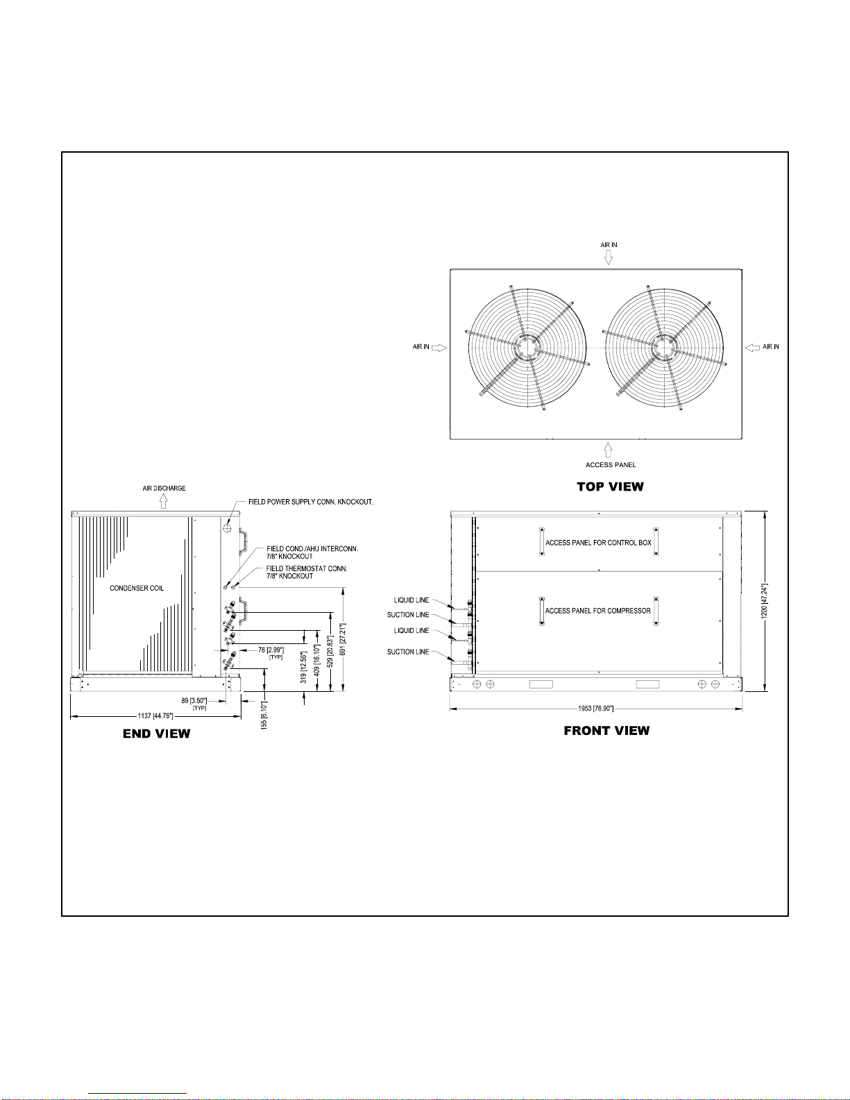
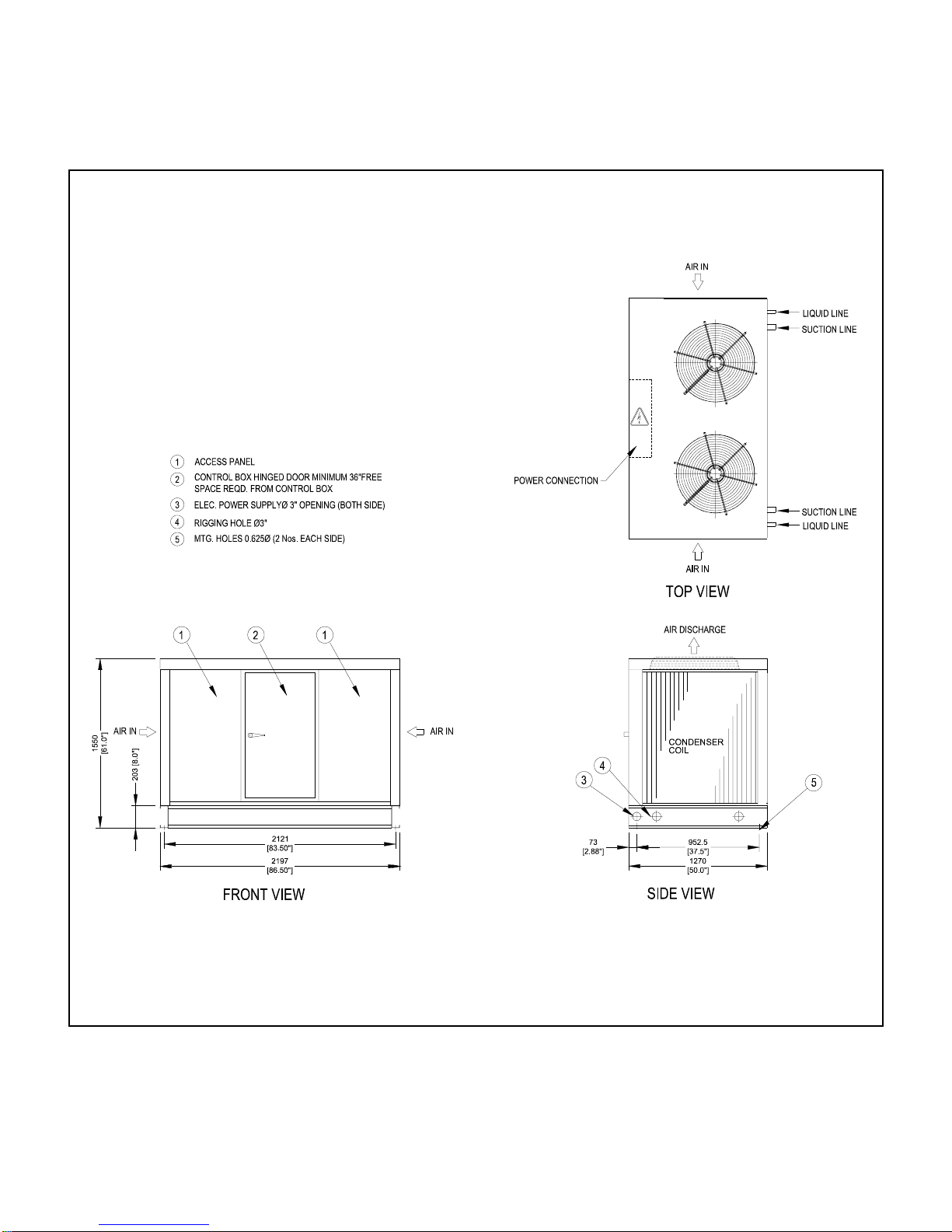
These units are from the Classic CX series that was designed and built for the optimum performance when matched with the
right indoor unit (Refer to indoor unit catalog). However, it is required that you become well acquainted with good practices for
the proper installation, operation, and maintenance procedures in order to ensure a safe trouble free operation, year after year.
Mostof theproceduresdescribedinthis manualrequire certainskills andexperience. Onlyhighly skilledand experienced
technicians should perform the installation and other maintenance procedures.
WARRANTY
All of the Classic CX series are covered by the standard warranty terms against any manufacturer defect. Should you
encounteranyproblemthat fallsunder thewarrantytermspleasecontact yournearest “ZamilClassic” dealer/representative.
SAFETY ISSUES
There are three levels of safety hazards that are identified throughout this manual as Warning (where the situation will
result in personal injury), Caution (where personal injury might occur), and Attention (where minor personal injury and/or
property damage could happen). Please understand and respect those identifications.
WARNING: These units operate on a high voltage with moving parts (at high speed) which can lead to
serious injuries and/or damage to the unit. Never attempt to service the unit unless the main electrical power
supply has been disconnected.
CAUTION: Extra care should be observed when installing, test running, adjusting, servicing, or maintaining
the unit as the hazard of explosion, fire, electrical shock, and potential personal injury and property damage
are present.
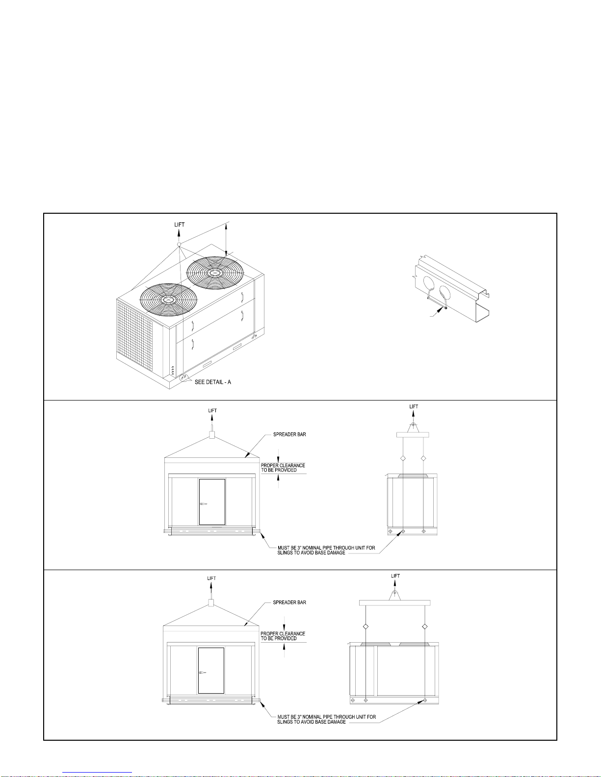
When performing any task pertaining to the installation and maintenance of the unit, the skilled technician should observe
all the applicable safety measures (wear of safety helmet, boots, and goggles. Use of proper handling materials for
brazing and use of wet cloth for sequencing. A fire extinguisher should be easily accessible etc). He should also read all
the instructions and information in this manual prior to attempting to perform any installation or servicing of the unit.
All applicable local codes should be observed during installation and servicing.
INSPECTION FOR DAMAGE
The unit should be carefully inspected visually for any sign of physical damage due to mishandling or missing parts. If
such a case arises, please indicate it on the corresponding delivery note before sign it and inform your nearest “Zamil
Classic” dealer and/or sales office.
2

INSTALLATION PROCEDURES
GENERAL
These units are shipped completely assembled, charged with refrigerant (R-22) and wired. They will require external
power & thermostat wiring in the field. Selection of the condensing unit and its corresponding matching indoor unit
shouldbe basedon aheat calculationmade accordingto applicablestandards. Unitsmustalsobeinstalledin accordance
with regulations of the “National Fire ProtectionAssociation” and local electrical codes. Where local regulations conflicts
with the instructions in this manual, installer should adhere to local standards.
LOCATION OF UNIT
When selecting the location for the unit, the following points should be kept in mind:
1. To provide a concrete pad or steel base that will allow for minimum clearance from building or structures. For
roof mounted unit, be sure that the roof should have sufficient structural strength to carry the weight of the unit.
2. To avoid installing the unit under overhangs.
3. To install the unit in an open area and away from exhaust vents or other source of contaminated air.
4. To have available electrical power.
5. To allow proper drainage away from the unit.
JOBSITE CONDITIONS
a) Check the concrete pad or steel stand for proper dimensions. Refer to attached unit dimensions sketches.
b) Check for proper clearances to allow sufficient space for service access and air circulation as per figure-1 service
clearances.
SERVICE CLEARANCE
FIGURE - 1
MODELS: CX150 - CX360
Note: Allow 96” space above unit.
SINGLE UNIT MULTIPLE UNITS
3

DIMENSIONS
CX150 - CX220
NOTE:
1. All dimensions are in mm (dimensions in brackets are in inches).
4

DIMENSIONS
CX 240 - CX 300
NOTE:
1. All dimensions are in mm (dimensions in brackets are in inches).
5

DIMENSIONS
CX 360
NOTE:
1. All dimensions are in mm (dimensions in brackets are in inches).
943
[37.13"]
943
[37.13"]
2032
[80.0"]
73
[2.88"]
2197
[86.50"]
2121
[83.50"]
1550
[61.0"]
203
[8.0"]
6

RIGGING & MOUNTING
These units are suitable for overhead rigging. See below rigging instructions.
Attention to Riggers:
1. Hook rigging sling through holes/insert 3"nominal pipe through holes in the base rail, as shown below.
2. Holes in base rail are centered around the unit center of gravity.
3. Use wooden pallet or spreader bar when rigging, to prevent the slings from damaging the unit.
Caution: All panels should be in place when rigging. Care must be taken to avoid damage to the coils during handling.
For proper drainage, the condensing unit to be raised off the mounting pad. On roof top applications, locate unit at least
6"(152 mm) above roof surface. Place unit above a load-bearing wall, isolate unit and piping set from structure. Use
4"x4"x1"thick rubber/cork mounting pads.
Arrange supporting members to adequately support unit and minimize transmission of vibration to building.
CX360
STRAP OR SEAMLESS PIPE
BUCKLE
DETAIL - A
2000mm
RIGGING
CX150 - CX220
CX240 - CX300
7

REFRIGERANT PIPING CONNECTIONS
Piping connections:
Outdoor units should be connected to indoor units using field-supplied piping of refrigerant grade and correct size. The
liquid and suction line diameters can be determined from the physical data table. For piping applications beyond 25 feet
(7.62 m), please follow the instructions from ZAC refrigerant pipe sizing manual.
Outdoor unit connected to factory matched indoor unit:
Outdoor unit contain adequate system refrigerant charge for operating with matched indoor unit (as per corresponding
cooling capacity table) and when connected with up to 25 feet (7.62 m) of field-supplied piping.
Sweat connection:
Units are provided with service valves and are ready for brazing. After wrapping the service valve with a wet cloth, the
piping set can be brazed to service valve using either silver rod or silfos rod brazing materials.
LEAK TESTING & REFRIGERANT CHARGING
Leak test :
Leak can occur from joints or fittings that are improperly brazed/connected during installation of indoor and outdoor units.
The installer should leak test the indoor unit & associated field supplied refrigerant piping, then the outdoor unit, each
separately using electronic freon detector and/or soap bubbles.
Refrigerant Charging:
(To be used for system having a holding charge and to compensate for length of liquid line).
1. When system wired, piped and evacuated, the unit is ready for refrigerant charging. All charging lines and manifolds
must be purged with refrigerant vapor prior to admitting refrigerant into the system to prevent contamination system
with non-condensable.
2. It is important to first determine the amount of refrigerant required for the system, the unit nameplate normally identify
the weight of the refrigerant required.
3. The refrigerant should be added in small amounts allowing sufficient time for the unit pressure to equalize each time.
ELECTRICAL CONNECTIONS
Power wiring:
Before making wiring connection, check the electric power supply.
WARNING: Power supply should match exactly with equipment nameplate ratings. Serious damage to
compressors and motors can occur, if improper voltage is applied.
Minimum circuit ampacity for each model is shown on the nameplate and product catalog. Equipment wiring diagram
should be examined and thoroughly understood before field wiring connections are made.
All wiring must comply with “National Electric Code” and local electrical standards.
Control wiring between outdoor & indoor unit:
For control wiring, use 16 gauge color-coded wire between the indoor and outdoor units.
Ground wires:
Connect ground wire to the ground lug inside the control box.
8

TYPICAL SCHEMATIC WIRING DIAGRAM
NOTE: 1. Refer to next page for legend, notes & wiring diagram for optional items.
2. Refer to unit control box (inside panel) for exact wiring diagram.
MODELS : CX150 (SINGLE COMPRESSOR UNITS)
9
CLOSE(PSIG)OPEN(PSIG)
NAME
FCS 190 ± 15 290 ± 10
45LPS1
HPS 450 ± 10
LPS 25 ± 5
55
360 ± 15
50 ± 5
SET POINTS
TRANS2 CONNECTION APPLICABLE FOR 460V UNIT
L1
F1
F3
230V
460V
TRANS2
3
5
4
6F2
F4 L3
PLS. REFER UNIT NAME PLATE
VOLTAGE CONNECT 37A,37B OF
1PH FM & L2 OF TRANS TO NTB
1.NTB IS APPLICABLE FOR
380V/3PH/60Hz
2.FOR UNIT WITH ABOVE
WRG DGM SUITS
230V/3PH/60Hz
460V/3PH/60Hz &
380V/3PH/60Hz
NOTE:
POWER SUPPLY
26A
COMP
T3A
OLR-1 27A
T1A
T2A
SR 2
73A
71A
72A
L3
CC
CC
LUG
HVTB
L3
L2
L1
35A
COMP
CAP1
FM1
CAP2
35B
36A
T1A
T2A
T3A
36B
37A
FM2
37B
73B
72B
71B
71A
72A
73A
OLR1-1
SR-1
COMP.CONN WITH OLR & W/OUT CB OPTION
HVTB
SEE CONN.BELOW
FOR TDS OPTION
TDS1-1SEC
CC1A-1
3A 3C
CC1A-1 3D
3A
L2
L1
3D CC2 226A
CC2
CC1
2
2
T2A
T1A
1
COMP
2A
T1C
T3A
T3C
T2C
OLR2-1 27A
81A SR 2
T3C
T3A
T1C
T2C
T1A
T2A
COMP
1
CB1-1
3E CB2-1
3F 3A
71A
73A
72A
73B
71B
72B
FCS
COMPRESSOR CONNECTION WITH PART WIND START ONLY
WITH CIRCUIT BREAKER
WITHOUT CIRCUIT BREAKER
L3
L2
L1 HVTB
L3
L2
HVTB
L1
CB
L1A71AT1A
CC
LUG
73A
72A
T3A
T2A
COMP 3A
FM1
L3A
L2A
CAP1
35A
36A 37A
CB1
L1A
L3A
L2A
L2B
L1B
L3B
CB2
12 FMC
FM2
2
CAP2
35B
36B 37B
FMC
T2A/72A
LOW AMBIENT OPTION CONNECTION
APPLICABLE FOR 230V - 1PH FAN MOTOR
CIRCUIT BREAKER OPTION
HVTB L1
L2
L3
TO CC
T1A/71A T3A/73A
TOCC
T2A/72A
AHU
TO
41A USE FOR OPTION-3-B ONLY
5
4
3
2
39A
38A
1
ATB
SR-2 40A
15 CB 16
24VAC
C-PUMP DOWN SOLENOID RELAY
17
YR
PDSR
C-COOLING RELAY
JP1
[UVM]
1F2
*[SSPS] [AI]
FOR COMP.CONN.WITH PART WIND START-SEE ABOVE
JP4
PDSR-1
TRANS1
YR-1
LPS
2A
24A
4A
JP6
SR-1
25A
3A
26A
ATB1
SEE HPS OPTION BELOW
JP2
1A
[SD]
1B F1 230VAC
SEENOTE-8
L1 L2
C-PUMP DOWN SOLENOID
PDS
C-CONTROL RELAY
CR
CC
SR
C-CONTACTOR
C-SAFETYRELAY
ATB12
NTB

TYPICAL SCHEMATIC WIRING DIAGRAM
15
UNIT OFF
FR
COMP
17
AR1-1
46
AR1
47
17
CONN.FOR OIL PRESSURE SWITCH OPTION
CR-1128A
26A/27A OPS
2
2240
28C
OPS
SR 2
(PLS. CONNECT LPS ACCORDINGLY)
5A
NOTE:
AR8
ONE UNLOADER
LPS1
3A 6A UL
AR8-1
1
22
1) UVM OPTION
OPTIONS
2) SMOKE DETECTOR OPTION
UVM-1 81
REMOVEJP2
VFC-FROM CUSTOMER'S
SMOKE DETECTOR
1A 1B
(REMOVE JP1)
1A
TO ATB
TOATB 1
Ø Ø
L2
L1
Ø
L1
L3
Ø
L2
ØUVM
L3
REMOVEJP4
12
(SEENOTE6)
COMP
CONNECTION FOR COMP. WITH SSPS
SSPS
4. HPS OPTION
CCA-1B IS CC1A-2B
TO
LPS
43
23A HPS 24A
UNIT-TRIP
FR-1 44
C-ON
FOR PWS CCA-1A IS CC1A-2A &
55
CCA-1B
57
C-OFF
C-TRIP
56 58
54
CCA-1A
FR-2
FR-2
AR1-1
UNIT ON
UNIT TRIP INDICATION OPTION
B) COMP ON, OFF & TRIP [&]
A) UNIT ON & OFF INDICATION
ATB
41A
45
UNLOADER CIRCUIT CONNECTION FOR COMP WITH
BITZER COMP: FULLY LOADED WHEN UL IS DE-ENERGIZED
COPELAND COMP:-FULLY LOADED WHEN UL IS ENERGIZED
CRANKCASE HTR CONNECTION FOR SEMI HERMETIC
COMPRESSOR ONLY
CRANKCASE HTR CONNECTION
MODELS : CX150 (SINGLE COMPRESSOR UNITS)
NOTES
1. POWER SUPPLY, REFER TO UNIT NAMEPLATE.
2. ANY WIRE REPLACEMENT SHOULD BE OF THE 900C
OR ITS EQUIVALENT.
USE COPPER CONDUCTOR WIRES ONLY.
3. POWER MUST BE SUPPLIED TO CRANKCASE
HEATER FOR MINIMUM OF 12 HOURS PRIOR TO
SYSTEM START UP.
IF POWER IS OFF 6 HOURS OR MORE, CRANKCASE
HEATER MUST BE ON FOR 12 HOURS BEFORE
OPERATING THE SYSTEM.
FAILURE TO FOLLOW THESE INSTRUCTIONS MAY
RESULT IN COMPRESSOR DAMAGE.
4. FUSED DISCONNECT SWITCH OR CIRCUIT
BREAKER TO BE PROVIDED BY END USER WITH
RATING AS RECOMMENDED BY ZAMIL.
5. IF PDS IS FACTORY INSTALLED, PLEASE READ
BROKEN LINES AS CONTINUOUS LINES.
6. ALLOW 2-3 MINUTES FOR SSPS SWITCH TO CLOSE,
BEFORE STARTING THE UNIT.
7. USE DISCONNECT TAB OR SPLICE ONLY WHERE
EVER REQUIRED FOR EXTENSION OF ORIGINAL
WIRE.
8.
REMOVE JUMPER FOR AI OPTION. ROUTE AI
WIRES FROM AHU.
9. FOR UNITS HAVING COMP. OLR, FM WIRES 36A &
36B TO BE CONNECTED TO 71A & 72A AND 37A &
37B TO BE CONNECTED TO 72A & 73A RESPEC-
TIVELY.
LEGEND
AHU AIR HANDLING UNIT
AI ANTI ICE THERMOSTAT
AR AUXILIARY RELAY
ATB AUXILIARY TERMINAL BLOCK
CAP CAPACITOR
CC COMPRESSOR CONTACTOR
CB CIRCUIT BREAKER
C. HTR CRANKCASE HEATER
COMP COMPRESSOR
CR CONTROL RELAY
FM FAN MOTOR (CONDENSER)
FMC FAN MOTOR CONTACTOR
FR FAULT RELAY
FCS FAN CYCLING SWITCH
HPS HIGH PRESSURE SWITCH
HVTB HIGH VOLTAGE TERMINAL BLOCK
JP JUMPER
L1 LINE 1
L2 LINE 2
L3 LINE 3
LPS LOW PRESSURE SWITCH
LUG LUG GROUND
NTB NEUTRAL TERMINAL BLOCK
OPS OIL PRESSURE SWITCH
OLR OVER LOAD RELAY
PDS PUMP DOWN SOLENOID
PDSR PUMP DOWN SOLENOID RELAY
RR RESET RELAY
SD SMOKE DETECTOR
SSPS SOLID STATE PROTECTION SYSTEM
TDS TIME DELAY SWITCH
TRANS TRANSFORMER
T'STAT THERMOSTAT
UL UNLOADER SOLENOID
UVM UNDER VOLTAGE MONITOR
VFC VOLT FREE CONTACT
YR COOLING RELAY
FIELD WIRING
DISCONNECT TAB - 1/4"
SPLICE-CLOSED END
_ _ _
+
10

TYPICAL SCHEMATIC WIRING DIAGRAM
11
1
LPS1
JP1 1A
2A
ATB1
JP2 1B F1
T3A
COMP
1
T2A
T1A
CC1
FM1
36A
35A
37A
T2B
T1B
FMC1
SR1-1
[SSPS2]
JP7 25B
[SSPS1]
230VAC
JP4
L1
25A
L2
3A
JP8
*26B
4A
JP6
SEE NOTE-8
*
F2
26A
T3B
FM2
35B
37B
36B
CC2 FMC2
C1-CONTACTOR
C1-SAFETY RELAY
C2-SAFETY RELAY
C1-PUMP DOWN SOLENOID
C1-CONTROLRELAY
SR2
CR1
PDS1
ATB1
SR1
CC1
2
SEE HPS OPTIONBELOW
SEE HPS OPTIONBELOW
TRANS2 CONNECTION APPLICABLE FOR 460V UNIT
5
F3
F1
L1 3
TRANS2
F4
F2
6
230V
1
2
5
4
6
7
8
3
TOAHU
USE FOR OPTION-3-B ONLY
(FOR FCS CONNECTION SEE LOW AMBIEMT OPTION)
16
ATB
15 CB
CR2-1
YR2-1
PDSR2-1
CCA2-1
CCA1-1
2B
24VAC
SR1-2
SR2-2
41A
39B
41B
38A
38B
39A
40B
40A
TRANS1
SR2-1
12B
3B
12A
4B
C2-PUMP DN SOLENOID RELAY
C1-PUMP DN SOLENOID RELAY
17
C2-COOLING RELAY
C1-COOLING RELAY
YR2
PDSR2
YR1
PDSR1
C2-CONTACTOR
C2-CONTROLRELAY
C2-PUMP DOWN SOLENOID
FAN MTR1-CONTACTOR
FAN MTR2-CONTACTOR
FMC2
PDS2
FMC1
CC2
CR2
LUG
L2
L3
HVTB L1
[AI2]
[AI1]
[SD][UVM]
24A
24B
COMP
2
CR1-1
PDSR1-2
YR1-1
LPS2
460V 4L3
1PH FM & L2 OFTRANS TO NTB
VOLTAGE CONNECT 37A,37B OF
2.FOR UNIT WITH ABOVE
380V/3PH/60Hz
1.NTB IS APPLICABLE FOR
380V/3PH/60Hz
460V/3PH/60Hz
230V/3PH/60Hz
WRG DGM SUITS
PLS. REFER UNIT NAME PLATE
POWER SUPPLY
NOTE:
NTB
NOTE: 1. Refer to next page for legend, notes & wiring diagram for optional items.
2. Refer to unit control box (inside panel) for exact wiring diagram.
MODELS : CX180 - CX220 (DUAL COMPRESSOR UNITS)

LEGEND
AHU AIR HANDLING UNIT
AI ANTI ICE THERMOSTAT
AR AUXILIARY RELAY
ATB AUXILIARY TERMINAL BLOCK
CAP CAPACITOR
CC COMPRESSOR CONTACTOR
CB CIRCUIT BREAKER
C. HTR CRANKCASE HEATER
COMP COMPRESSOR
CR CONTROL RELAY
FM FAN MOTOR (CONDENSER)
FMC FAN MOTOR CONTACTOR
FR FAULT RELAY
FCS FAN CYCLING SWITCH
HPS HIGH PRESSURE SWITCH
HVTB HIGH VOLTAGE TERMINAL BLOCK
JP JUMPER
L1 LINE 1
L2 LINE 2
L3 LINE 3
LPS LOW PRESSURE SWITCH
LUG LUG GROUND
PDS PUMP DOWN SOLENOID
PDSR PUMP DOWN SOLENOID RELAY
RR RESET RELAY
SSPS SOLID STATE PROTECTION SYSTEM
SD SMOKE DETECTOR
TRANS TRANSFORMER
T'STAT THERMOSTAT
UVM UNDER VOLTAGE MONITOR
VFC VOLT FREE CONTACT
YR COOLING RELAY
FIELD WIRING
DISCONNECT TAB - 1/4"
SPLICE-CLOSED END
TYPICAL SCHEMATIC WIRING DIAGRAM
_ _ _
+
NOTES
1. POWER SUPPLY, REFER TO UNIT NAMEPLATE.
2. ANY WIRE REPLACEMENT SHOULD BE OF THE 900C
OR ITS EQUIVALENT.
USE COPPER CONDUCTOR WIRES ONLY.
3. POWER MUST BE SUPPLIED TO CRANKCASE
HEATER FOR MINIMUM OF 12 HOURS PRIOR TO
SYSTEM START UP.
IF POWER IS OFF 6 HOURS OR MORE, CRANKCASE
HEATER MUST BE ON FOR 12 HOURS BEFORE
OPERATING THE SYSTEM.
FAILURE TO FOLLOW THESE INSTRUCTIONS MAY
RESULT IN COMPRESSOR DAMAGE.
4. FUSED DISCONNECT SWITCH OR CIRCUIT
BREAKER TO BE PROVIDED BY END USER WITH
RATING AS RECOMMENDED BY ZAMIL.
5. ATB (3) & (5) IS APPLICABLE FOR PDS OPTION UNITS
ONLY.
6. ALLOW 2-3 MINUTES FOR SSPS SWITCH TO CLOSE,
BEFORE STARTING THE UNIT.
7. USE DISCONNECT TAB OR SPLICE ONLY WHERE
EVER REQUIRED FOR EXTENSION OF ORIGINAL
WIRE.
8.
REMOVE JUMPER FOR AI OPTION. ROUTE AI
WIRES FROM AHU.
MODELS : CX180 - CX220 (DUAL COMPRESSOR UNITS)
23A
23ATO
LPS1
LPS2
TO
HPS1
HPS2
24A
24A
5. HPSOPTION
COMP2:
COMP1:
CONNECTION FOR COMP. WITH SSPS
CRANKCASE HTR CONNECTION
(SEE NOTE 6)
REMOVEJP7
SSPS2
REMOVE JP4
SSPS1
1
M1/11
L1/MP
1
M1/11
L1/MP 2
L2/R
M2/14
2
M2/14
L2/R
C2-TRIP
C2-OFF
FR1-1
43
C2-ON
60
CC2A-2A
61
FR2-1
UNIT-TRIP
44A
62
CC2A-2B
44
63
A) UNIT ON & OFF INDICATION
UNIT TRIP INDICATION OPTION
B) COMP ON, OFF & TRIP [&]
3. VOLT FREE CONTACT OPTIONS
2. SMOKE DETECTOR OPTION
55
1741A
FR2-2
FR2-2
C1-TRIP
C1-OFF
ATB(8)
41B
59
FR2
COMP2
FR1-2
FR1-2
56
C1-ON
CC1A-2A
57
CC1A-2B
54
FR1
17
58
VFC-FROM CUSTOMER'S
AR1-1
UNIT OFF
AR1
ATB(7)
UNIT ON
45 AR1-1
15
COMP1
46
17
REMOVE JP2
SMOKE DETECTOR
1A
47
1B
SET POINTS
1. UVM OPTION
HPS1&2
LPS1&2
NAME
360 ± 15
50 ± 5
(PSIG)
CLOSEOPEN
(PSIG)
450 ± 10
25 ± 5
FOR 3PH FAN MOTOR ONLY
4. LOW AMBIENTOPTION APPLICABLE
CC1A-1
CC2A-1
CB1
CC1
LUG
L3
COMP
1FM1
FMC1
T3A
T2A
T1A
L3A
L2A
L1A
35A
36A
37A
COMP
2
L3B
T3B
CC2
T1B
T2B
CB2
L1B
L2B
FMC2
35B
FM2
ATB2
37B
36B
1
CONNECTION APPLICABLE FOR 1PH FAN MOTOR ONLY
CIRCUIT BREAKER OPTION
L1/L1A
CAP1
35A
36A
HVTB
L2
L1
FMC1
36A
37A
FM1
L2/L2A
FMC2
35B
CAP2
36B
FM2
36B
37B
L2/L2B L3/L3B
FMC1
35A L1
ATB2
FM2
FCS1
FCS2
12B
12A
FM1
FMC1
13 FMC2
FAN1 CONTACTOR
FAN2 CONTACTOR
2
36A
37A
L2
L3
FMC2
35B
36B
TOHVTB
37B
UVM
ØØØ
1
TO ATB 1A
TO ATB
(REMOVE JP1)
ØUVM-1
1Ø
8
L1 L2 L3
12

TYPICAL SCHEMATIC WIRING DIAGRAM
NOTE: 1. Refer to next page for legend, notes & wiring diagram for optional items.
2. Refer to unit control box (inside panel) for exact wiring diagram.
MODELS : CX240 - CX360 (DUAL COMPRESSOR UNITS)
13
27B
OLR2-1
OLR1-1 27A C1-SAFETY RELAY
TO
AHU
[AI2]
FOR FANMOTORS CONNECTIONS
SEE FAN MOTOR CONNECTION DIAGRAM
2
8
6
7
4
5
3
1
USE FOR OPTION-3-B ONLY
41B
41A
YR2 C2-COOLING RELAY
YR1 C1-COOLING RELAY
ATB TRANS1
230V
CB
15 17
LPS2 [SSPS2]
FOR COMPRESSOR CONNECTIONS
WITH PART WIND START-SEE ABOVE
SR2-1
JP8
2B
JP7
24B 25B
3B
26B
C2-CONTROL RELAY
CR2
C2-SAFETY RELAY
C2-CONTACTOR
CC2
SR2
FOR COMPRESSOR CONNECTIONS
WITH PART WIND START-SEE ABOVE
SR1-1
2A 3A
C1-CONTROL RELAY
CC1 C1-CONTACTOR
CR1
CONNECTIONS SEE BELOW
[AI1]
[UVM] [SD]
LPS1
JP1
11A ATB1
1B
JP2
SEE NOTE-8
[SSPS1]
24A 25A
JP4
L1D
L3B
L2D
2
2
CC2
CC4
2
2
CC4
SR2
3E
T3D
3E
T1D
T3B
COMP
3I
CB4-1
2
T2D
CC2A-2
CC2A-2
OLR2-1 81B
3F
OLR4-1
TDS2-1SEC
SEECONN.BELOW
FOR TDS OPTION
27B
L2B
L1B
L2C
L1C
L2A
L1A
L3A
L3C
T2B
T1B
3H
CB2-1
2
2
3B
3I
26B
T2C
T1C
COMP
1
T2A
T1A
T3A
3D
FOR TDS OPTION
SEE CONN .BELOW
CC3
SR1
27A
3D
T3C
CC1
CC3
2
2
HVTB
3G
CB3-1
CB1-1 3F
3C
81A
3G
26A
CC1A-2
OLR1-1
3A
TDS1-1SEC
CC1A-2
OLR3-1
21FMC2A-1
FMC1A-1 FMC3
13A 2
FM3
104
106
105
107
102
103
FM2
37A
36B
35B
FMC2
37B
35C
36C
FMC3
L2
CB6
L1 L3
108
37C
2. 3FM CONNECTION:
FAN MOTOR CONNECTIONS - STANDARD
1. 2FM CONNECTION: [CX240/300] [CX360]
ATB2
ATB2
CR2-2
CR1-2
1FCS2
FCS1
12A
12 FMC1
FMC2
13 2CONTACTOR
CONTACTOR
FAN1
FAN2
POWER SUPPLY
PLS. REFER UNIT NAME PLATE
WRG DGM SUITS
230V/3PH/60Hz
460V/3PH/60Hz
380V/3PH/60Hz
NOTE:
1.NTB IS APPLICABLE FOR
380V/3PH/60Hz
2.FOR UNIT WITHABOVE
VOLTAGE CONNECT L2 OF
TRANS TO NTB
L1
TRANS2
5
3
F1
F3 460V
230V
F2
F4
6
4L3
TRANS2 CONNECTION APPLICABLE FOR 460V UNIT
35A
36A
FMC1
100
101
FM2
1
CR2-2
CR1-2
FMC2
37A
36B
37B
35B
102
104
105
103
FMC1
2
35B
36B
37B
35C
35A
36A
37A
FMC1
FMC2
13
1
2
FM1
FMC2A-1
FMC1A-1
FCS2
FCS1
12A
FM2
FMC2
101
102
100
FMC3
105
104
103
106
36C
37C
FMC3
13A 2
FM3
108
107
FM1
FMC1
2. 3FM CONNECTION:
FAN MOTOR CONNECTIONS - LOW AMBIENT OPTION
FMC1
L2
1. 2FM CONNECTION:
L1
CB6
CR1-2
112
[CX240/300]
L3
FMC2
CR2-2
21 13 CR1-2
21 12
L2
FM1
100
101
36A
35A
FMC1
L1
CB6
100
104
105
101
102
103
37B
37A
FM2
36B
35B
FMC2
35A
36A
FMC1
L3
[CX360]
CB6
L1 L2 L3
FMC2
2113
CR2-2
87B
88B
86B
88A
87A
86A
87C
88C
86C
88A
87A
86A
88D
87D
86D
86B
87B
88B
CC2
OLR2
2
COMP
T2B
T3B
OLR1
CC1
1
COMP
T2A
T3A
T1A
T1B
L3D
26A
JP6
CONTROL CONNECTION
SR1
ATB1
2
COMPRESSOR CONN. WITH PART WIND START&CIRCUIT BREAKER OPTION
LUG
L2
L3
L1
FOR FAN MOTOR
HVTB
YR1-1
YR2-1
SR1-2
39A 40A
39B SR2-2 40B
24V
16
F1
L1 L2
SEE NOTE-8
F2
PDSR1-1 4A PDS1
CR1-1
CR2-1
PDSR2-1 4B PDS2
38A PDSR1
PDSR2
38B
12
1
FM1
3A
OLR3-1
81A
CC1A-2
CC1A-2
3A
3D
3F 3E3D
FOR OPS & DTS CONNECTION
SEE OPTION 4 &6
OLR4-1
SR1 2
2
OLR2-1
26B 81B
3B
SR2
27B 2
2
TDS2-1SEC
SEE CONN.BELOW
FOR TDS OPTION
CC3
CC3
2
CC1
2
CC2A-2
CC2A-2
3B
COMP
1
T3A
T2A
T1C
T2C
T3C
T2B
T1B
CC4
CC4
CC2
3E 2
2
COMP
2
T1D
T3B
T3D
T2D
COMPRESSOR CONN. WITH PART WIND START
86A
L2
L3
L1
HVTB
88B
87B
88C
87A
88A
86C
87C
SEECONN.BELOW
T1A
27A
TDS1-1SEC
FOR TDS OPTION
3C
OLR1-1
26A
FOR OPS&DTS CONNECTION
SEE OPTION-4 & 6
FOR OPS&DTS CONNECTION
SEE OPTION-4 & 6
SEE OPTION 4& 6
FOR OPS & DTS CONNECTION
SEE HPS OPTION BELOW
*
*
86B
86D
88D
87D
NTB

TYPICAL SCHEMATIC WIRING DIAGRAM
MODELS : CX240 - CX360 (DUAL COMPRESSOR UNITS)
LEGEND
AHU AIR HANDLING UNIT
AI ANTI ICE THERMOSTAT
AR AUXILIARY RELAY
ATB AUXILIARY TERMINAL BLOCK
CAP CAPACITOR
CC COMPRESSOR CONTACTOR
CB CIRCUIT BREAKER
C. HTR CRANKCASE HEATER
COMP COMPRESSOR
CR CONTROL RELAY
FM FAN MOTOR (CONDENSER)
FMC FAN MOTOR CONTACTOR
FR FAULT RELAY
FCS FAN CYCLING SWITCH
HPS HIGH PRESSURE SWITCH
HVTB HIGH VOLTAGE TERMINAL BLOCK
JP JUMPER
L1 LINE 1
L2 LINE 2
L3 LINE 3
LPS LOW PRESSURE SWITCH
LUG LUG GROUND
NTB NEUTRAL TERMINAL BLOCK
OPS OIL PRESSURE SWITCH
OLR OVER LOAD RELAY
PDS PUMP DOWN SOLENOID
PDSR PUMP DOWN SOLENOID RELAY
RR RESET RELAY
SD SMOKE DETECTOR
SSPS SOLID STATE PROTECTION SYSTEM
TDS TIME DELAY SWITCH
TRANS TRANSFORMER
T'STAT THERMOSTAT
UL UNLOADER SOLENOID
UVM UNDER VOLTAGE MONITOR
VFC VOLT FREE CONTACT
YR COOLING RELAY
FIELD WIRING
DISCONNECT TAB - 1/4"
SPLICE-CLOSED END
_ _ _
+
NOTES
1. POWER SUPPLY, REFER TO UNIT NAMEPLATE.
2. ANY WIRE REPLACEMENT SHOULD BE OF THE 900C
OR ITS EQUIVALENT.
USE COPPER CONDUCTOR WIRES ONLY.
3. POWER MUST BE SUPPLIED TO CRANKCASE
HEATER FOR MINIMUM OF 12 HOURS PRIOR TO
SYSTEM START UP.
IF POWER IS OFF 6 HOURS OR MORE, CRANKCASE
HEATER MUST BE ON FOR 12 HOURS BEFORE
OPERATING THE SYSTEM.
FAILURE TO FOLLOW THESE INSTRUCTIONS MAY
RESULT IN COMPRESSOR DAMAGE.
4. FUSED DISCONNECT SWITCH OR CIRCUIT
BREAKER TO BE PROVIDED BY END USER WITH
RATING AS RECOMMENDED BY ZAMIL.
5. IF PDS IS FACTORY INSTALLED, PLEASE READ
BROKEN LINES AS CONTINUOUS LINES.
6. ALLOW 2-3 MINUTES FOR SSPS SWITCH TO CLOSE,
BEFORE STARTING THE UNIT.
7. USE DISCONNECT TAB OR SPLICE ONLY WHERE
EVER REQUIRED FOR EXTENSION OF ORIGINAL
WIRE.
8.
REMOVE JUMPER FOR AI OPTION. ROUTE AI
WIRES FROM AHU.
9.
REQUIRED FOR PARTWIND START MODELS ONLY.
10. ATB (3) & (5) IS APPLICABLE FOR PDS OPTION UNITS
ONLY.
11. CC-OLR CONNECTING WIRE NOT REQUIRED FOR
OLR. FIXED DIRECTLY BENEATH CONTACTORS
.
L2
SSPS2
M2/14
C.HTR2
L3
C.HTR1 2COMP2 101A
CC2A-1
1C.HTR2 2
ATB2
25B
2
L3
23A 23A
LPS2
TO
TO
LPS1
9. HPS OPTION
HPS2 24B
HPS1 24A
L3
Ø
L3
TO ATB 1
TO ATB 1A
UVM-1
(REMOVEJP1)
Ø
L1 1
Ø
L2
Ø
8
Ø
L1 L2
UVM
T3A
T1A
T2A
TOHVTB
COMPRESSOR CONN. APPLICABLE
PRESSURE SWITCH SETTINGS
LPS1 & 2
HPS1 & 2
FCS1 & 2
NAME CLOSE(PSIG)
360 ± 15
50 ± 5
290 ± 10
25 ± 5
190 ± 15
450 ± 10
OPEN (PSIG)
COMP 1:
2
15
FR1-2B
FR1-2A
54
AR1
1A
59
COMP2ON
3B
ATB
FR2-1
17
44A
ATB
2
41B
57 58
AR6-1B
60
AR7
FR2
44
COMP2 TRIP
COMP2OFF
61
AR7-1A
UNITON
AR1-1
FR2-2A
COMP 2:
45
17
FR2-2B
46
1B
2. SMOKE DETECTOR OPTION
VFC-FROM CUSTOMER'S SMOKE DETECTOR
1. UVM OPTION
2
ATB
17
2
6362
47
CONNECTION FOR MANUEROP COMP. WITH SSPS
CONNECTION FOR COMP. WITH SSPS
CRANKCASE HTR CONNECTION - SCROLL COMP
CRANKCASE HTR CONNECTION. APPLICABLEFOR BITZER COMP-230V TYPE
CRANKCASE HTR CONN. APPLICABLE FOR SEMI-HERMETIC COMPRESSOR
100A
SSPS1-CT
C.HTR1
DIAGRAM.SECONDARY ALREADY WIRED BYCOMP.SUPPLIER.
SSPS-CT PRI TO BE FACTORY WIRED AS SHOWN INSCHEMATIC
SEE DETAILS WIRING INSIDE COMP. TERMINAL COVER.SSPS-CC
CONTROL CIRCUIT WIRES TO BE CONNECTED TO CONTROL CIRCUIT
COMP1
L1/MP/L
L1
L2
ATB2
SSPS2-CT
REMOVE JP4
COMP. 1:
24A
1
M1/11
SSPS1
L1
L1
CC1A-1
COMP1 CC1A-1
1
COMP2
L2/R/N
L3
L2
ATB2
L2
(SEE NOTE 6)
M2/14
100A C.HTR1
2
25A
L2
L2/R/N
L1/MP/L
SSPS1-CC
REMOVE JP7
SSPS2-CC24B
24A
ATB2
25B
25A
C.HTR2
101A
COMP.2:
1
24B M1/11
CC2A-1
L2
87B
88B
86B
88A
86A
87A
FOR CIRCUIT BRAKER OPTION
TO HVTB
CB2
L3B
L2B
L1B
CC2
OLR2
2
COMP
T2B
T3B
T1B
CB1
OLR1
CC1
L3A
L1A
L2A
1
COMP
*
27A
COMP1:
3A
CR3-1
128A 2
OPS1
3A
28C
AR9
AR13-1
LPS SETTING FOR UNLOADING
1
2
2
23B
AR12 9A
AR13 2
LPS3 & 4
5B 2
OPEN
45 PSIG
9A
1OA AR8-2
AR12-1
1
AR9-2
11A
AR13-1 10A
1
CLOSE
55 PSIG
AR9-1 6B
CR4-1
OPS2
5A AR8
29A SR1
2
2 27B/28D
OPS1
2
240 2
2
2
COMP2:
3B
1
27B
3B
1AR8-1
DTS2
*29B
6A
SR2 2
OPS2
HRM2
28B 2
28D SR2
CR4
2
2
240
2
2
UNIT-TRIP
B. COMP ON,OFF&TRIP[&]UNIT TRIP INDICATION OPTION
UNIT OFF
AR7-1B
AR1-1
3. VOLT FREE CONTACT OPTIONS
A) UNIT ON & OFF INDICATION
REMOVE JP2
41A
ATB
2
HGS
43
2
55
FR1-1
3A
FR1
AR6
COMP1ON
COMP1 TRIP
COMP1 OFF
56
AR6-1A
TERMINALS IN SPPS MODULE INSIDE COMPRESSOR TERMINAL BOX.
HGS
14A
UL1
UL2
LEAD & COMP2 IN THE LAG SEQUENCE ONLY.
WITH HGS OPTION, LLS POSITION IN AHU SHALL BE WITH COMP1 IN THE
B. FOR UNITS WITH 1 UNLOADER
A. FOR UNITS WITHOUT UNLOADER
8. HOT GAS BY-PASS OPTION
6. DISCHARGE TEMPERATURE SENSOR OPTION
7.CONNECTIONS APPLICABLE FOR COMPRESSORS WITH UNLOADER
5. HOUR RUN METER OPTION
4. OIL PRESSURE SWITCH OPTION
HRM1
DTS1
CR3
28C/28D IS APPLICATION FOR UNITS WITH OPS OPTION
SR1
1.UNLOADER CIRCUIT
PLS CONNECT LPS ACCORDINGLY.
ISENERGIZED.
IS DE-ENERGIZED.
BITZER:-COMPRESSOR WILL BE FULLY LOADED WHEN UNLOADING SOLENOID
COPELAND:-COMPRESSOR WILL BE FULLY LOADED WHEN UNLOADING SOLENOID
LPS4
3A
3B
NOTE:
AR12
AR13
3A AR12
NOTE:
3B
3A
*
LPS3
27A/28C
14

OPERATION INSTRUCTIONS
PRE-STARTUP INSPECTION AND CHECK LIST
After the installation is completed in all respect, the following points should be covered before the system is switched on
for operation.
1. Remove straps & wooden pieces that hold the compressor in place during transportation.
2. Make sure all electrical fasteners/connections are tight and secure.
3. Make sure circuit breakers/fused disconnect switches are properly installed.
4. Make sure all controls are set according to instructions (low & high pressure switch, pump down pressure switch, fan
cycling switch, etc.).
5. Make sure all valves are open (compressor suction and discharge service valves, liquid line valve, etc.).
6. Make sure expansion valve bulb is strapped properly at correct location.
7. Make sure thermostat is installed properly.
8. Follow all the instructions from the warning tags and stickers.
9. Energize compressor crankcase heater for a minimum of 12 hours prior to the system start-up. To energize crankcase
heater only, set thermostat to OFF position and close electrical disconnect switch of the outdoor unit.
10. Inspect condenser coil and other components for any physical damage.
11. Make sure condenser fans are free to turn without wobbling and their mountings are properly tightened.
12. Make sure all refrigerant service valve caps are installed.
13. Make sure all piping, piping insulation and piping supports are properly installed.
14. Connect the manifold gauge to suction and discharge line service valves.
15. Prepare instruments required for checking voltage, Amps, fan RPM etc.
16. Start the unit and observe compressor discharge and suction pressures.
CONTROLS AND SEQUENCE OF OPERATION
The details of the controls and sequence of operation can be found in the corresponding indoor unit catalog.
MAINTENANCE
GENERAL
As with all mechanical equipment, a program of regular inspection, cleaning and preventing maintenance by trained
personnel will contribute greatly to the long satisfactory service life of this product.
Electric shock warning: Before servicing the unit, make sure that electric power supply is OFF and all
remote disconnects are open. Turning the unit OFF does not mean it is disconnected. Failure to do so might
result in severe injury/death.
MONTHLY INSPECTION
Shut unit down and open main disconnect, wipe down external surfaces of unit, inspect control panel, checking for loose
wires, burned contacts, signs of overheated wires, etc. Restart unit and check performance of controls. Check sight
glasses for proper refrigerant charge.
COIL CLEANING
Dirty coils can be cleaned using a soft brush or by flushing with cool water or commercially available coil cleaners. DO
NOT USE HOT WATER OR STEAM in cleaning the coil.
COMPRESSOR MAINTENANCE
Maintenance is limited to visual checking for oil leakage and electrical connections. In case of failure contact Zamil sales/
dealer office.
15

PREVENTIVE MAINTENANCE SCHEDULE
12
X
X
X
X
X
X
X
X
X
X
FREQUENCY OF MAINTENANCE, MONTHS
(FIRST 4 YEARS)
I T E M
CAUTION: Disconnect power supply and allow all rotating parts to stop before servicing the unit.
6
X
Check all electrical controls, components, wiring terminals, etc..., for sparks,
over heat, loose connections & repair or correct it
Clean condenser coil
Check motors, blower bearings & lubricate it
Check for loose bolts/screws & tighten as necessary
Check for rusted/dented/damaged body parts & repair/repaint as necessary
Run test all motors and check the amperage, abnormality etc..
Check mountings (spring isolators/rubber pads) & repair/replace as necessary
Run test compressors and check the amperage, noise, oil level, pressure,
etc..., and correct them accordingly
Check the thermostat/control devices for correct operation. Calibrate/re-adjust
as required
Apply corrosion inhibitor/contact cleaner as required
Check all temperature, pressure readings as applicable and satisfy the
operation performance
NOTE: Always observe for abnormal noise or vibration.
MAINTENANCE TOOLS/EQUIPMENT REQUIRED
STANDARD : Screw drivers (Slot & Phillips), adjustable wrenches, pliers, refrigeration wrenches & socket set wrenches, etc.
SPECIAL : Manifold gauge set, R-22 charging cylinder, leak detector, vacuum pump with electronic gauges, thermometer &
hook type ammeter/voltmeter/ohmmeter etc.
16

1. Close start or disconnect switch
2. Replace fuse
3. Refer to electrical section
4. Repair or replace control
5. Relocate control
6. Check wiring against diagram
7. Replace or relocate
8. Trace control circuit with wiring diagram & repair
9. Replace the compressor with all precautions
1. Check wiring against diagram
2. Determine reason and correct
3. Determine reason and replace
4. Determine reason and correct, replace if necessary
5. Replace compressor
6. Replace compressor
7. Check crank case heater
8. Unequilized pressure in the system
1. Check wiring against diagram
2. Determine reason and correct
3. Determine reason and correct, replace if necessary
4. Determine reason and replace
5. Check discharge shut off valve, possible
overcharge, or insufficient cooling on condenser
6. Replace compressor
7. Replace compressor
1. Check wiring diagram. Check for added fan motors,
pumps, etc.connected to wrong side of protector
2. Determine the reason and correct
3. Check current, replace protector
4. Determine reason and replace
5. Check airflow across the condenser coil,
restrictions in refrigeration system
6. Check for possibility of misapplication. Use stronger unit
7. Check refrigerant charge (fix leak), add if necessary
8. Replace compressor
1. Check the cause
2. Differential set too close - widen
3. a. Check airflow to the condenser correct
b. Reduce refrigerant charge
c. Purge
4. a. Fix leak, add refrigerant
b. Replace device
1. Fix leak, add charge
2. Clean contacts or replace control
3. Determine the fault and correct
4. Replace with larger system
5. Defrost
6. Determine location and remove
7. Clean condenser
8. Clean or replace
1. Check for dirt or lint on coil
2. Clean or replace. Clean filter periodically
3. Check system pressure. Take superheat
reading. Add refrigerant
4. Check for dirty air filter or loose belt
5. Check for warm distributor tube
6. Check for restriction in lines/improve liquid line
pressure by proper charging or installing fan
cycling switch,etc.
1. Line disconnect switch open
2. Fuse removed or blown
3. Overload protector tripped
4. Control stuck in open position
5. Control off due to cold location
6. Wiring improper or loose
7. Thermostat defective or improperly installed
8. Control circuit open
9. Burned/open circuit motor winding
1. Improperly wired
2. Low voltage to unit
3. Starting capacitor defective
4. Relay failing to close
5. Compressor motor has a winding open or shorted
6. Internal mechanical trouble in compressor
7. Liquid refrigerant in compressor
8. High discharge pressure
1. Improperly wired
2. Low voltage to unit
3. Relay failing to open
4. Run capacitor defective
5. Excessively high discharge pressure
6. Compressor motor has a winding open or shorted
7. Internal mechanical trouble in compressor stuck up or frozen
1. Additional current passing through overload protector
2. Low voltage to unit (or unbalanced if three phase)
3. Overload protector defective
4. Run capacitor defective
5. Excessive discharge pressure
6. Suction pressure too high
7. Compressor too hot, return gas hot
8. Compressor motor has a winding shorted
1. Overload protector
2. Thermostat
3. High pressure cut-out due to:
a. Insufficient air
b. Overcharge
c. Air in system
4. Low pressure cut-out due to:
a. Undercharge
b. Restriction in expansion device
1. Shortage of refrigerant
2. Control contacts stuck or frozen closed
3. Refrigerated or air conditioned space has exc-
essive load or poor insulation
4. System inadequate to handle
5. Evaporator coil iced
6. Restriction in refrigeration system
7. Dirty condenser
8. Filter dirty
1. Restricted airflow
2. Dirty air filter
3. Short of refrigerant
4. Low air volume
5. Restricted distributor tube
6. Restricted liquid line/low liquid line pressure
Compressor will not start, no hum.
Compressor will not start, hums but
trips on overload protector
Compressor starts, but does not switch
off the start winding
Compressor starts and runs, but short
cycles on overload protector
Unit runs OK, but short cycles
frequently
Unit operates Continuously
Evaporator ices up
TROUBLE SHOOTING CHART
SYMPTOM CAUSES CHECK & CORRECTIVE MEASURE
17

TROUBLE SHOOTING CHART
SYMPTOM CAUSES CHECK & CORRECTIVE MEASURE
Head pressure too high
Head pressure too low
High suction pressure
Loss of oil pressure
Relay defective or burned out
Space temperature too high
Suction line frosted or sweating
Liquid line frosted or sweating
Unit noisy
1. Correct the refrigerant charge
2. Recharge the system after a thorough triple evacuation
3. Clean
4. Check and correct or replace
5. Check for short circuiting of condenser
discharge air, correct it
6. Correct it
1. Install fan cycling switch, if not provided.
Check the setting and operation, if provided
2. Correct the refrigerant charge after leak testing
3. Repair/replace the compressor
1. Check the design
2. Follow manufacture’s guide line and correct it
3. Repair/replace compressor
4. Check and adjust the superheat accordingly
5. Check the expansion valve bulb is properly
tighten at correct location
1. a. Correct the system piping
b. Trace out the wiring/defective controls/
components, etc. and correct it
c. Add oil
d. Check the superheat of expansion valve and
other possible causes like clogged filter, low
CFM, iced evaporator etc. and correct it
2. Check the system for correct superheat and
other possible causes like clogged filter, low
CFM, iced evaporator, etc.and correct it
3. Repair or replace it
4. Clean/replace it (oil change recommended)
1. Check and replace
2. Remount relay in correct position
3. Determine reason and correct
4. Determine reason and correct
5. Remount rigidly
1. Reset control
2. Use larger valve
3. Add surface or replace
4. Improve air movement
1. Re-adjust valve or replace with smaller valve
2. Clean valve from foreign particles, replace if necessary
3. Determine reason and correct
4. Correct charges
1. Replace it
2. Open valve fully
1. Find and tighten
2. Tighten the pipe support
3. Replace blade
4. Replace motor
1. Refrigerant overcharge
2. Air in system
3. Dirty condenser
4. Malfuction of condenser fan (air-cooled)
5. Excessive air temperature entering condenser
6. Restriction in discharge line
1. Low ambient temperatures (air-cooled)
2. Refrigerant shortage
3. Damaged valves in compressor
1. High load on evaporator, load in excess of
design conditions
2. Unbalanced system. Oversized air handling
unit matched with under sized condensing unit
3. Compressor discharge valve leaking
4. Expansion valve widely open
5. Improper bulb location or installation
1. Loss of oil from compressor due to:
a. Oil trapping in system
b. Compressor short cycling
c. Insufficient oil in system
d. Operation at excessively low pressure
2. Excessive liquid refrigerant returning to
compressor
3. Malfunctioning oil pump
4. Restriction in oil pump inlet screen
1. Incorrect relay
2. Incorrect mounting angle
3. Line voltage too high or too low
4. Excessive short cycling
5. Relay being influenced by loose mounting
1. Control setting too high
2. Expansion valve too small
3. Cooling coil too small
4. Inadequate air circulation
1. Expansion valve passing excess refrigerant or
is oversized
2. Expansion valve stuck open
3. Evaporator fan not running
4. Overcharge of refrigerant
1. Restriction in dehydrator or strainer
2. Liquid shut-off valve partially closed
1. Loose parts or mountings
2. Tubing rattle
3. Bent fan blade causing vibration
4. Fan motor bearings worn
18

PARTS LIST
MODEL NUMBER CX150H CX150M CX150F CX180H CX180M CX180F
COMPRESSOR
(Single),Scroll
800-674-17 800-674-18 800-674-19 N.A. N.A. N.A. .
COMPRESSOR
(Dual),
Scroll
800-674-23 800-674-24 800-674-25 800-674-79 800-674-80 800-674-81
FAN MOTOR 800-545-58 800-545-58 800-545-63 800-545-68 800-545-68 800-545-68
FAN MOTOR CAPACITOR 800-572-20 800-572-20 800-572-20 N.A. N.A. N.A.
CONDENSER FAN 800-224-23 800-224-23 800-224-23 800-224-23 800-224-23 800-224-23
COMP. CONTACTOR (Single),
Scroll
800-098-65 800-736-22 800-736-22 N.A. N.A. N.A.
COMP. CONTACTOR (Dual),
Scroll
800-097-00 800-095-00 800-095-00 800-736-48 800-095-01 800-095-01
TRANSFORMER (24V) 800-012-14 800-012-14 800-012-14 800-012-14 800-012-14 800-012-14
LOW PRESSURE SWITCH 800-557-00 800-557-00 800-557-00 800-557-00 800-557-00 800-557-00
HIGH PRESSURE SWITCH (OPTIONAL)
800-558-00 800-558-00 800-558-00 800-558-00 800-558-00 800-558-00
MODEL NUMBER CX220H CX220M CX220F CX240H CX240M CX240F
COMPRESSOR, Scroll 800-674-65 800-674-66 800-674-67 800-674-36 800-674-37 800-674-38
COMP. CONTACTOR, Scroll 800-736-48 800-736-22 800-095-01 800-098-65 800-098-61 800-098-61
FAN MOTOR 800-545-68 800-545-68 800-545-68 800-555-06 800-555-06 800-555-06
CONDENSER FAN 800-224-23 800-224-23 800-224-23 800-224-28 800-224-28 800-224-28
TRANSFORMER (24V) 800-012-14 800-012-14 800-012-14 800-012-30 800-012-30 800-012-30
LOW PRESSURE SWITCH 800-557-00 800-557-00 800-557-00 800-557-00 800-557-00 800-557-00
HIGH PRESSURE SWITCH (OPTIONAL)
800-558-00 800-558-00 800-558-00 800-558-00 800-558-00 800-558-00
MODEL NUMBER CX300H CX300M CX300F CX360H CX360M CX360F
COMPRESSOR, Scroll 800-674-17 800-674-18 800-674-19 800-674-70 800-674-71 800-674-72
COMP. CONTACTOR, Scroll 800-098-65 800-098-61 800-098-61 800-098-67 800-098-63 800-098-61
FAN MOTOR 800-555-06 800-555-06 800-555-06 800-555-06 800-555-06 800-555-06
FAN MOTOR CONTACTOR 800-098-51 800-098-51 800-098-51 800-098-51 800-098-51 800-098-51
CONDENSER FAN 800-224-28 800-224-28 800-224-28 800-224-28 800-224-28 800-224-28
TRANSFORMER (24V) 800-012-30 800-012-30 800-012-30 800-012-30 800-012-30 800-012-30
LOW PRESSURE SWITCH 800-557-00 800-557-00 800-557-00 800-557-00 800-557-00 800-557-00
HIGH PRESSURE SWITCH (OPTIONAL)
800-558-00 800-558-00 800-558-00 800-558-00 800-558-00 800-558-00
19
This manual suits for next models
6
Table of contents
Other Zamil Air Conditioner manuals
Popular Air Conditioner manuals by other brands

Panasonic
Panasonic CS-C18KKS operating instructions

Kooltronic
Kooltronic TRIMLINE KA4C4NP33L Operator's manual

Mitsubishi Electric
Mitsubishi Electric MUZ-FD25VA-E1 Service manual

Midea
Midea MWMWT080CR1A owner's manual

Nordyne
Nordyne R-410A User manual and installation instructions

Trane
Trane WSC036E Installation, operation and maintenance