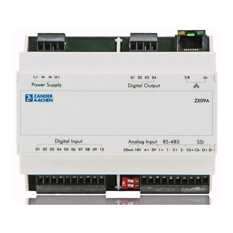
Zander Aachen ZX09 Series User manual

Operating Manual
FPGA-based High-Speed Industrial PLC
ZX09-Series
ZX20/ZX21-Series

H. ZANDER GmbH & Co. KG • Am Gut Wolf 15 • 52070 Aachen • Germany • Tel +49 241 9105010
Fax +49 241 91050138 • info@zander-aachen.de • www.zander-aachen.de
2
Operating manual ZX09/20/21-Series
Zander GmbH & Co. KG
Am Gut Wolf 15
52070 Aachen, Germany
info@zander-aachen.de
www.zander-aachen.de
Item no.: E61-436-00
Version: M06
This document is the English translation.
Technical Changes reserved,
all information is subject to change.

H. ZANDER GmbH & Co. KG • Am Gut Wolf 15 • 52070 Aachen • Germany • Tel +49 241 9105010
Fax +49 241 91050138 • info@zander-aachen.de • www.zander-aachen.de 3
Operating manual ZX09/20/21-Series
1. About this document ................................................................................. 6
1.1 Validity ........................................................................................................ 6
1.2 Target group................................................................................................ 6
1.3 Explanation of symbols ............................................................................... 6
2. General safety instructions........................................................................ 7
3. About this device ........................................................................................ 8
3.1 Product information ..................................................................................... 8
3.2 Delivery content and supplies ..................................................................... 9
3.3 Intended usage ........................................................................................... 10
3.4 Exclusion of liability and warranty ............................................................... 10
3.5 Function....................................................................................................... 10
3.6 Device diagram ........................................................................................... 11
3.6.1 ZX09 ......................................................................................................... 11
3.6.2 ZX09A ...................................................................................................... 11
3.6.3 ZX09B / ZX09C / ZX09D / ZX09E ........................................................... 12
3.6.4 ZX20T / ZX21T......................................................................................... 12
3.6.5 ZX20T/TP/TC, ZX21T/TP/TC................................................................... 13
4. Assembly ..................................................................................................... 13
4.1 Assembly on the mounting rail .................................................................... 13
4.2 Disassembly off the mounting rail ............................................................... 14
5. Electrical connection .................................................................................. 15
5.1 General rules for the electrical connection ................................................. 15
5.2 Connection terminals .................................................................................. 16
5.2.1 ZX09 / ZX09A / ZX09B / ZX09C / ZX09D / ZX09E.................................. 16
5.2.2 ZX20T/TP/TC, ZX21T/TP/TC................................................................... 18
5.3 Failure safety............................................................................................... 19
5.4 Electrical connection of the device.............................................................. 19
5.5 Inputs........................................................................................................... 20
5.5.1 Digital Inputs............................................................................................. 21
5.5.2 Connection of the digital Inputs................................................................ 22
5.5.3 Analog Inputs (only ZX09A/B/C/D/E)....................................................... 25
5.5.4 Connection of the analog inputs .............................................................. 26

H. ZANDER GmbH & Co. KG • Am Gut Wolf 15 • 52070 Aachen • Germany • Tel +49 241 9105010
Fax +49 241 91050138 • info@zander-aachen.de • www.zander-aachen.de
4
Operating manual ZX09/20/21-Series
5.5.5 The SSI-Interface (only ZX09A, ZX09D and ZX09E) .............................. 27
5.5.6 Connection of an Encoder to the SSI-Interface ....................................... 28
5.5.7 TTL differential signal inputs (only ZX09A, ZX09D, ZX09E) ................... 29
5.5.8 TTL differential signal outputs (only ZX09A, ZX09D, ZX09E) ................. 29
5.5.9 Connection of the In-/Outputs for the TTL differential signals ................. 29
5.6. Digital outputs............................................................................................. 30
5.6.1 Connection of the digital outputs.............................................................. 31
6. Programming ............................................................................................... 33
7. Networking................................................................................................... 34
7.1 Networking via Ethernet .............................................................................. 34
7.1.1 Modbus/TCP ............................................................................................ 34
7.1.2 ZanderNet ................................................................................................ 36
7.2 The RS 485-Interface (only ZX09A, ZX09D and ZX09E) ........................... 38
7.2.1 Modbus RTU ............................................................................................ 38
7.2.2 Modbus RTU wiring.................................................................................. 39
7.2.3 ZanderLink ............................................................................................... 40
7.2.4 ZanderLink wiring..................................................................................... 41
7.3 Networking via Profinet (only ZX20TP, ZX21TP) ....................................... 42
7.4 Networking via EtherCAT (only ZX20TC, ZX21TC) ................................... 43
8. Commissioning ........................................................................................... 44
8.1 What happens at the start? ......................................................................... 44
8.2 Initial commissioning ................................................................................... 45
8.2.1 Step 1: Program creation in EX_PRESS 5 .............................................. 45
8.2.2 Step 2: Connecting the power supply ...................................................... 45
8.2.3 Step 3: Programming the PLC ................................................................. 45
8.2.4 Step 4: Connecting the inputs .................................................................. 45
8.2.5 Step 5: Connecting the encoder (ZX09A, ZX09D, ZX09E) ..................... 46
8.2.6 Step 6: Controlling the function of the PLC via the LEDs ........................ 46
8.2.7 Step 7: Connection to a network.............................................................. 46
8.2.8 Step 8: Connecting the outputs................................................................ 47
8.2.9 Step 9: Connecting the power supply of the digital outputs .................... 47
9. Diagnosis ..................................................................................................... 47

H. ZANDER GmbH & Co. KG • Am Gut Wolf 15 • 52070 Aachen • Germany • Tel +49 241 9105010
Fax +49 241 91050138 • info@zander-aachen.de • www.zander-aachen.de 5
Operating manual ZX09/20/21-Series
10. Maintenance, repair and replacement .................................................... 51
11. Dimensional drawing ................................................................................ 52
12. Technical data ........................................................................................... 53
12.1 ZX09 / ZX09A............................................................................................ 53
12.2 ZX09B / ZX09C / ZX09D / ZX09E............................................................. 55
12.3 ZX20T/TP/TC, ZX21T/TP/TC.................................................................... 57
12.4 FPGA logic capacities ............................................................................... 58
13. Example 1................................................................................................... 59
13.1 The process............................................................................................... 59
13.2 Step 1: Program creation in EX_PRESS 5 ............................................... 60
13.3 Step 2: Connecting the power supply ....................................................... 64
13.4 Step 3: Programming the PLC .................................................................. 64
13.5 Step 4: Connecting the inputs ................................................................... 64
13.6 Step 6: Controlling the function of the PLC via the LEDs ......................... 65
13.7 Step 8: Connecting the digital outputs ...................................................... 65
13.8 Step 9: Connecting the power supply of the digital outputs ..................... 66
14. Example 2................................................................................................... 67
14.1 The process............................................................................................... 67
14.2 Step 1: Program creation in EX_PRESS 5 ............................................... 68
14.3 Step 2: Connecting the power supply ....................................................... 71
14.4 Step 3: Programming the PLC .................................................................. 71
14.5 Step 4: Connecting the inputs ................................................................... 71
14.6 Step 6: Controlling the function of the PLC via the LEDs ......................... 72
14.7 Step 8: Connecting the digital outputs ...................................................... 72
14.8 Step 9: Connecting the power supply of the digital outputs ..................... 73
15. Declaration of conformity ........................................................................ 74
16. Service ....................................................................................................... 75

H. ZANDER GmbH & Co. KG • Am Gut Wolf 15 • 52070 Aachen • Germany • Tel +49 241 9105010
Fax +49 241 91050138 • info@zander-aachen.de • www.zander-aachen.de
6
Operating manual ZX09/20/21-Series
1. About this Document
1.1 Validity
This document ist valid for the programmable logic controllers
ZX09 (Item-no.: 589200), ZX09A (Item-no.: 589201), ZX09B (Item-no.: 589202),
ZX09C (Item-no.: 589203), ZX09D (Item-no.: 589204), ZX09E (Item-no.: 589205),
ZX20T (Item-no.: 589000), ZX20TP (Item-no.: 589002), ZX20TC (Item-no.: 589003),
ZX21T (Item-no.: 589051), ZX21TP (Item-no.: 589052), ZX21TC (Item-no.: 589053).
1.2 Target group
This document is intended for electricians, installation-, commissioning– and service
personnel with appropriate knowledge in handling automation technology components.
1.3 Explanation of symbols
Symbol / Illustration Meaning
Document in printed form
Document is available to download at
www.zander-aachen.de
Document on USB memory stick
Safety instruction
Warning: Possible dangers
Caution: Possibility of damage to life and property
Important information
HINT Tip / useful information

H. ZANDER GmbH & Co. KG • Am Gut Wolf 15 • 52070 Aachen • Germany • Tel +49 241 9105010
Fax +49 241 91050138 • info@zander-aachen.de • www.zander-aachen.de 7
Operating manual ZX09/20/21-Series
2. General safety instructions
Only authorised and qualified personnel may install the device and
put it into operation, i.e. personnel which
- is well-acquainted with correct technical handling of the
electrical machine equipment,
- is familiar with the applicable regulations concerning occu-
pational safety and accident prevention,
- has read and understood the operating manual and, if
applicable, the programming manual
In case of incorrect connection or inappropriate use, the safe func-
tioning of the device during the machine operation will no longer be
guaranteed. This can result in fatal injuries or serious material loss.
Please observe the national guidelines, which are valid for the com-
missioning of the device.
The electrical connection of the device must take place only when
the voltage supply is switched off. This also applies to the connected
sensors and actuators.
The wiring of the device must be done in conformance with the
instructions given in this operating manual.
The person, who installs the device and puts it into operation, must
be adequately protected against electrostatic charge (earthing strap
or ESD shoes along with ESD flooring).
Opening of the device and any manipulations to the device are not
allowed; and shall result in loss of warranty and warranty claims.
Please observe all the relevant safety guidelines and standards.
Non-observance of the safety guidelines may lead to death, severe
injuries and serious material damage.
Please read the operating manual before use and preserve it care-
fully.
Please ensure that the operating manual is always available at the
time of assembly, commissioning and maintenance work.

H. ZANDER GmbH & Co. KG • Am Gut Wolf 15 • 52070 Aachen • Germany • Tel +49 241 9105010
Fax +49 241 91050138 • info@zander-aachen.de • www.zander-aachen.de
8
Operating manual ZX09/20/21-Series
3. About this device
3.1 Product information
The ZX09– and ZX20/21-series are high-speed industrial programmable logic control-
lers (PLCs). They can be used as stand-alone PLCs or in a network as decentralized
PLCs for parallel processing of signals in real time. This is made possible by the heart
of every ZX-control: A Field Programmable Gate Array (FPGA). This enables the
fastest possible and equally fast, reproducible processes without cycle time in absolute
parallelism.
The following table lists the type and number of inputs, outputs and communication
interfaces for all device types:
The programming is carried out via the programming software EX_PRESS 5
(Item.-no.: 589092 ) in structured text (ST) after IEC 61131-3.
ZX09 ZX09A ZX09B ZX09C ZX09D ZX09E ZX20T
ZX21T
ZX20TC
ZX21TC
ZX20TP
ZX21TP
Digital inputs 10 10 222220 20 20
Digital outputs 44444416 16 16
Analog inputs
0..10V/4..20mA switchable - 12222- - -
Analog-inputs 0..10V - - 4- 4- - - -
Analog-inputs 4..20mA - - - 4- 4- - -
SSI (or second RS-485) - 1- - 11- - -
RS-485 (or second SSI) - 1- - 11- - -
ZanderLink - 2- - 22- - -
TTL differential
inputs/outputs - 4- - 44- - -
Ethernet
(Modbus/TCP, ZanderNet) 111111111
PROFINET - - - - - - - - 2
(Switch)
EtherCAT - - - - - - - 2
(In/Out) -

H. ZANDER GmbH & Co. KG • Am Gut Wolf 15 • 52070 Aachen • Germany • Tel +49 241 9105010
Fax +49 241 91050138 • info@zander-aachen.de • www.zander-aachen.de 9
Operating manual ZX09/20/21-Series
3.2 Delivery content and supplies
Delivery content
High-Speed-PLC ZX09 (Item.-no.: 589200), ZX09A (Item-no.: 589201),
ZX09B (Item-no.: 589202), ZX09C (Item.-no.: 589203), ZX09D (Item.-no.: 589204),
ZX09E (Item.-no.: 589205) or ZX20T (Item.-no.: 589000),
ZX20TP (Item.-no.: 589002), ZX20TC (Item.-no.: 589003),
ZX21T (Item.-no.: 589051), ZX21TP (Item.-no.: 589052)
or ZX21TC (Item.-no.: 589053)
Pluggable screw terminals (plugged into the device when delivered):
ZX09: 1 x 10-pin and 2 x 4-pin
ZX09A: 2 x 10-pin and 2 x 4-pin
ZX09B/C: 1 x 10-pin and 3 x 4-pin
ZX09D/E: 1 x 10-pin and 5 x 4-pin
ZX20T/TP/ZC, ZX21T/TP/TC: 4 x 10-pin
This operating manual
Required supplies
Designation Execution Item-no.:
EX_PRESS 5 USB memory stick 589092
Note!
For the program creation and programming of the High-Speed-PLC
you need the software package EX_PRESS 5 in the latest version,
which is separately available.
Designation Item-no.:
Set of plug terminals with cable exits for ZX09 on the side 589270
Set of plug terminals with cable exits for ZX09A on the side 589271
Set of plug terminals with cable exits for ZX09B/C on the side 589272
Set of plug terminals with cable exits for ZX09D/E on the side 589273
Set of plug terminals with cable exits for ZX20/ZX21 on the side 589070

H. ZANDER GmbH & Co. KG • Am Gut Wolf 15 • 52070 Aachen • Germany • Tel +49 241 9105010
Fax +49 241 91050138 • info@zander-aachen.de • www.zander-aachen.de
10
Operating manual ZX09/20/21-Series
3.3 Intended usage
The ZX09- und ZX20/21-Series have been designed for the use in machines and
plants for industrial use. They must be installed in switch cabinets or appropriate hous-
ings with minimum degree of protection IP54. The approved operating parameters for
use must be complied with (see chapter 12 “Technical data”).
The inputs and outputs have to be connected accordingly.
The controls can be integrated as slaves into an existing Modbus TCP/IP network or
build an existing network with the Multimaster protocol “ZanderNet“ via the
Ethernet-interface.
The controllers ZX20TP and ZX21TP can be integrated as slave (PROFINET IO-
Device) into a PROFINET-network. The controls ZX20TC and ZX21TC can be ad-
dressed as slave in an EtherCat-network.
3.4 Exclusion of liability and warranty
If the conditions above are not complied for the intended use, the safety instructions
are not followed, or maintenance work is not performed as required, it will lead to a
disclaimer or loss of warranty.
3.5 Function
The function of the device depends upon the loaded user program. The logic stored in
this program determines how the input signals are evaluated and the outputs switch.
Note!
The user is responsible for the integration of the device into the overall
system. For this, the correct electrical installation and the correct pro-
gramming of the ZX09, ZX09A, ZX09B, ZX09C, ZX09D, ZX09E,
ZX20T/TP/TC or ZX21T/TP/TC must be verified.

H. ZANDER GmbH & Co. KG • Am Gut Wolf 15 • 52070 Aachen • Germany • Tel +49 241 9105010
Fax +49 241 91050138 • info@zander-aachen.de • www.zander-aachen.de 11
Operating manual ZX09/20/21-Series
3.6 Device diagram
3.6.1 ZX09
3.6.2 ZX09A
Power FPGA Controller
ZX09
Digital Outputs
Digital Inputs
Ethernet
02 0301U+
L+ MM04
02 0301 04 06 0705 08 1009
Power Supply
Fig. 1: Device diagram ZX09
Fig. 2: Device diagram ZX09A
Power FPGA Controller
ZX09A
Digital Outputs
Digital Inputs
Ethernet
02 0301U+
L+ MM04
02 0301 04 06 0705 08 1009 1+ 1- 2- CK+
2+ CK-
Power Supply
DT+ DT-
RS-422/485 SSI
0VA+
Analog to
Digital
Converter
Analog
Inputs

H. ZANDER GmbH & Co. KG • Am Gut Wolf 15 • 52070 Aachen • Germany • Tel +49 241 9105010
Fax +49 241 91050138 • info@zander-aachen.de • www.zander-aachen.de
12
Operating manual ZX09/20/21-Series
3.6.3 ZX09B / ZX09C / ZX09D / ZX09E
3.6.4 ZX20T / ZX21T
Power FPGA Controller
ZX09B/C/D/E
Digital Outputs
Digital
Inputs
Ethernet
02 0301U+
L+ MM04
0201
Power Supply
0VA5+
Switchable
Analog Inputs
A1+ 0V A2+ 0V A3+ 0V A4+ 0V 0VA6+
A/D
Conv.
A/D
Conv.
A/D
Conv.
A/D
Conv.
A/D
Conv.
Non - switchable
Analog Inputs
A/D
Conv.
CK+ CK- DT+
SSI
DT-
2-2+
1-
RS-485
1+
RS-485/SSI:
Only ZX09D/E
Fig. 3: Device diagram ZX09B / ZX09C / ZX09D / ZX09E
Fig. 4: Device diagram ZX20T / ZX21T
Power FPGA Controller
ZX20T
Digital Outputs
Digital Inputs
Ethernet
02 0301U+
L+ MM04 06 0705 08 10 1109 12 14 1513 16
02 0301 04 06 0705 08 10 1109 12 14 1513 16 18 1917 20
Power Supply
ZX20T
ZX21T

H. ZANDER GmbH & Co. KG • Am Gut Wolf 15 • 52070 Aachen • Germany • Tel +49 241 9105010
Fax +49 241 91050138 • info@zander-aachen.de • www.zander-aachen.de 13
Operating manual ZX09/20/21-Series
3.6.5 ZX20TP / ZX20TC / ZX21TP / ZX21TC
4. Assembly
Please note:
The device must be installed in a switch cabinet or suitable housing with a minimum
degree of protection of IP54
Mount the controller on a 35 mm mounting rail according to EN 60715
Maintain a mounting distance of minimum 5 mm from the adjacent devices
Ensure that there is sufficient heat dissipation in the switch cabinet.
Keep the PLC away from devices or components, which carry high voltage or cause
strong electrical interference.
4.1 Assembly on the support rail
The black underside of the device is placed flat on the mounting rail (see Fig. 6). Then
press the unit firmly onto the mounting rail with your palms (see Fig. 7) until both or-
ange locking slides, which are located at the bottom, in the middle, on the long outer
sides and on the underside of the control unit, are engaged.
Fig. 5: Device diagram ZX20TP / ZX20TC / ZX21TP / ZX21TC
ZX20TP
ZX20TC
ZX21TP
ZX21TC

H. ZANDER GmbH & Co. KG • Am Gut Wolf 15 • 52070 Aachen • Germany • Tel +49 241 9105010
Fax +49 241 91050138 • info@zander-aachen.de • www.zander-aachen.de
14
Operating manual ZX09/20/21-Series
4.2 Disassembly off the mounting rail
The two orange locking slides (top and bottom) are pulled out one after the other with
a screwdriver (blade width max. 3.5 mm) (see Fig. 8). The device is then released
from the top-hat rail and can be removed.
Fig. 8. Pull the catch to the outside
Fig. 6: Place device on top hat rail Fig. 7: Press device onto top-hat rail

H. ZANDER GmbH & Co. KG • Am Gut Wolf 15 • 52070 Aachen • Germany • Tel +49 241 9105010
Fax +49 241 91050138 • info@zander-aachen.de • www.zander-aachen.de 15
Operating manual ZX09/20/21-Series
5. Electrical connection
5.1 General rules for the electrical connection
Please also note:
All electrical connections must be isolated from the mains either by safety transform-
ers (SELV/PELV) according to IEC 61558-2-6 with limitation of the output voltage in
the event of a fault or by equivalent isolation measures.
All outputs must have sufficient protective circuits for inductive loads. For this
purpose, the outputs must be protected with freewheeling diodes or varistors.
Do not lay the signal and communication lines of the digital inputs in the same cable
tray as AC supply voltage lines or lines with high interference levels. Keep a mini-
mum distance of 20 cm to such cable trays.
It is recommended to use shielded network cables of category Cat. 7 for the network
connection.
For connection to the SSI or RS 485 interface (ZX09 series only) a shielded, twisted
pair cable is required (see Fig. 15).
Tighten the screws of the connection terminals to a maximum of 0.8 Nm.
Warning
The operating voltage (DC 24V) must correspond to the specifications
given in chapter 12 "Technical data".
The voltages at the digital inputs must correspond to the specifications
given in chapter 12 "Technical Data".
The voltages and currents at the analog input must correspond to the
specification given in chapter 12 "Technical Data".
The voltage applied to the voltage input of the digital outputs ("U+")
must correspond to the specifications given in chapter 12 "Technical
Data".
Do not connect external voltage to the digital outputs.
The supply voltage must be switched off during wiring. The supply
voltages of all sensors and actuators must also be switched off.
Non-observance of these instructions can result in the destruction of
electronic components within the device! In this case, warranty or
guarantee claims are excluded.

H. ZANDER GmbH & Co. KG • Am Gut Wolf 15 • 52070 Aachen • Germany • Tel +49 241 9105010
Fax +49 241 91050138 • info@zander-aachen.de • www.zander-aachen.de
16
Operating manual ZX09/20/21-Series
5.2 Connection terminals
5.2.1 ZX09 / ZX09A / ZX09B / ZX09C / ZX09D / ZX09E
Terminal Description
L+ Positive supply voltage UB
M (2 equivalent terminals) Connection 0 V of the supply voltage and the
voltage for the digital outputs and 0 V potential
for digital and analog inputs.
M and 0V are connected internally
U+ Connection for the positive voltage switched by
the digital outputs (can be different from operat-
ing voltage L+)
Digital Input 01..02
01..10
Digital inputs
Digital Output 01..04 Digital outputs
Analog Input A+ / 0V
A1+ / 0V ... A6+ / 0V
Analog current or voltage inputs
Ethernet interface
RS-485 Serial interface RS-485/422 or second SSI
interface (only ZX09A, ZX09D, ZX09E)
SSI SSI interface or second RS-485 interface (only
ZX09A, ZX09D, ZX09E)

H. ZANDER GmbH & Co. KG • Am Gut Wolf 15 • 52070 Aachen • Germany • Tel +49 241 9105010
Fax +49 241 91050138 • info@zander-aachen.de • www.zander-aachen.de 17
Operating manual ZX09/20/21-Series
ZX09A
Digital Output
01 02 03 04 T/R Lk
Digital Input
01 02 03 04 05 06 07 08 09 10 1+ 1-2+ 2-Ck+ Ck- D+ D-
RS-485 SSI
Analog Input
20mA 10V A+ 0 V
RUN OC 1 2 3
Fig. 9: Connection terminals ZX09A
Fig. 10: Connection terminals ZX09B / ZX09C / ZX09D / ZX09E
U+
Power Supply
L+ MM
Digital Output
01 02 03 04 T/R Lk
Digital Input
01 02 A1+0V A2+0V A3+0V A4+0V
Switchable Analog Input
10 V
A5+0V
RUN OC 1234
Analog Input
A6+0V
20 mA
10 V
20 mA
Only ZX09D/E
SSI
Ck+ Ck– D+ D-
2- 2+ 1- 1+
RS-485
Only ZX09D/E
ZX09B/C/D/E
Power Supply
L+ MMU+

H. ZANDER GmbH & Co. KG • Am Gut Wolf 15 • 52070 Aachen • Germany • Tel +49 241 9105010
Fax +49 241 91050138 • info@zander-aachen.de • www.zander-aachen.de
18
Operating manual ZX09/20/21-Series
5.2.2 ZX20T/TP/TC, ZX21T/TP/TC
Terminal Description
L+ Positive supply voltage UB
M (2 equivalent terminals) 0 V - Connection of the supply voltage and the
voltage for the digital outputs and 0 V potential for
digital inputs. M and 0 V are internally connected
U+ Positive voltage for the dig. outputs
(can be different to operating voltage L+)
Digital Input 01..20 Digital inputs
Digital Output 01..16 Digital inputs
Ethernet-interface
PROFINET IO-Device PROFINET-interface (only ZX20TP, ZX21TP)
EtherCAT Slave EtherCAT-interface (only ZX20TC, ZX21TC)
Fig. 11: Connection terminals ZX20T/TP/TC, ZX21T/TP/TC
108
ZX20T/TP/TC
ZX21T/TP/TC
BF / ERR
SF / RUN
SYS
Digital Input
01 02 03 04 05 06 07 08 09 10 11 12 13 14 15 16 17 18 19 20
U+
Power
L+ MM
Digital Output
01 02 03 04 05 06 07 08 09 10 11 12 13 14 15 16
PROFINET IO-Device
EtherCAT Slave
RX/TX RX/TX
Link Link
IN OUT
L/A L/A
Pwr
Digital Output
Digital Input

H. ZANDER GmbH & Co. KG • Am Gut Wolf 15 • 52070 Aachen • Germany • Tel +49 241 9105010
Fax +49 241 91050138 • info@zander-aachen.de • www.zander-aachen.de 19
Operating manual ZX09/20/21-Series
5.3 Failure safety
The operating voltage L+ / M is reverse polarity protected.
All digital outputs are short-circuit proof.
5.4 Electrical connection of the device
The electrical connection of the device is shown in Figs. 12 and 13. The power supply
is connected to the instrument via terminals L+ and M on the upper left terminal block.
The max. permissible voltage on the mentioned terminal is approx. 27.5 V
( 24 V + 15%, see chapter 12 "Technical data"). For wiring, the positive voltage must
be connected to terminal L+ and the corresponding 0 V potential to M. The PE poten-
tial of the voltage source must be grounded according to the requirements of the
system. The controller itself must not be additionally earthed.
Warning:
The switching capacity and the switching capacity of the power supply unit
specified in chapter 12 "Technical data" must be observed.
information for the digital outputs must be observed. In case of overload
the output drivers can be destroyed.
Warning:
Do not connect terminal M to the PE connection of the voltage source, as
this can lead to massive EMC interference.
Fig. 12: Connection of the power supply of the ZX09/A/B/C/D/E
U+
Power Supply
L+ MM
RUN
24 V
0 V

H. ZANDER GmbH & Co. KG • Am Gut Wolf 15 • 52070 Aachen • Germany • Tel +49 241 9105010
Fax +49 241 91050138 • info@zander-aachen.de • www.zander-aachen.de
20
Operating manual ZX09/20/21-Series
5.5 Inputs
All device variants have digital inputs, and the ZX09A, ZX09B, ZX09C, ZX09D and
ZX09E variants also have analog inputs. These can be connected to the desired
sensor system via the lower terminal blocks "Digital Input" or "Analog Input".
If an input signal is applied to one of the inputs of a ZX20/21 series controller, this is
indicated by a green LED on the PLC (see Figs. 14A and 14B). The LEDs "01", "02",
"03", ... , "20" are continuously assigned to the digital inputs "01", "02", "03", ... , "20".
The ZX09 series do not have LEDs to indicate the input states.
108
Fig. 13: Connection of the power supply of the ZX20T/TP/TC, ZX21T/TP/TC
U+
Power
L+ MM
24 V
0 V
Note:
In the "Structured Text", input variables for digital inputs can be assigned
to the above-mentioned connection terminals via the keyword "AT" using
the designations "In_01", "In_02", ... , "In_10". Detailed information on this
can be found in the programming manual in Chapter 2.2.5.1
"VAR_INPUT / VAR_OUTPUT", which is included as a PDF file in the
software package "EX_PRESS 5" (Art. No. 589092) on the USB stick
included in the package.
Other manuals for ZX09 Series
2
This manual suits for next models
26
Table of contents
Other Zander Aachen Controllers manuals