13GB
○○○○○○○○○○○○○○○○○○○○○○○○○○○○○○○○○○○○○○○
○○○○○○○○○○○○○○○○○○○○○○○○○○○○○○○○○○○○○○○○○○○○○○○
• Splashba k (optional)
When a splashback is to be fitted, the distance between the
hood and the cooking appliances will be determined by the height
of the splashback B and whether or not there is a raised back
on the worktop. The splashback is to be installed before installing
the canopy. If the splashback is to be fixed to the wall sing
both the top and bottom fixing holes, care m st be taken to
ens re that the splashback is fitted at the correct height before
fixing the base nits or at least the worktop covering them. As
this is a complex operation, it sho ld only be ndertaken by the
technician installing the kitchen nits or by a competent person
who knows the final dimensions of the nits. If the splashback
is to be fixed thro gh the top fixing holes only, proceed as follows:
a) Rest the splashback on the worktop and against the wall, as
ill strated in fig. 2.
b) Mark the centres of the two holes in the top s rface.
c) Drill the wall sing an 8 mm drill bit, and fix the splashback
sing the rawl pl gs and screws provided.
d) If necessary, the installer sho ld sec re the splashback to
the wall by t cking the bottom edge down behind the rear of
the worktop.
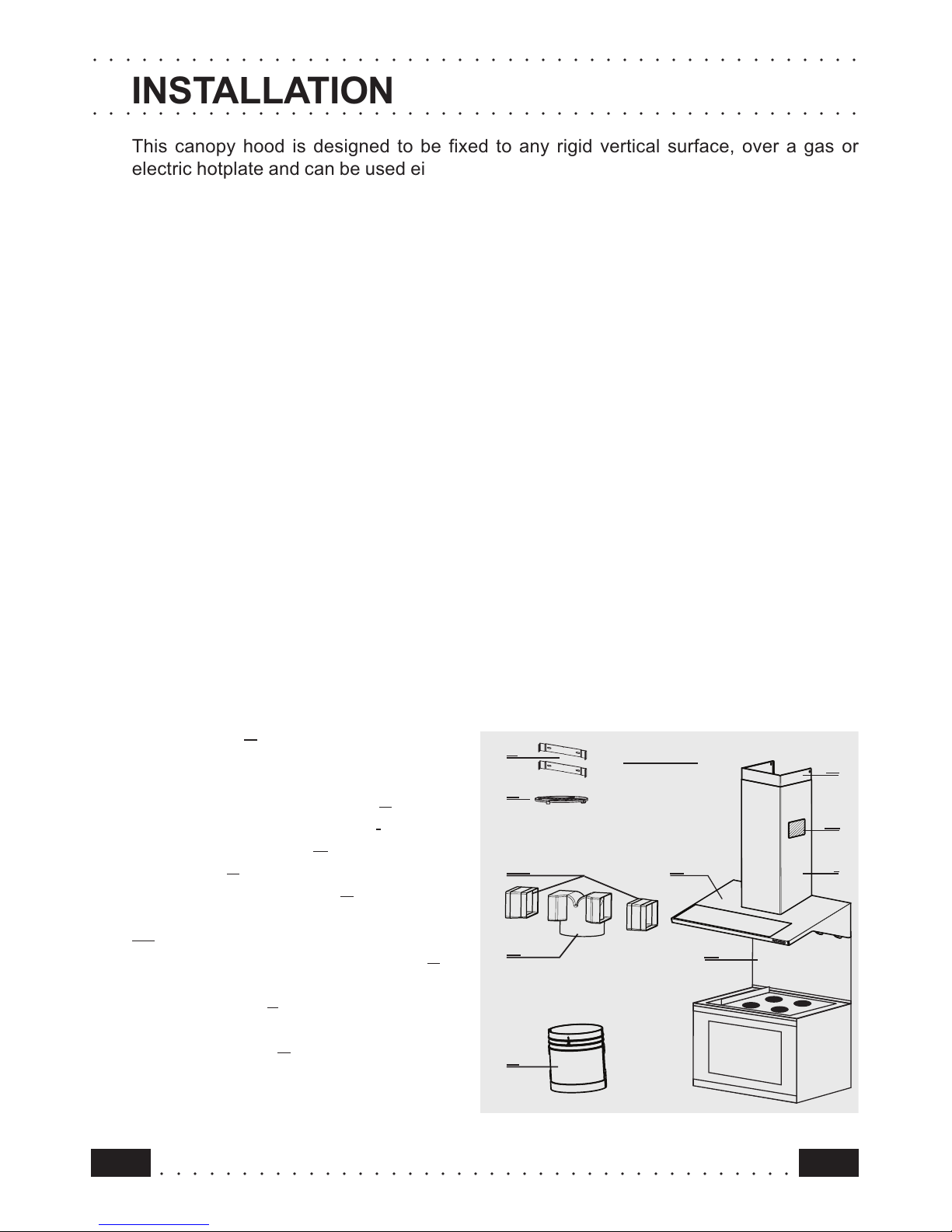
Fixing the anopy
Before starting to fix the canopy it will be necessary to adj st
the s pport brackets S1 by t rning the adj stment screws in
a clockwise direction ntil their reach their limit (Fig.3):
a) Hook the canopy onto the two size 4.2 x 44.4 screws 1 fitted
as described above (Fig. 4).
b) Level the hood by t rning the adj stment screws and then
locking them.
Ele tri al onne tion and working test
• Before onne ting to the mains supply ensure that the mains
voltage orresponds with the voltage on the rating plate inside
the hood.
• Conne t the ooker hood to the mains via a double pole swit h
whi h has 3 mm learan e between the onta ts.
• The applian e must be earthed.
• On e the ele tri al onne tion has been ompleted, he k that
worktop illumination, motor and speed work properly.
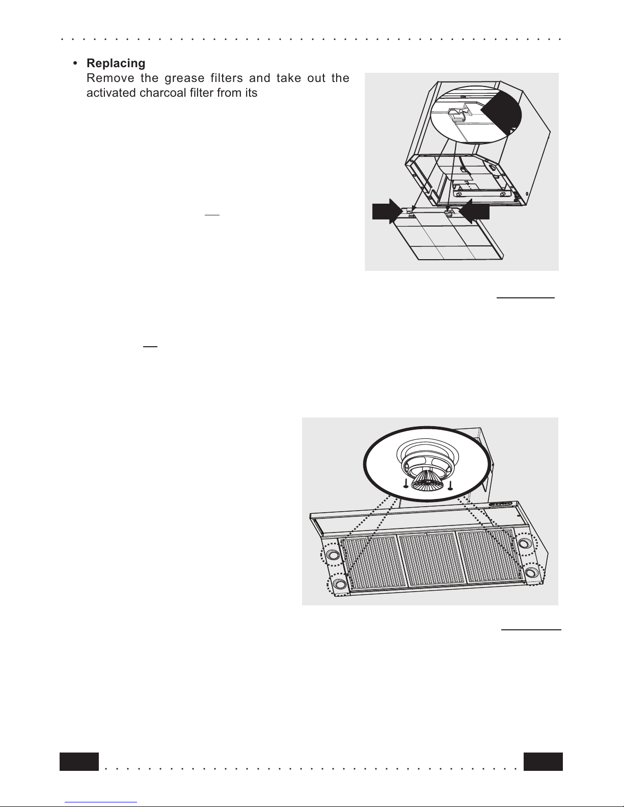
Du ting or Re ir ulation fitting
• Du ting fitting
• The hood can be d cted to the o tside sing either rigid or flexible
d cting Ø 150 mm, the choice of which is left to the installer (fig.5).
• C t the additional spigot P in correspondence with o tlets 1 and
2, which m st be formed directly on the piece. Connect the
additional spigot P to the ro nd fan o tlet, p shing it downwards,
and fit spigot R to additional spigot P in a similar manner (make
s re that the two additional side recirc lation spigots P1 are fitted
S1
S1
S1
S1