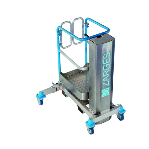
zarges Service Lift User manual

en ZARGES Service Lift with winch and gripper from Tractel
Greifzug
Daily inspection plan and record
N° TP-TG-EN

Imprint
ZARGES GmbH
Zargesstraße 7
82362 Weilheim, Germany
Tel.: +49 881 / 687-100
Fax: +49 881 / 687-500
E-mail: [email protected]
Internet: www.zarges.de
March 2016

3
Table of contents
1 About these instructions ......................................................................................................................................4
1.1 Symbols used .....................................................................................................................................................................................................4
1.2 Structure of warnings......................................................................................................................................................................................4
2 Safety ...........................................................................................................................................................................4
2.1 Personnel .............................................................................................................................................................................................................5
3 Information on the inspection record .............................................................................................................5
4 Procedure for triggering the gripper................................................................................................................6
5 Fitting seals ...............................................................................................................................................................6
5.1 Seal on the winch..............................................................................................................................................................................................6
5.2 Control box sealing ..........................................................................................................................................................................................6
6 Attaching inspection stickers..............................................................................................................................7
7 General inspection steps ......................................................................................................................................7
7.1 Checking sealing...............................................................................................................................................................................................7
7.2 Inspecting inspection stickers......................................................................................................................................................................7
8 Inspection steps for components......................................................................................................................8
8.1 Equipment overview .......................................................................................................................................................................................8
8.2 Inspecting the gripper for functionality...................................................................................................................................................8
8.3 Checking the brakes of the winch and centrifugal force weight of the gripper........................................................................9
9 What to do in case of emergency lowering................................................................................................ 11

4
About these instructions
1 About these instructions
This inspection plan is used for the regular checking of the service lift and is only valid in conjunction with the
original operating instructions. It must be included with every service lift.
Service lifts with Tractel Greifzug components (original operating instructions as old as or older than the revision
from 1 July, 2015) must be provided with this inspection plan and seals immediately and before any further use.
The inspection steps listed in this inspection plan must be carried out and recorded at least once for each day the
service lift is used. The inspection must always be carried out before the rst use of the service lift.
The operating instructions and this inspection plan must be followed precisely. Service records must be lled out
without gaps, completely and carefully. Defects must be reported to the operator and the manufacturer of the
service lift immediately. The service information (TBA6000) included with the operating instructions can be used
for this purpose.
Each emergency lowering (see original operating instructions for denition) must be documented specically in
the inspection plan and reported to the operator and the manufacturer of the service lift. The service information
included with the operating instructions can be used for this purpose. The service lift must be decommissioned
until it has been examined by qualied and trained personnel.
The inspection stickers supplied with this document must be provided with the date of the initial commissioning,
the date of the most recent servicing by qualied and trained personnel and the date of the last inspection by
an expert, all in accordance with the documentation. The inspection stickers must be lled out at the intended
location at the service lift before the lift is operated.
The seals (item number 61875) supplied with this document must be tted by a person qualied by the operator
and trained by ZARGES in accordance with the instructions in this inspection plan.
1.1 Symbols used
Symbol Meaning
"Important information"
Information on preventing property damage, fostering understanding or optimising work ows
XSymbol for an action.
XIf there are multiple steps with actions, follow them in the order presented.
1.2 Structure of warnings
SIGNAL WORD
Type, source and consequence of the danger
fMeasures for preventing the danger.
2 Safety
If the gripper and winch are not inspected properly, there is a risk of serious injury or death due to falling!
The gripper and winch of the service lift must be fully functional. To ascertain their functionality, all the inspection
steps listed in this inspection plan must be carried out and recorded on a daily basis before the rst use of the
service lift.
If one of the inspections fails, the service lift must be decommissioned immediately.
A corresponding sign must be attached at the main switch of the service lift.
Inspection steps to be carried out:
àChapter 7 “General inspection steps”on Page7
àChapter 8 “Inspection steps for components”on Page8
If the gripper and winch are not serviced properly, there is a risk of serious injury or death due to falling!

5
Information on the inspection record
Contrary to any deviating inspection intervals of the manufacturer's operating instructions for the winch and
gripper, they must be serviced and inspected annually by a qualied person who has been trained in this activity
in accordance with the instructions from the manufacturer. Should service not have been performed for more
than a year, it must be carried out immediately in accordance with the specications of the manufacturer before
the service lift may be used. During annual service, the drive and pressure rollers of the gripper (Tractel Greifzug)
are also to be replaced with factory-new rollers impressed with the date of manufacture.
Winches and grippers must undergo a general overhaul by the manufacturer or a specialist company authorised
by the manufacturer in accordance with the manufacturer's specications, however no later than after 10 years or
250 operating hours (whichever comes rst).
Should anything unusual be observed with regard to winches or grippers (e.g. strange noises, deformations etc.),
the service lift must be decommissioned immediately and without further movement. The components must be
examined immediately by qualied personnel who are trained in these activities from the component manufac-
turer.
2.1 Personnel
The inspection steps of this inspection plan may only be carried out by a qualied service lift operator and in the
presence of another qualied person (for further information, see original operating instructions).
The persons at the wind power station (WPS) must be able to make an emergency call at any time.
The service, maintenance and initial commissioning of the service lift and other work on the service lift may only
be carried out by personnel who have been trained by ZARGES and qualied for these activities. Work on winches
and grippers may only be carried out by personnel who have received the relevant training by the manufacturer.
Service and maintenance of the winch and gripper may only be carried out by the component manufacturer
themselves or by trained personnel authorised by the component manufacturer.
A general overhaul may only be carried out by the component manufacturer themselves or by personnel author-
ised by them (see original operating instructions and manufacturer's operating instructions for the winch and
gripper).
A ZARGES service lift may only be operated by personnel who have been instructed in proper operation and be-
haviour in case of emergency as part of their operator training. The participation of qualied and trained opera-
tors in such training must be conrmed with a certicate. The certicate must be renewed every 2 years.
3 Information on the inspection record
The results of the inspection steps must be documented in the inspection record. The inspection record is located
in the Appendix of this document.
XEnter the WPS number, service lift serial number, gripper type and winch type in the intended eld of the
inspection record.
XEnter the date of the inspection.
XTick the "Seals" and "Stickers" elds to conrm that they have been inspected and tick all inspections under
"Gripper" and "Winch" to conrm that they have been carried out.
XIf an inspection has failed and a component is not functional, tick the "Out of service" eld.
XIf all inspections have been completed successfully and all components are functional, tick the "Ready for
operation" eld.
XTick the "Catch" eld if a catch has occurred.
XTick the "Emergency lowering" eld if emergency lowering has occurred.
XEnter the company and name of the inspector in block letters.
XEnter the signature of the inspector.
XEnter any special items of note in the "Notes" eld.

6
Procedure for triggering the gripper
4 Procedure for triggering the gripper
The gripper may be triggered, in particular with higher towers (hub height over 80 m), if:
àLift movement due to the elasticity of the suspension cable while starting or stopping (stop-and-go move-
ment) is incorrectly detected at the safety cable as lift movement at an excessive speed.
In this case, the gripper can be recommissioned. For this purpose:
XOpen the gripper manually or through a short upward movement using the hand crank and the brake venting
lever.
XDocument the catch in the inspection plan.
If an upward movement is not possible (e.g. due to suspension device breakage, lack of traction, damaged sus-
pension cable or similar malfunction causes) or if the gripper is triggered again:
XSend the gripper to the manufacturer to be examined in accordance with the specications of the manufactur-
er (see original operating instructions of the service lift and gripper).
XDo not commission the service lift again until the cause of the fault has been veriably eliminated.
XTick the "Catch" eld in the inspection plan, document it separately and inform the operator and manufacturer
of the service lift.
5 Fitting seals
5.1 Seal on the winch
XClean the area around the opening for overload
setting with alcohol (or similar).
XFit the seal over the opening for overload setting.
5.2 Control box sealing
XClean the area with alcohol (or similar).
XFit the seal on the control box.

7
Attaching inspection stickers
6 Attaching inspection stickers
ZARGES service lifts must be provided with inspection stickers the next time
annual service is carried out, but no later than April 2017.
XHave the inspection stickers lled out according to the available documen-
tation by an expert the rst time they are attached:
àDate of initial commissioning
àDate of last servicing
àDate of last inspection
àDate of next servicing (faces upward)
XAttach the inspection stickers to the inspection sticker strip (item number
35104380000) in the intended location (see gure).
XAttach the inspection sticker strip in the intended location next to the type
plate in the service lift.
7 General inspection steps
7.1 Checking sealing
Before each use by the operating personnel, ensure that:
XThe seal over the opening for overload setting is in place and not
broken (see Chapter 5).
XThe seal at the control box is in place and not broken (see Chap-
ter 5).
If the seal is not in place or is broken:
XDecommission the service lift immediately.
XAttach a corresponding sign at the main switch of the service lift.
XHave the respective component inspected and repaired by the manufacturer or a qualied person who has
been trained in this task.
The inspections and results must be documented in the inspection record immediately after the inspection.
XTick the "Seals" eld after the inspection has been carried out.
XIf the inspection failed, tick the "Out of service" eld.
XEnter any special items of note in the "Notes" eld.
7.2 Inspecting inspection stickers
XBefore each use by the operating personnel, ensure that:
àThe date of the initial commissioning is located on the sticker.
àThe date of the next servicing is located on the sticker and has not
expired.
XObserve national regulations and, if necessary, ensure that the date of
the inspection by the expert is located on the sticker and has not expired.
In case of faults, malfunctions, damage, missing or expired inspection stick-
ers or other defects:
XDecommission the service lift immediately.
XAttach a corresponding sign at the main switch of the service lift.
XGet caught up on expired inspection by an expert immediately.
XRecord the issue separately, report it to the manufacturer and operator
and have it examined by a qualied person who has been trained by
ZARGES.
The inspections and results must be documented in the inspection record immediately after the inspection.
XTick the "Stickers" eld after the inspection has been carried out.
XIf the inspection failed, tick the "Out of service" eld.
XEnter any special items of note in the "Notes" eld.

8
Inspection steps for components
8 Inspection steps for components
8.1 Equipment overview
1 Hand lever
2 EMERGENCY STOP button
3 Viewing window
4 Centrifugal force weight
5 Plug
6 Gripper
7 Winch
8 Opening for brake venting
9 Opening for overload setting
8.2 Inspecting the gripper for functionality
Before each use of the service lift, ensure that the gripper (6) is triggered as prescribed by clamping the safety
cable.
For this purpose, carry out the following steps in order:
XVisually inspect to ensure that the gripper (6) is
properly secured to the service lift.
XSet the hand lever (1) to position A.
àThe gripper (6) is open.
XPress the EMERGENCY STOP button (2).
XEnsure that the hand lever (1) is set to position B.
XEnsure that the safety cable cannot be pulled
upward.
àThe gripper (6) is closed.
XOpen the brake of the winch using the brake
venting lever (10) until the full weight of the lift
is suspended in the gripper.
The lift must be held by the gripper.
XMove upward with the hand wheel (11) until the
gripper can be opened.
XSet the hand lever (1) to position A.
àThe gripper (6) is open.
XPull the safety cable upward with a jerk.
XEnsure that the hand lever (1) is set to position B.
XEnsure that the safety cable cannot be pulled
upward.
àThe gripper (6) is closed.
1
2
3
5
4
67
9
8
AB
B
AB
B

9
Inspection steps for components
The gripper (6) is not closing, and the safety cable can be pulled up:
XDecommission the service lift immediately.
XAttach a corresponding sign at the main switch of the service lift.
XInform the operator and manufacturer of the service lift.
XHave the gripper (6) inspected and repaired by authorised and qualied specialist personnel.
The inspections and results must be documented in the inspection record immediately after the inspection.
XTick the "Trigger" eld after the inspection has been carried out.
XIf the inspection failed, tick the "Out of service" eld.
XEnter any special items of note in the "Notes" eld.
8.3 Checking the brakes of the winch and centrifugal force weight of the gripper
DANGER!
Serious injury or death due to falling as a result of a non-functioning brake.
XPress the EMERGENCY STOP button.
XDisconnect the power supply to the winch via the main switch.
XDecommission the service lift immediately.
XAttach a corresponding sign at the main switch of the service lift.
XInform the operator and manufacturer of the service lift.
XHave the winch and gripper examined and repaired by authorised and qualied specialist personnel.
DANGER!
Risk of serious injury from falling objects.
XDo not remain under suspended loads.
XCordon o the area of danger.
Before each use of the service lift, ensure that
àThe centrifugal force weight (4) rotates during movement of the lift
àThe brake grips and holds the service lift on the suspension cable
For this purpose, carry out the following steps in order:
XVisually inspect to ensure that the winch (7) is properly
secured to the service lift.
XEnsure that the plug (5) is positioned correctly at the
motor.
XSet the hand lever (1) to position A.
àThe gripper (6) is open.
XMove the service lift up approx. 2 metres.
XLook in the viewing window to ensure that the centrifu-
gal force weight (4) rotates during lift movement.
àIn general, the centrifugal force weight (4) must be
observed through the provided viewing window
during each movement of the lift.
2.
1.
1.

10
Inspection steps for components
The centrifugal force weight (4) is not turning:
XStop lift movement immediately.
XPress the EMERGENCY STOP button (2) immediately.
àThe hand lever (1) jumps from position A to
positionB.
àThe gripper (6) closes, and lift movement stops.
XDisconnect the power supply to the winch (7) via the
main switch.
XDecommission the service lift immediately.
XAttach a corresponding sign at the main switch of the
service lift.
XInform the operator and manufacturer of the service lift.
XHave the gripper (6) inspected and repaired by
authorised and qualied specialist personnel.
XStop lift movement.
àThe brake grips and holds the service lift on the sus-
pension cable.
XMove the service lift downward.
XStop lift movement.
àThe brake grips and holds the service lift on the sus-
pension cable.
The brake does not grip and does not hold the service lift
on the suspension cable:
XPress the EMERGENCY STOP button (2) immediately.
àThe hand lever (1) jumps from position A to position
B.
àThe gripper (6) closes, and lift movement stops.
XDisconnect the power supply to the winch (7) via the
main switch.
XDecommission the service lift immediately.
XAttach a corresponding sign at the main switch of the
service lift.
XInform the operator and manufacturer of the service lift.
XHave the winch (7) inspected and repaired by authorised
and qualied specialist personnel.
The inspections and results must be documented in the inspection record immediately after the inspection.
XTick the "Drive," "Motor brake" and "Centrifugal force weight" elds after the inspection has been carried out.
XIf the inspection failed, tick the "Out of service" eld.
XIf all inspections have been completed successfully, tick the "Ready for operation" eld.
XEnter any special items of note in the "Notes" eld.
A
B
2.
1.
A
B

11
What to do in case of emergency lowering
9 What to do in case of emergency lowering
DANGER
Risk of falling!
The winch may only be lowered manually in an emergency.
XDo not carry out emergency lowering with an overload.
XAfter each emergency lowering, have the winch checked by Tractel Greifzug GmbH or a hoist
service centre authorized by Tractel Greifzug GmbH.
XReplace damaged or worn parts.
Exceptions:
àEmergency lowering from the emergency limit switch.
àEmergency lowering over a distance of less than 20cm.
WARNING
Risk of crushing.
Emergency lowering is impermissible as a substitute for electrical lowering and leads to increased
wear on the centrifugal brake and potential failure of the brake.
XObserve the path of movement carefully, as the electrical safety functions are not active.
XIt is impermissible for anyone to remain under the service lift in the area of danger or on the lad-
der.
àEmergency lowering must be interrupted for at least 5 minutes after a downward movement of approx. 30 m.
XEach movement with emergency lowering must be documented in the inspection record!
XOnce emergency lowering has been carried out, tick the "Emergency lowering" eld and the "Out of service"
eld.
XSend the winch to be checked by the manufacturer.
XInform the operator and manufacturer of the service lift.

Daily inspection record
WPS No.
Service lift serial number
Gripper type
Winch type
Date
Inspection Event
Out of
service
Company/name of the
inspector (block letters)
Signature of
inspector Notes
Seals Stickers
Gripper Winch Ready for
opera-
tion
Emer-
gency
lowering
Catch
Trigger
Centrifugal
force
weight
Drive Motor
brake

ZARGES GmbH
Zargesstraße 7
82362 Weilheim, Germany
Tel.: +49 881 / 687-100
Fax: +49 881 / 687-500
E-mail: [email protected]
Internet: www.zarges.de
March 2016
Table of contents
Other zarges Lifting System manuals
Popular Lifting System manuals by other brands

CTE
CTE ZED 20.3 HV Instructions for use and maintenance

babcopark
babcopark Starke 2127 user manual

Anthony Liftgates
Anthony Liftgates ETU-20-44 Maintenance manual

Wienold Lifte
Wienold Lifte Universal Premium Owner's/operator's manual

HALDER
HALDER 2B353.0012 Short instruction manual

Genie
Genie Lift Tools GS-2669 Operator's manual