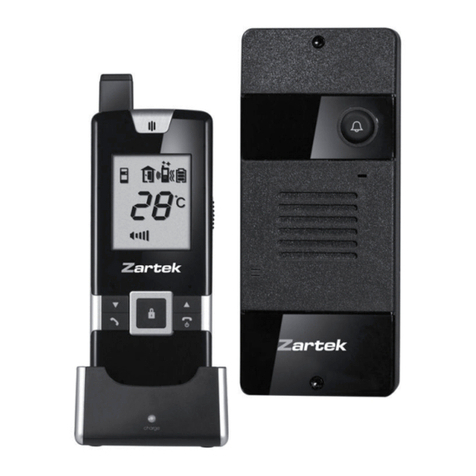
Zartek ZA-601 User manual


2
Introduction
Thank you for purchasing the Digital Wireless Gate Intercom System. Digital technology provides
clear communication with many interactive features. The hassle of wiring is eliminated with this
wireless system. Portable and rechargeable handsets give you the convenience of answering calls
and opening or closing the gate anywhere in the house. Your system has been manufactured and
checked under the strictest possible quality control to ensure that each system leaves the factory in
perfect condition. In the unlikely event you find any defect or experience any problem, please contact
our service centre or dealer. Do not attempt to repair by yourself.
Please read this manual carefully to obtain optimum performance and extended service life from the
Features
• Digital transmission ensure interference free conversation
• Full duplex operation
• Long communication range of 60m in built-up area and 250m in open spaces
• Selectable melodies and visual alert for doorbell
• Indication of outdoor temperature
• Over 65,000 code combinations provide high degree of security and avoid false operation from
neighbouring system
• Remote control of electric door lock (open and close function at all times)
• Audible and visual alert for low battery level
• Intercom function between handsets
• Caller unit complies with IP54 standard
• Easy installation
• Handsets can be programmed on multiple channels
• Expandable with extra handsets and backgates

3
Controls Layout
Outdoor Caller unit
Handset and Charging Stand
1. Doorbell button
2. Doorbell indicator
3. Microphone
4. Speaker
5. Terminals for external connection
6. Channel switch (white)
7. Pairing switch (yellow)
8. End Call and power ON-OFF button
9. Talk button
10. Call button
11. Door lock opening button
12. Volume up button
13. Volume down button
14. Door chime melody select button
22. Battery contact spring
23. Battery cover lock button
24. Charger contact plates
25. Charging indicator
26. Full charge indicator
27. Charging pins
28. DC jack
24
28
26
25
27
18
23
22
21
19
20
15. Alert mode button
16. Earpiece
17. Microphone
18. Visual alert indicator
19. Ringer Speaker
20. Door lock ON-OFF switch (yellow)
21. Backgate ON-OFF switch (yellow)
1
2
3
4
5
7
6
OFF
ON
CHANNEL
NORMAL
PAIRING
1 2 3
14
11
12
9
16
15
13
8
10
17
CALL
CH
˚C
Outdoor
1 2 3 4

4
LCD Icons
• Light up continuously •Flashing
Icon
I Door lock opened
J ontgate battery low
K Backgate battery low
L Self battery low
M Battery level
Volume/door chime loudness
Status Icon Status
A Frontgate doorbell ringing
B Backgate doorbell ringing
C Missed call (Frontgate) • (Backgate)
D
Conversation mode
F Door chime alert selected
G Flashing light alert selected
H Door chime and flashing light alert selected
Outdoor
A B
E
CH
˚C
˚F

5
Standard Items
a. Handset d. AC adapter g. Tool
b. Caller Unit e. Rechargeable Ni-MH battery pack h. Screws and rivets
c. Charger stand f. Mounting bracket i. Instruction manual
a. b.
d.
c. e.
f.
g. h. i.
Setting the operating channel
Outdoor Caller Unit
CALL
CH
˚C
Outdoor
6
OFF
ON
CHANNEL
NORMAL
PAIRING
1 2 3
3
3
x
x
x
1

6
1. Unlock the caller unit from mounting bracket as per drawing. With the supplied tool, loosen the
four screws that hold the aluminium cover and remove it. These screws are made special for anti-
theft purpose, it is necessary to keep the tool in a safe place as you will need it later when
replacing batteries.
2. Gently remove the rubber battery cover.
3. With the help of a pointed object, set the position of the white colour dip switches 6 to one
of the following:
• 1 and 2 ON for CH 1
• 1 OFF and 2 ON for CH 2
• 1 ON and 2 OFF for CH 3
• 1 and 2 OFF for CH 4
N.B. If the caller unit has more than one doorbell button (e.g. for apartments building use), the
operating channel allocated to each doorbell button is hard wired internally. Press the appropriate
button when programming the caller unit to a handset or calling a handset.
Channel 4
Channel 3
Channel 2
Channel 1
ON ON ON ON
1 2 1 2 1 2 1 2
CH1 CH2 CH3 CH4

7
Changing channels on handset
1. Press red on/off button 8 and call button 10 together.
2. Select channel (1-4) using arrow keys 14 and 15 .
3. Keep red on/off button 8 pressed to turn off handset to confirm channel selection.
Selected handset channel must correspond to operating channel on the gate station
Handset:
1. Remove the battery cover by pressing down the lock button 23 .
2. With the help of a pointed object, set the position of white colour dip switches 20 and 21 for
door opening/closing and back gate function.
Power Supply for Caller Unit and Handset
Outdoor Caller unit
5
23
21
20
1
2
1 2 3 4

8
AC/DC mains supply
The caller unit can operate with 8-12V AC or DC supply. Connect the supply to the terminals 5 at
the back marked with . In case of mains failure, the unit will automatically switch to supply
from alkaline batteries (if installed).
An AC transformer is available from the supplier as an optional accessory to power the caller unit
and to drive a strike lock. Alternatively 12 V DC supply can be used from a gate motor as there are
usually such outputs on the gate controller board. Please see the diagrams below for AC and DC
connections for a strike lock or gate motor triggering.
Once the environment gets dark the name plate will be automatically illuminated if a AC/DC supply
is connected although not with a battery supply only.
Battery supply
Insert four AA alkaline cells into battery compartment, observe correct polarity. We strongly recommend
using alkaline batteries instead of rechargeable batteries because at low temperature (below 0°C),
rechargeable type has poor performance and its capacity will fall.
• When using batteries only the audio function will work but the gate opening feature will not
function as there is not sufficient voltage to drive the relay.
• The batteries provide back-up power in case of mains failure and will run flat if used continuously.
NB: Use only battery power when programming and connect to AC/DC after range testing and
programming is complete
Handset
8-12V
AC or DC
22
28
26
25

9
1. Insert the supplied rechargeable battery pack into the battery compartment. Note the two exposed
terminals on battery pack should come into contact with the battery spring 22 .
2. Put back the battery cover, with the handset remain switched off, place it into the charger stand.
3. Plug in the supplied AC adapter into an AC outlet and connect its output plug to the DC jack
28 located at the back of charger stand.
4. The charging 25 and full charge 26 indicators should flash red and green alternately while
the battery status is being detected. After a short while, the charging indicator 25 should flash
red only, showing the battery is under fast charging. During charging, the icon will show
up in LCD and the segments inside the icon will flash in turn.
5. The battery pack should be fully charged up within 4 hours when used for the first time. The
full charge indicator 26 will show steady green. The icon will disappear or remain shown
up in LCD if unit is switched on.
6. Now the unit can be switched on and ready for operation. Either take out the unit or keep placing
it in the charger stand will cause no damage to the battery. In the latter case, when the battery
is being consumed and voltage falls to a certain level, the charger stand will automatically charge
up the battery. The segments inside the icon will flash in turn whenever the unit is under
charging.
CAUTION: BE SURE THE BATTERY IN THE HANDSET IS A RECHARGEABLE TYPE BEFORE
YOU PLACE IT IN THE CHARGER STAND, OTHERWISE EXPLOSION MAY RESULT.
Programming Caller Unit and Handset
Range can be tested using the batteries before final mounting and mains connection of the intercom.
Ensure that handsets are fully charged and new batteries are inserted into the caller unit when
programming and doing range tests.
Programming is necessary to avoid false operation made by other nearby wireless intercom systems
which are set to the same channel as yours. Each intercom system is allocated with a unique ID code,
only handsets and caller units which have the same code can communicate with each other. There
are over 65,000 different code combinations and so the chance that you and your neighbours’
system having the same code is extremely low.
N.B. To perform pairing process, it is necessary to use alkaline batteries as the AC/DC power supply
in the caller unit should be cut off temporarily while programming.

10
Step 1
Set the yellow dip switch 7 to PAIRING
position.
Switch on the unit by a pressing the
button 8 while holding down the
button 9 . A di sound will be heard and the
world “P” flashes in the LCD screen.
Pairing the Handset and Caller unit
Handset Caller unit
98
7
CALL
OFF
ON
CHANNEL
NORMAL
PAIRING
1 2 3
Step 2
Step 3
CALL
CALL
2
2
1
Insert four UM-3 alkaline cells into battery
compartment. Observe correct polarity.
The doorbell indicator 2 lights up steady.
Press the doorbell button 1 , the doorbell
indicator 2 starts flashing, an ID code will be
randomly generated and transmitted to the
indoor unit.

11
Step 4
Handset Caller unit
CALL
Beep!
Beep!
The “P” will stop flashing and remain steady
once the unit received the ID code.
After 5-10 seconds, sound two beeps
confirming the handset has received the ID
code and the door bell indicator 2 goes off.
Step 5
CALL
8
Take out batteries, set the yellow dip switch
7 back to NORMAL position.
7
OFF
ON
CHANNEL
NORMAL
PAIRING
1 2 3
Upon hearing the two confirmation beeps
from the Caller unit, press the button
8 to return to normal operation.
Basic Programming procedure
•Select the same channel on the dip switches in the battery compartment for the single button
caller unit as displayed on the handset. There are 2 dip switches for channel selection (see above).
If programming a four button caller unit be sure to press the appropriate button (see above)
that corresponds to the channel on the handset as all channels are already allocated to buttons.
• Set dip switch 3 in the caller unit to PAIRING and insert AA batteries.
• On the handset press the red handset button 8 and the blue handset button 9 together.
The unit will turn on and display the selected channel and a flashing P to indicate programming
mode.
• Press the button 1 on the caller unit, and the handset will beep twice and the P will stop
flashing and stay on. If nothing happens, check the channels selected and reset the door station
by removing the batteries/power.
• Turn the handset off and on again without pressing the blue handset button 9 to exit
programming mode.
• Inside the caller unit, set dip switch 3 to NORMAL. The intercom is ready to be used.
CH
˚C
Outdoor
CH
˚C
Outdoor
D i !
D i !

12
The pairing process is now completed. To confirm if pairing is successful, insert batteries back in the
caller unit, press doorbell button 1 , the handset should response. In the unlikely event you find
any interference or receive false call from any nearby doorphone systems, repeat the pairing process
again or switch to another channel. If the pairing process is not successful (the “P” continues to flash
for over 1 minute), switch off the handset and cut off power supply to caller unit, then repeat the
procedures from step 1 again.
N.B. In case you are using two or more handsets, always perform pairing process with one caller
unit and one handset only. Use the paired handset to clone the ID code to the other handsets (see
procedure below). Remember every time you add on new units to the system, either handset or
caller unit (for backgate use), it is necessary to perform the cloning process or otherwise the new
units will not work with your original system.
Handset Cloning procedures:
• Ensure that the handsets are selected on the same channel.
• Only clone additional handsets once the handset has been paired to the Caller unit.
Paired Handset
Switch on unit by pressing button 8
while holding down the button 9 . A di
sound will be heard and the world “P” flashes
in the LCD screen.
Handset being cloned (Slave)
CALL
89
Switch on unit by pressing button 8
while holding down the button 9 . A di
sound will be heard and the world “P” flashes
in the LCD screen.
CALL
89
Press CALL button 10 , icon E appears in
LCD. The stored ID code will be transmitted
and two di sound will be heard periodically.
CALL
10
D i !
D i !
CH
Within 5 sec, once slave unit receives the ID
code, “P” stops flashing and remains steady,
two confirmation di sound will be heard
periodically.
CALL
D i !
D i !
CH
˚C
Outdoor
˚C
Outdoor
CH
˚C
Outdoor
CH
˚C
Outdoor

13
N.B. All slave handsets can be cloned at the same time using one master handset.
Programming other channels on same handset:
• It is possible for a handset to communicate with other handsets provided they are all set on the
same channel and have been cloned with the same security code.
• Programming another channel on the same handset is done by first changing the operating
channel on the handset and then cloning it with the second handset.
• To change the operating channel first turn off the handset and then switch it on whilst pressing
the CALL button 10 and ON/OFF button 8 . Select the channel corresponding to the second
handset and switch OFF to confirm.
• Clone the handset using the procedure above.
• To communicate with the original channel the handset’s channel will need to be changed.
Programming the Back Gate
• By default all caller units are front gate caller units (station A). An internal modification is
needed to change the unit into a back gate caller unit (station B) so that it can function on
the same channel.
•Gate opening will activate only on the caller unit that initiates the call and an A or B will appear
on the LCD screen indicating which gate has been pressed.
N.B. A call from the back gate caller unit needs to be initiated and in progress for the gate to be
opened. Only one locking action can be made during each call.
• Only single channel stations can be used for a back gate function and additional back gate
caller units can be added on the same channel.
Press button 8 momentarily to return
to normal operation.
Press button 8 momentarily to return
to normal operation.
CALL
8
CALL
8
CH
˚C
Outdoor
CH
˚C
Outdoor

14
In the battery compartment of the handset the dip switch 21 for the back gate must
be ON.
Paired Handset Caller Unit (backgate) being cloned
CH
˚C
Outdoor
CALL
8
9
7
OFF
ON
CHANNEL
NORMAL
PAIRING
1 2 3
The doorbell indicator 2 flashes continuously.
Within 5 sec, once the ID code is being
received the doorbell indicator 2 now
flashes at two second interval.
Press CALL button 10 , icon E appears in
LCD. The stored ID code will be transmitted
and two di sound will be heard periodically.
CALL
10
D i !
D i !
CH
˚C
Outdoor
CALL
8
CH
˚C
Outdoor
7
OFF
ON
CHANNEL
NORMAL
PAIRING
1 2 3
Set the yellow dip switch 7 to PAIRING
position, then insert four UM-3 batteries into
battery compartment.
Switch on unit by pressing button 8
while holding down the button 9 . A di
sound will be heard and the world “P” flashes
in the LCD screen.
Press button 8 momentarily to return
to normal operation.
Set the yellow dip switch 7 back to NORMAL
position.
2
Beep!
Beep!

Procedure:
1) Take the handset that has already been programmed to communicate with the front gate. Press
the red button 8and blue button 9 at the same time to get into programming mode.
2) Take the back gate caller station and ensure that the dip switches 6 are set the same
channel as the handset. All units must be on the same channel.
3) Put the dip switch 3 in the caller unit to PAIRING (towards the right) and insert 4x AA (penlight)
batteries into the compartment. The LED light 2 on the caller unit should flash every second.
4) Press the CALL button 10 on the Handset and the handset should beep once to acknowledge
the pairing. Press the red button 8 once on the handset to get out of programming mode.
5) The LED 2 on the caller unit will flash slowly every 2 seconds indicating that the caller unit
is programmed.
6) Put the dip switch 7 in the caller unit to NORMAL and test the calling feature by pressing the
button 1 on the caller unit.
7) The handset should ring within 5 seconds and indicate station B.
CAUTION : Remember to set the yellow dip switch 7 back to NORMAL position after
pairing or cloning procedures, otherwise the caller unit will not operate properly.
Gate opening
• AC or DC voltage of 8-12V is needed in order to open a lock. Battery power will only operate
the intercom function but not the door opening. The door station has been designed to open
an electric door lock (strike lock) as a 4 second pulse of low voltage AC power is sent to the lock.
A relay board (available from the supplier) is needed to trigger a gate motor.
• Opening or closing of the gate can occur at any time. If a call is in progress press the lock button
11 (round) on the handset and the door opening icon will appear on the screen after 3 second.
To open/ close the gate at any time keep the lock button pushed until the door opening icon
appears.
• Always insert AA batteries into the caller unit before connecting AC/DC power. The LED should
illuminate as soon as batteries are inserted and then switch off immediately afterwards. If the
light remains on, check that the dip switch 7 is not set to PAIRING.
Connection pins at the back of Caller unit
AC/DC Supply (pins 1 & 2)
Under no circumstances should AC mains Voltage be directly connected to the terminal.
15

Auxiliary terminal (pins 3 & 4)
These two terminals will provide a trigger output once the door bell button 1 is pressed. Such
signal can be used to trigger on the conventional doorbell or trigger on a courtesy light at the
entrance.
Normally closed (pins 5(com) & 6)
These two terminals are normally short circuited and whenever the door lock opening button 11
on the handset is pressed, the two terminals will be momentarily open circuited for a few seconds.
Normally opened (pins 5 (com) & 7)
These two terminals are normally open circuited and whenever the door lock opening button 11
on the handset is pressed, the two terminals will be momentarily short circuited for a few seconds.
Connecting the caller unit to a strike lock gate using AC power
An AC transformer (available from the supplier) is needed to step the voltage down to power the
caller unit. The Red leads are wired to the mains supply (220VAC) and the white leads to the power
slots at the back of the caller unit. There is no required polarity for the AC connections.
Procedure:
1) Insert 4 AA batteries (not included) into the battery slots. The LED indicator 2 should illuminate
and then turn off after about one second. If the light remains on or does not come on, reinsert
the batteries and ensure that there is not another supply connected.
2) Test the caller unit by pressing any of the channel buttons to ensure that the intercom is working.
Wait about 20 seconds for the ring to time-out or cancel the call when the handset rings.
3) Now connect the low voltage AC supply (2 white leads) to the correct pins at the back of the
caller unit.
4) To test the AC supply, remove one of the AA batteries and press any of the channel buttons. If
the caller unit rings then the power connections are working but if no ring is sounded go back
to stage 1. above and repeat the process of connecting the AC power.
5) Connect the leads from the electric door lock to the pins at the back of the door station, one to
the com pin and one to the normally-open/closed pin (last 2 pins in the block).
16

Connection to a gate motor using AC power
A relay board is needed to trigger the gate motor as the gate motor trigger activates from one pulse
not an AC pulse, which is used by an electric door lock (see above). The relay board is an optional
accessory available from Zartek.
Part number for the relay board is GE-247.
• Connect the red leads from the transformer to 220V
AC (mains).
• Connect the white leads from the transformer to pins
1and 2on the intercom door station.
• Connect wires from pins 5and 7at the back of the
door station to the NEG AC and POS AC pins on the
relay board. The polarity is not important as AC power
is being used.
• Connect a lead from the COM pin on the relay board
to the COM pin on the gate motor controller board.
• Connect a lead from the N/O pin on the relay board
to the trigger (TRG) pin on the gate motor controller
board.
Connection to a gate motor using DC power
There is no required polarity for the DC connections to operate the intercom function although if
gate opening is also needed, a relay board (GE-247) which does have a specific DC polarity requirement
will interface to the gate controller. Please see the diagrams below for the 2 options to connect using
DC power.
Option A Procedure:
1) Insert 4 AA batteries (not included) into the battery slots.
The LED indicator 2 should illuminate and then turn
off after about one second. If the light remains on or
does not come on, reinsert the batteries and ensure
that there is not another supply connected.
2) Test the caller unit by pressing any of the channel
buttons to ensure that the intercom is working. Wait
about 20 seconds for the ring to time-out or cancel the
call when the handset rings.
3) Now connect the DC supply (0 and 12V from the gate
motor controller circuit board) to the correct pins at the
back of the caller unit. The 2 pins marked 8-12V AC
can be used for 12V DC as well.
AC Connection
220V AC
RED LEADS
Intercom Caller unit
7654321
Transformer
>12V AC
WHITE LEADS
AUX
8–12V
AC
Relay Board
COM N.C. N.O.
NEG
AC
POS
AC
COM TRG
Gate Controller Board
Relay Board
COM N.C. N.O.
NEG
AC
POS
AC
COM TRG
Gate Controller Board
Intercom Caller unit
7654321
AUX
8–12V
AC
DC Connection Option A
12V DC
0V DC
17

18
4) To test the DC supply, remove one of the AA batteries and press any of the channel buttons. If
the door station rings then the power connections are working but if no ring is sounded go back
to stage 1. above and repeat the process of connecting the DC power.
5) Connect pin 1on door station to 0 volts (ground) & pin 2to 12 volts.
6) Connect pin 5on door station to POS AC pin on the relay board & pin 7to NEG AC pin.
7) Connect pin N.O. on the relay board to the trigger pin TRG on the gate controller circuit board
and pin COM to the common pin COM.
8) Test the gate opening function by initiating a call from the caller unit and pressing the “unlock”
(round) button 11 on the handset once the channel is open. The LED light on the relay board
will light up when the gate motor is triggered.
Option B Procedure:
1) Connect pin 1on caller unit to 12 volts and pin 2to
0 volts.
2) Connect pin 5on caller unit to NEG AC pin on the
relay board and pin 7to POS AC pin.
3) Connect pin N.O. on the relay board to the trigger pin
TRG on the gate controller circuit board and pin COM
to the common pin COM.
4) Test the gate opening function by initiating a call from
the caller unit and pressing the unlock (round) button
11 on the handset once the channel is open. The LED
light on the relay board will light up when the gate
motor is triggered.
Relay Board
COM N.C. N.O.
NEG
AC
POS
AC
COM TRG
Gate Controller Board
7654321
DC Connection Option B
Intercom Door-station
12V DC
0V DC
AUX
8–12V
AC

Operation
Switching handset on and adjusting options:
•Switch on the handset by a long press (3 seconds) of the button 8 . The LCD screen
will show up. Press the same button again in case you want to switch off the unit.
• In case the icon (L) appears and an alarm heard, the battery has run down and need to
be recharged by placing the unit into the charger stand. During charging, the segments inside
the icon (M) will flash in turn irrespective the unit is switched on or off. To protect battery,
if the unit is not being re-charged when the icon (L) shown up, it will be switched off
automatically after 5 minutes.
• Select the preferred door chime melody using the button 14 .
• Select the preferred alert mode using the button 15 . Depending on your selection, either
one of the icons (F) to (H) will be shown on the screen.
• Adjust the loudness of door chime using buttons 12 13 . During conversation, the
sound volume heard through the earpiece 16 can also be adjusted using b u t t o n s
12 13 . These two adjustments are independent from each other i.e you can have a low level
door chime but a loud earpiece sound.
• Set the position of the Backgate ON-OFF switch 21 (yellow) to OFF position if only the frontgate
outdoor unit is installed or to ON position if both the frontgate and backgate (purchased optionally)
caller units are installed. Wrong setting may lead to false alarm of out of range alert.
Making / receiving calls
• Make sure there is power supply to the caller unit (either by 8-12V AC or alkaline batteries). Now
press the doorbell button 1 , a ringing tone will be heard and the doorbell indicator 2 starts
flashing. Until the handset answers the call, ringing tone will be heard periodically, reminding
the visitor to keep waiting. In case there is no answer after 40 seconds, the caller unit ends the
call by itself and the doorbell indicator 2 goes off. Press the doorbell button 1 to initiate
the call again.
•All handsets on the same channel and cloned with the same ID code will receive the doorbell
ring. The first handset to answer the call is the only handset that can communicate. The ringing
on the remaining handsets will terminate if one handset accepts a call.
• Once the call is being answered, the doorbell indicator 2 will light up steady. Conversation
can now be conducted by speaking into the microphone 3 . To avoid feedback which may
create an echo heard at the side of handset, a hands-free function is incorporated which means
whenever the visitor speaks into the microphone 3 , the output from speaker 4 will be muted.
Therefore, it should be worth noted that once the visitor talk to you, try not to talk back at the
same time from the handset as he may not be able to hear what you say, speak only when the
visitor stops talking.
19
This manual suits for next models
2
Table of contents
Other Zartek Intercom System manuals