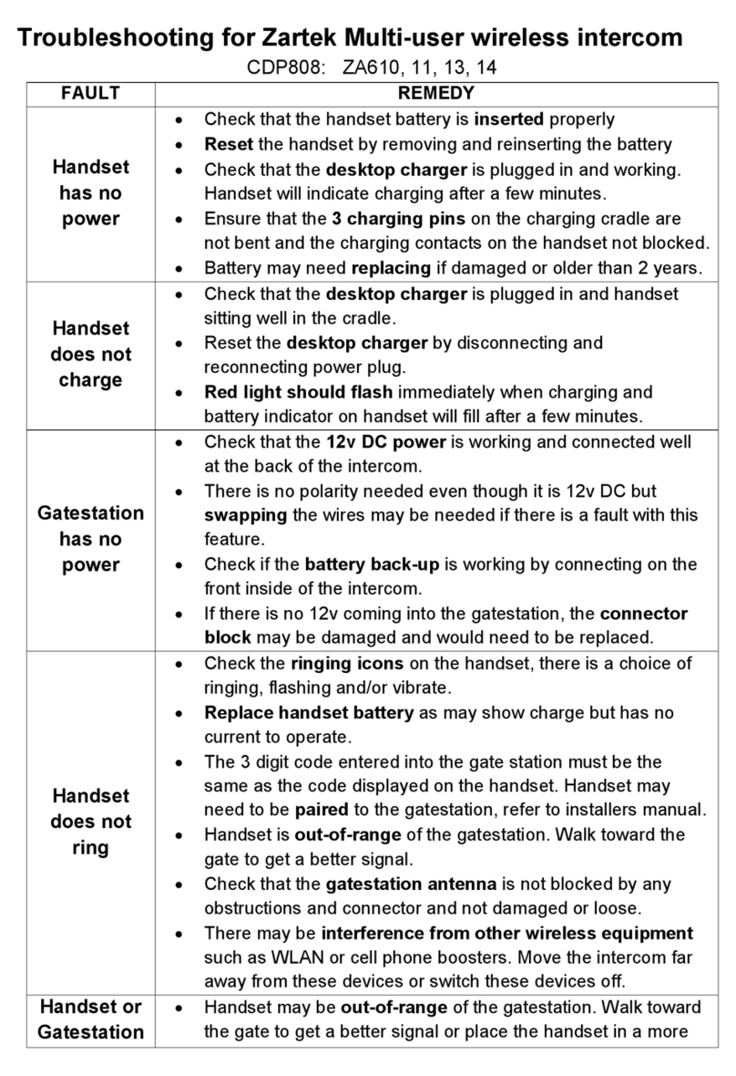
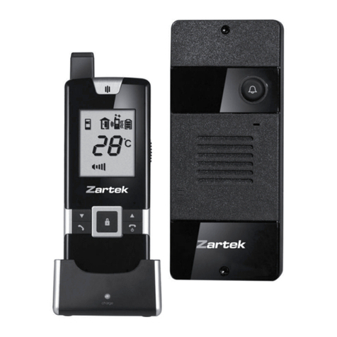
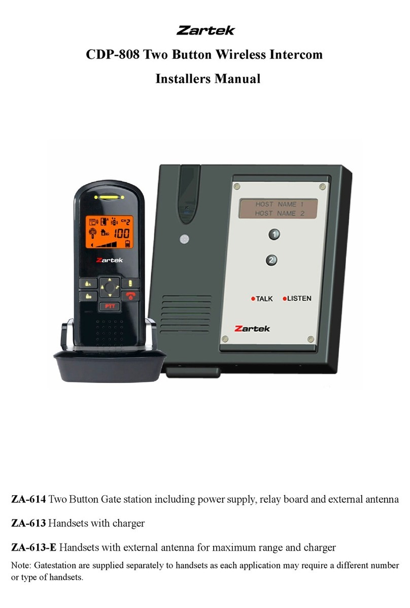
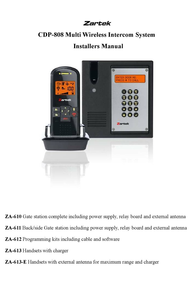
Zartek CDP-801 User manual


2

3
Getting Started
A. Power Supply
Caller unit
2. The caller unit operate with 12V DC supply. Connect the DC supply to the terminals
8at the back marked with .
12V DC
1.5A
1. With the supplied tool, loosen the screw that hold the front aluminum plate. The screws are
made special for anti-theft purpose, it is necessary to keep the tool in safe place as you need
it later when pairing new handsets.
Once the environment gets dark the name plate will be automatically illuminated if a DC supply is
connected.
8
CDP-805 manual_3.pdf 3 27/5/2017 12:21 PM

4
1. The supplied Li polymer battery pack is already installed in the handset. To replace, press
down the lock button 16 and slide open the battery door, take out the battery pack and
disconnect from socket 18 .
2. With the handset switched on, place it into the charger stand.
3. Plug in the supplied AC switching power supply into an AC outlet and connect its output plug
to the DC jack 21 located at the back of charger stand.
4. The charging indicator 20 should light up red during charging process. Adjust the position of
6. Now the unit is ready for operation. Either take out the unit or keep
placing it in the charger stand will cause no damage to the battery. In the latter case, when
the battery is being consumed and voltage falls to a certain level, the charger stand will
automatically charge up the battery. The segments inside the icon P will flash in turn
whenever the unit is under charging.
CAUTION : BESURE THE BATTERY IN HANDSET IS RECHARGEABLE TYPE BEFORE YOU
PLACE IT IN THE CHARGER STAND, OTHERWISE EXPLOSION MAY RESULT.
16 18
TO AC OUTLET
21 20
5. The battery pack should be fully charged up within 4 hours when used for the first time. All
segments inside the icon P will shown up and remain steady.
Handset
handset in charger stand in case this indicator does not light up. During charging, the
segments inside battery level icon P will flash in turn.
CDP-805 manual_3.pdf 4 27/5/2017 12:21 PM


6
C. Mounting of Caller Unit
INSERT RIVERTS INTO HOLES
(FOR CONCRETE WALL ONLY)
DRILLED
HOLES
1. The caller unit has been designed to be splash and rain proof. Ensure that the rubber seals and
battery cover are not removed.
2. Select a location near your door entrance where the surface is not rough. Some polishing may be
needed to get a smooth surface or otherwise the unit may not be able to be mounted securely.
3. It is advised that the mounting bracket is not installed on metal screening surfaces or in the vicinity of
other electronic devices that may reduce the operating range such as electric fences, cameras.
4. If it is unavoidable to mount against a metal surface ensure that the sides, top and front of the caller
unit are not shielded in any way. Wireless transmission will be affected and range reduced if there is
metal in close proximity.
5. Use the supplied self tap screws to fix the mounting bracket onto the wall. The supplied paper mask
at the end of this manual can be helpful in drilling the correct position of holes.
6. The 12V DC supply should be connected to the terminals marked at the back of caller unit. In
addition, there are also teminals marked and for connection to an electic door latch which
can be remotely opened by the handset. Where DC supply is available, the call button 1 2 3 4
will be automatically illuminated once the environment gets dark.
CAUTION : When using DC supply, in case the electric door latch does not function, reverse the
polaity connected ot and try again.
7. Align the two rivets on the mounting bracket with the holes of the metal hangers on the back of the
caller unit, make contact and slide the unit upward. Screw in the supplied machine screw to fix the
caller unit in position. Be sure the pairing switch 7 is set to NORMAL position.
8. Before you install back the aluminium alloy cover, you can print your name on the supplied translucent
PVC name plate and then cover by the name plate cover.
NAME PLATE
NAME PLATE
COVER
The caller unit is housed in a high impact ABS/PC cabinet strengthened by an aluminium alloy front cover
to achieve professional grade ruggedness required in most outdoor application. Rubber gaskets seals
around all joints and terminals keep out dust, rain, snow and spray, assuring years of reliable operation
HYHQLQKDUVKHQYLURQPHQW7KHXQLWPHHWVWR,3VWDQGDUGDQGFDQRSHUDWHIURPÝ&WRÝ&
12V DC
1.5A
12V DC
1.5A
CDP-805 manual_3.pdf 6 27/5/2017 12:21 PM


8
1. Call button
2. Call button
3. Call button
4. Call button
5. Call indicator
6. Microphone
7. Pairing button
8. Terminal block
9. Volume up button
10. Volume down button
11. Answer button
12. Hang up and power ON/OFF button
13. Door lock open button
14. Press-to-talk (PTT) button
15. Microphone
16. Battery door lock button
17. Speaker
18. Li battery socket
19. Charging contacts
20. Charging indicator
21. DC jack
.
22. Internal / External antenna selection switch
Controls Layout
Caller unit
Handset
20
21
Charging Stand
17
16
13
14
9
12
15
10
11
18
19
NORMAL
PAIRING
INT
EXT
5
6
1
1
1
2
3
4
2
3
4
8
7
22
CDP-805 manual_3.pdf 8 27/5/2017 12:21 PM

9
Caller unit doorbell ringing
Missed call
Reception mode
Out of range alert
Door chime alert selected
Flashing light alert selected
Vibrating alert selected
Door chime and
flashing light alert selected
LCD
J
K
L
M
N
O
P
Q
A
B
C
D
E
F
G
H
I
Door chime and
vibrating alert selected
Flashing light and
vibrating alert selected
Door chime, flashing light and
vibrating alert selected
Door lock opened
Caller unit battery low
Self battery low
Battery level
Speaker volume
Door lock de-activated
Flashing
Steady light up
Outdoor
temperature
Battery Level
Speaker volume
Door chime, flashing
light and vibrating
alert selected
Door lock de-activated
Missed call
Reception mode
Frontgate &
Backgate
doorbell ringing
Door lock
opened
Caller unit battery low
CDP-805 manual_3.pdf 9 27/5/2017 12:21 PM

9. Upon receiving a call, icon appears on the screen. The handset can answer the call by
pressing the Answer button 11 and the reception mode icon D will show up in LCD.
10
OPERATION
1. Switch on the handset by a long press (over 3 seconds) of the Power ON/OFF button 12 .
Press the same button again in case you want to switch off the unit.
2. The LCD screen will show up. In case the self battery low icon O appears and an alarm heard,
the battery has run down and need to be recharged by placing the unit into the charger stand.
During charging, the segments inside the battery level icon P will flash in turn irrespective the
unit is switched on or off. To protect battery, if the unit is not being re-charged when the icon
O shown up, it will be switched off automatically after 10 minutes.
3. To select the different methods of incoming call alert, press and hold the Volume Up/Down
buttons 9& 10 simultaneously for 2 sec to enter the selection mode. Use the Volume Up
9or Down button 10 to choose one of the seven alert methods, shortly press the Hang
up button 12 to confirm your selection and return to normal operation mode.
Depending on your selection, either one of the icons F to L will be shown on the screen. Note that
in case you select a combination with vibrating alert, the battery will run down more easily.
5. During conversation, the sound volume heard through the speaker 17 can also be adjusted
using buttons 9& 10 and the speaker volume icon Q will change correspondingly.
Please note the loudness of door chime is fixed and cannot be adjusted.
7. Make sure there is 12V DC power supply to the caller unit. Now press the Call button 1 , a
ding-dong tone will be heard and the Call indicator 5 starts flashing. Until a handset answers
the call, the ding-dong tone will be heard periodically, reminding the visitor to keep waiting. In
case there is no answer after 20 seconds, the caller unit ends the call by itself and the Call
indicator 5 goes off. Press the Call button 1 to initiate the call again.
-
N.B. When either a call button ( 1 2 3 or 4 ) is pressed, pending for reply from a handset or
during commurication, pressing the other 3 call buttons will not be recognised by the caller unit
to avoid interfering the existing call.
8. Once the call is being answered, the Call indicator 5 will light up steady and the ding-dong tone
stops ringing. Conversation can now be conducted by speaking into the Microphone 2 .
CDP-805 manual_3.pdf 10 27/5/2017 12:21 PM

11
Now conversation is possible and the voice of visitor can be heard from speaker 17 . To talk back
to visitor, press and hold the PTT button 14 and speak towards the Microphone 15 , reception
mode icon D goes off. Release PTT button 14 after finish speaking to listen to visitor, recep-
tion mode icon D show up again. It should be worth noted that the voice of visitor will not be
heard while pressing the PTT button 14 . Upon finish of conversation, press the Hang up button
12 to end the call.
This system has an automatic end call feature. In case the resident does not talk back to visitor
(i.e. press the PTT button
14 ) for over 90 sec, the call will be ended automatically. Such feature
is useful to protect your privacy in case you forget to end the call by pressing the Hang up button
12 .
10. Once a call has been answered, you can use the Door lock open button 13 to remotely open
the electric door latch for visitor (this function only available if there is 12V DC supply to the caller
unit and your door is equipped with an electric latch). Press the button 13 shortly, wait for 4-5
seconds and the icon M appears on the screen, showing the door latch is opened. The icon
M will disappear after 3 sec.
Under standby mode (i.e. when no call is set up between handset and caller unit), the electric
door latch can also be opened by long press of button 13 for over 2 sec. The Call indicator
5 on caller unit also light up for 2 sec.
To avoid misuse by children, this door lock opening function can be activated or deactivated.
When deactivated, pressing the button 13 will have no effect.
Deactivate door lock opening feature
Under normal operating mode, press shortly the button 10 , then within a period of 2 sec,
press shortly the button 13 . The Door lock de-activated icon B will show up on LCD
screen.
Activate door lock opening feature
Perform same procedure as above, the Door lock de-activated icon B will disappear from the
LCD screen.
11. For system equipped with several handsets, all the handsets will be alerted with an incoming call.
However, only the handset which first press the Answer button 11 can set up conversation
with caller unit. The remaining handsets will return to standby mode and their buttons become
de-activated until the conversation ends, making them impossible to interfere with the conversa-
tion.
CDP-805 manual_3.pdf 11 27/5/2017 12:21 PM

12
12. Under the circumstances of an unanswered call from a visitor (e.g. you are away from home or
located at a place which is out of range from the caller unit), the icon C will appear on the
screen. This icon is useful to remind you somebody has called. Press any button momentarily to
remove this icon.
13. Whenever handset is located at a spot which is outside the communication range of the caller
unit, an alarm will be heard and the icon E will appear on the screen. Such alarm cannot be
immediate and will alert you only when you are out of range for over 2 minutes (when 12V DC
supply is available or 20 minutes if battery is used). Press any button momentarily can stop the
alarm but the icon E still remains. Once handset falls back in range, the alarm will stop and the
icon E disappears.
15. The outdoor temperature indication provides you with an idea about the weather which is useful
if you plan to go outside of your home. When the system is first installed, the LCD will show the
default setting of - Ý&. Once the caller unit senses the outdoor temperature, the correct reading
will be shown on the LCD of handset. To obtain a correct reading of outdoor temperature, the
ventilation to temperature sensor 6should not be blocked.
16. Whenever the buttons (except PTT button 14 ) on handset are pressed, a tone will be heard to
validate your entry.
17. Once the Light sensor detects a low light intensity, the Call button on caller unit will become
automatically backlighted.
14. In case the DC supply to caller unit is cut off, the out of range icon E is shown and its
alarm will be heard.
CDP-805 manual_3.pdf 12 27/5/2017 12:21 PM

13
Intercom
This function is applicable only if you have two or more handsets in same apartment. Please note all
units must be paired together.
a. Under standby mode, momentarily press Answer button 11 , a “do – do” sound will be
heard.
b. The called handset will show the selected incoming call alert. Press Answer button 11 to
answer the call. The “do-do” sound on the calling handset will stop.
c. Now both handsets can converse with each other using the PTT button 14 .
d. Either party can press the Hang up button 12 to end the conversation.
e. The call will also be ended automatically if the PTT buttons 14 on either party is not pressed for
over 60 sec.
For system with more than two handsets, the incoming call alert on remaining handsets will stop once
the call is being answered. In case nobody answer the call, the alert will stop 20 seconds later.
N.B. Selective call of a particular handset is not possible. Whenever an handset initiates a call, all the
remaining units will be alerted and can answer to the call. However, only the unit who first press the
Answer button 11 can reply to the call, all others will be excluded from the intercom.
CAUTION : The two handests under intercom may not be able to detect a call from the caller unit. So
it is advisable to keep the intercom conversation short.
PRECAUTION
- Use only the supplied AC switching power supply. Use of other supply may cause damage to the
handset.
- Do not mix using old and new alkaline batteries in caller unit.
- When not using the doorphone for a long period of time, remove all batteries from handest and
caller unit to avoid battery leakage.
- Do not leave the handest expose to strong sunlight for a long period of time or near any heat
source, moisture and excessive dusty environment.
- Do not open the cabinet, no serviceable parts inside.
- When using for the first time, switch off the handset and charge up the supplied battery pack for
4 – 5 hours using the charger stand.
CDP-805 manual_3.pdf 13 27/5/2017 12:21 PM

14
TROUBLE SHOOTING GUIDE
Communication
distance
become short
Many steel structures between
Handset and Caller unit
Battery has run down
Relocate the position of Handset
Recharge battery in Handset using
charger stand.
Out-of-range alert
always on
No power supply to Caller unit
Distance between caller unit
and handset has exceeded the
range
Check DC supply to Caller unit.
Move handset & caller unit closer
together
Self battery low icon
always on
Battery pack is damaged and
cannot be recharged.
Replace new battery pack
Door latch cannot be
remotely opened by
handset
Door lock opening button 13
is deactivated
No DC supply to Caller unit
Wrong connection at terminal
block
Activate door lock opening button
13
Check if DC supply is available
Make proper connection
Cannot perform
intercom between
Handsets
The unit are not properly paired
Battery has run down
Perform pairing process
Recharge battery using charger
stand
Handset and
Caller unit cannot
communicate
Handset and Caller unit has
different ID code
Battery has run down
Perform pairing process
Recharge battery in Handset using
charger stand.
Problem Possible Causes Solution
CDP-805 manual_3.pdf 14 27/5/2017 12:21 PM

15

16
ø6 X 30mm (for concrete wall)
ø2 X 30mm (for wooden wall)
"
"
"
"
WIRE
INLET
MASK FOR HOLES DRILLING
CDP-805 manual_3.pdf 15 27/5/2017 12:21 PM
Other manuals for CDP-801
1
This manual suits for next models
1
Table of contents
Other Zartek Intercom System manuals