manuals.online logo
Brands
  1. Home
  2. •
  3. Brands
  4. •
  5. ZAUN24
  6. •
  7. Gate Opener
  8. •
  9. ZAUN24 GTS 180 User guide

ZAUN24 GTS 180 User guide

Gartentorschließer Camelion 180/170 Soft Close Garden Gate Closer GTS 180/170 Soft CloseMontageanleitung (DE)Mounting instruction (EN)© ZAUN24 / decoga GmbH - Otto-Hahn-Strasse 23 - 50997 Köln - Tel. +49 (0)2236 / 333 666 - Fax +49 (0)2236 / 333 66 5 - E-Mail: [email protected] - Stand: 02/2022
2
Vielen Dank für den Kauf des Gartentorschließers
Camelion GTS 180/170!
Bitte lies Dir die Montageanleitung gründlich durch,
um Fehler während der Montage zu vermeiden.
Ergänzend zu dieser Montageanleitung ndest Du
auf https://www.gartentorschließer.com einige Mon-
tagebeispiele und Montagevideos.
Solltest Du dann immer noch unsicher sein, wie der
Schließer am besten montiert wird, kontaktiere uns.
Wir helfen Dir sehr gerne weiter!
DE Thank you for purchasing the Garden Gate Closer
Camelion GTS 180/170!
Please read this mounting instruction carefully to
avoid any problem during mounting operations.
In additional to this mounting instruction we have
captured many real-life mounting examples in the
service section of our homepage for you: https://
gardengatecloser.com/
If you are unsure how to mount the gate closer
contact us. We are pleased to help you!
EN
(DE) Vorwort
(EN) Preface
(DE) Serviceanfragen
(EN) Support
Montagevideo GTS
Mounting video GTS
Dübelmontage
Mounting of dowels
© ZAUN24 / decoga GmbH - Otto-Hahn-Strasse 23 - 50997 Köln - Tel. +49 (0)2236 / 333 666 - Fax +49 (0)2236 / 333 66 5 - E-Mail: [email protected] - Stand: 02/2022
3
(DE) Wichtige Hinweise
(EN) Important notes
I.
Der Gartentorschließer ist auch für Gartentore mit
steigenden Torbändern geeignet.
DE The gate closer can also be mounted on gates with
rising door hinges.
EN
Die Gewindebolzen stehen bei der Auslieferung
schief. Das ist kein Produktionsfehler, da sie bei der
Montage gerade gezogen werden.
DE When delivered the threaded rods are not straight.
This is no mistake, because they will be automatical-
ly straightened during assemby.
EN
(DE) Reklamationsausschluss
(EN) Exclusion of complaints
II.
Bei der Verzinkung und Lackierung der Winkel und
Rohre sind Prozesslöcher technisch notwendig.
Dadurch kann es zu kleinen Fehlstellen rund um die
Prozesslöcher kommen. Diese Fehlstellen, die wir so
gut wie möglich nacharbeiten, sowie leichte Kratz-
spuren im Lack sind technisch nicht vermeidbar und
sind daher von der Reklamation ausgeschlossen.
DE When galvanizing and painting the brakets and
pipes, process holes are technically necessary.
This can lead to small imperfections around the
process holes. These small defects, as well as slight
scratches in the paint are technically unavoidable
and are therefore excluded from the complaint.
EN
© ZAUN24 / decoga GmbH - Otto-Hahn-Strasse 23 - 50997 Köln - Tel. +49 (0)2236 / 333 666 - Fax +49 (0)2236 / 333 66 5 - E-Mail: [email protected] - Stand: 02/2022
4
(DE) Werkzeug und Material
(EN) Tools and Material
III.
Benötigte Werkzeuge
Akkubohrer, 5 mm/10 mm-Metallbohrer, Inbus-
schraubendreher (4 mm), Wasserwaage, Maßband,
Stift, Hammer, Körner, zwei 13 mm Gabelschlüssel.
Optionale Materialien
Dübel und Schrauben, Beton/ Stein-Bohrer
DE
Tools needed
Cordless screwdriver, 5/10 mm metal drill, inbus
screwdriver (4mm), spirit level, measuring tape,
pen, hammer, center punch, two 13 mm open end
wrenches.
Optional materials
Dowels and screws, stone / concrete drill
EN
© ZAUN24 / decoga GmbH - Otto-Hahn-Strasse 23 - 50997 Köln - Tel. +49 (0)2236 / 333 666 - Fax +49 (0)2236 / 333 66 5 - E-Mail: [email protected] - Stand: 02/2022
5
(DE) Inhalt
(EN) Package contents
IV.
1 x Gartentorschließer GTS Camelion 180/170
1 x Stahlwinkel (Winkel 1): 80 oder 120 mm
1 x Stahlwinkel (Winkel 2): 60 mm lang
2 x Hutmuttern M8
2 x Sperrmuttern M8
4 x Filipp-Dübel M6
2 x Schrauben M6 x 30 mm
2 x Schrauben M6 x 40 mm
1 x Montageanleitung
DE 1 garden gate closer GTS Camelion 180/170
1 steel bracket (bracket 1): 80 or 120 mm
1 steel bracket (bracket 2): 60 mm
2 cap nuts M8
2 lock nuts M8
4 Filipp-dowels M6
2 screws M6 x 30 mm
2 screws M6 x 40 mm
1 mounting instructions manual
EN
1 x Universalmontageplatte
2 x Gewindestifte
2 x Stück Hutmuttern M8
2 x Stück Sperrmuttern M8
DE 1 universal mounting plate
2 threaded rods
2 cap nuts M8
2 lock nuts M8
EN
(DE) Optionales Zubehör
(EN) Optional accessories
V.
© ZAUN24 / decoga GmbH - Otto-Hahn-Strasse 23 - 50997 Köln - Tel. +49 (0)2236 / 333 666 - Fax +49 (0)2236 / 333 66 5 - E-Mail: [email protected] - Stand: 02/2022
6
(DE) Montageposition wählen
(EN) Select the mounting position
1.
Der Schließer kann an jeder beliebigen Position am
Gartentor angebracht werden (Oben, Unten oder in
der Mitte).
Wichtig ist, dass die Montagewinkel ausreichend
Halt am Pfosten bzw. Tor nden.
Der Schließer muss nicht waagerecht montiert
werden. Daher können auch Tore mit steigenden
Bändern mit dem Schließer bestückt werden. Die
Steigung darf bis zu 10% bzw. 5,7° betragen.
DE The gate closer can be mounted at the top, in the
middle or at the bottom of the gate.
It is important that the mounting brackets have
enough hold on the gate post or on the gate.
It is not necessary to mount the garden gate closer
horizontally. Therefore the gate closer can be moun-
ted on gates with rising door hinges. An angle up to
10% or 5.7° is allowed.
EN
© ZAUN24 / decoga GmbH - Otto-Hahn-Strasse 23 - 50997 Köln - Tel. +49 (0)2236 / 333 666 - Fax +49 (0)2236 / 333 66 5 - E-Mail: [email protected] - Stand: 02/2022
7
(DE) Mögliche Montagepositionen des ersten Winkels bei unterschiedlichen Anschlägen
(EN) Possible mounting positions of the rst braket with dierent door hinges
2.1
Mittig angeschlagene Scharniere. Bei mittig angeschla-
genen Scharnieren wird meist der 80 mm lange Montage-
winkel verwendet.
DE
Centrally located door hinges. With centrally located
door hinges the 80 mm long bracket is usually used.
EN
Seitlich angeschlagene Scharniere. Bei seitlich ange-
schlagenen Scharnieren wird meist der 120 mm lange
Montagewinkel verwendet.
DE
Side located door hinges. With side located door hinges
the 120 mm long bracket is usually used.
EN
3D Scharniere. Bei 3D Scharnieren wird meist der 80 mm
lange Montagewinkel in Kombination mit der Universal-
montageplatte verwendet.
DE
3D door hinges. With 3D door hinges the 80 mm long
bracket is used in combination with the universal mountig
plate.
EN
3D Scharniere. Die Universalmontageplatte kann um 45°
gedreht werden um die Seite B zu verlängern.
DE
3D door hinges. The universal mounting plate can be
mounted with an angle of 45° to lengthen side B.
EN
3D Scharniere. Die Universalmontageplatte kann um 90°
gedreht werden um die Seite B zu verlängern.
DE
3D door hinges. The universal mounting plate can be
mounted with an angle of 90° to lengthen side B.
EN
© ZAUN24 / decoga GmbH - Otto-Hahn-Strasse 23 - 50997 Köln - Tel. +49 (0)2236 / 333 666 - Fax +49 (0)2236 / 333 66 5 - E-Mail: [email protected] - Stand: 02/2022
8
(DE) Mögliche Montagepositionen des ersten Winkels
(EN) Possible mounting positions of the rst bracket
2.2
Montage an betonierten Pfeilern. Bei betonierten Pfei-
lern kann das Montagemaß oft nicht eingehalten werden.
In diesen Fällen kann die richtige Montageposition mit Hilfe
der Universalmontageplatte erreicht werden.
DE
Mounting on concrete posts. When the door hinges are
mounted on a concrete post, the mounting distances often
can not be reached. With help of the universal mounting
plate the right mounting position can be achieved.
EN
Montage an Wänden. Bei angrenzenden Wänden wird der
Montagewinkel an der Wand montiert. Die Länge der Seite
B darf dabei 0 oder auch negativ werden. Zur Bestimmung
der Länge A+B wird immer der absolute Betrag gerechnet.
Beispiel:
A = 120 mm
B= -30 mm
|A|+|B| = 150 mm
DE
Mounting on walls. On adjacent walls the mounting
bracket is mounted on the wall. The length of side B can be
zero or below. But to determine the length of both sides A
and B the absolute value of both is calculated.
Example:
A = 120 mm
B = -30 mm
|A|+|B| = 150 mm
EN
(DE) Wahl des richtigen Montagelochs
(EN) Selection of the right mounting hole
2.3
Es gibt kein richtiges oder falsches Montageloch an
den Montagewinkeln des Schließers. Wichtig ist,
dass die aufgespannten Seiten in etwa 150 mm be-
tragen.
Hinweis: Umso größer die Seite A ausfällt umso
mehr Kraft wird auf das Tor gebracht. Aber umso
mehr Kraft wird auch zum Önen des Tores be-
nötigt.
DE TThere are no right or wrong mounting holes on the
mounting brackets of the gate closer. The important
thing is that the lenght of both sides are about 150
mm.
Note: The longer side A becomes, the more force is
directed to the gate. But also the force needed to
open the gate will increase.
EN
© ZAUN24 / decoga GmbH - Otto-Hahn-Strasse 23 - 50997 Köln - Tel. +49 (0)2236 / 333 666 - Fax +49 (0)2236 / 333 66 5 - E-Mail: [email protected] - Stand: 02/2022
9
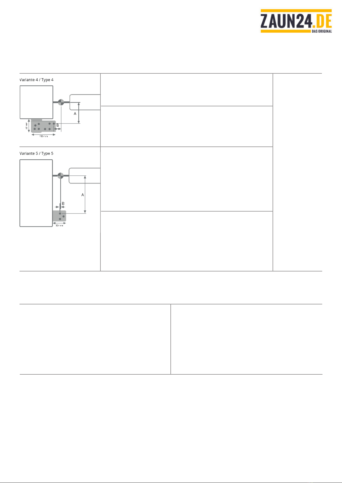
(DE) Montageposition und Montageloch des ersten Winkels bestimmen
(EN) Determine the mounting positions and mounting hole of the rst bracket
3.
Als erstes wird die Position des Winkels am Pfosten
bzw. der Wand bestimmt, indem der 80 mm oder
120 mm lange Winkel, oder die Kombination aus
dem 80 mm langem Winkel und der Universalmon-
tageplatte so positioniert wird, dass die aufgespann-
ten Seiten von A und B rund 150 mm ergeben.
Als Montageloch dient das Loch, mit dem die Bedin-
gung am besten erreicht werden kann. Dieses Loch
wird als Referenz für alle weiteren Schritte heran-
gezogen.
Der Winkel wird in dieser Position mit einer Zwinge
xiert.
DE At rst the position of the bracket that is mounted
on the gate post or wall will be determined. It is the
bracket with 80 mm or 120 mm in length, or a com-
bination of the 80 mm bracket and the universal
mounting plate. This bracket has to be positioned
in such a way that the lenght of both sides A and B
together equal 150 mm.
As mounting hole the hole is selected where the
condition A+B = 150 ts best. This hole is the refe-
rence for all folowing steps.
Once the position is found the bracket will be xed
with a clamp.
EN
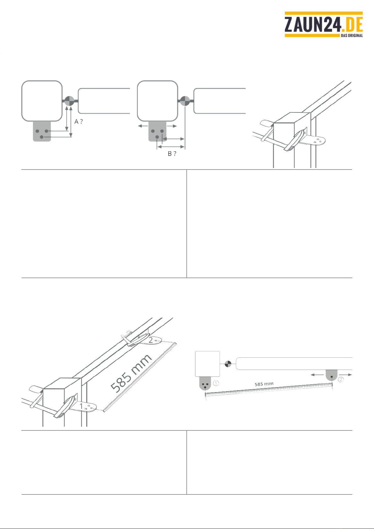
(DE) Montageposition des zweiten Winkels bestimmen
(EN) Determine the mounting positions of the second bracket
4.1
Als zweites wird die Position des Winkels am Tor
(Winkel 2) bestimmt, indem der 60 mm lange Winkel
so positioniert wird, dass der Loch-zu-Loch Abstand
585 mm ergibt.
Gemessen wird vom gewählten Montageloch des
ersten Winkels zum Montageloch des zweiten Win-
kels.
DE Now, the second bracket (bracket 2) must be posi-
tioned correctly on the gate.
For correct placement, the distance between the
two mounting holes (the selected mounting hole on
bracket 1 and the mounting hole on bracket 2) must
be 585 mm.
EN
© ZAUN24 / decoga GmbH - Otto-Hahn-Strasse 23 - 50997 Köln - Tel. +49 (0)2236 / 333 666 - Fax +49 (0)2236 / 333 66 5 - E-Mail: [email protected] - Stand: 02/2022
10
(DE) Horizontale Ausrichtung der Winkel prüfen
(EN) Level horizontal alignment of the brackets
4.2
Nachdem die Montagepositionen vorläug festge-
legt wurden, muss die horizontale Ausrichtung der
Winkel überprüft werden.
Hinweis: Da der Schließer auch bei steigenden To-
ren eingesetzt werden kann, ist eine leichte Schräg-
lage (bis 10% / 5°) der Winkel in Ordnung.
DE After the preliminary positions are found, the hori-
zontal alignment has to be checked.
Note: Due to the fact, that the closer can be used on
gates with rising hinges, a slight angle (up to 10% /
5°) is allowed.
EN
© ZAUN24 / decoga GmbH - Otto-Hahn-Strasse 23 - 50997 Köln - Tel. +49 (0)2236 / 333 666 - Fax +49 (0)2236 / 333 66 5 - E-Mail: [email protected] - Stand: 02/2022
11
(DE) Hub überprüfen
(EN) Check piston stroke
5.
Dieser Schritt dient der Überprüfung des maximal
ausgenutzten Hubs. Dazu wird das Tor geönet und
erneut der Loch-zu-Loch Abstand gemessen. Liegt
die Dierenz zu dem neu gemessenen Abstand (hier
430 mm) zwischen 140 mm und 160 mm wird der
Hub gut ausgenutzt.
Ist die Dierenz größer als 160 muss die Position
des ersten Winkels (Winkel 1) verändert werden.
Wiederholen Sie Schritt 3 und positionieren sie den
Winkel 1 so, dass der Abstand der beiden Dreh-
punkte verringert wird, oder wählen Sie ein anderes
Montageloch. Dann wiederholen Sie die Schritte 4
und 5 solange bis der Hub passt.
Hinweis: Der Hub kann auch geringer als 140-160
mm gewählt werden. Dann wird das Tor allerdings
schneller schließen. Bei einem Hub von 80mm wird
das Tor in rund 5 Sekunden geschlossen.
DE The next step is checking the correct piston stroke.
The door is opend and the hole-to-hole distance
measured. If the dierence to the new measured
distance (here 430 mm) lies between 140 mm and
160 mm the full piston stroke is used.
If the dierence is greater than 160 mm the position
of the rst bracket has to be corrected.
Please repeat step 3 and position bracket 1 so that
the sum of both sides (A+B) will be reduced or choo-
se another mounting hole. Also repeat also step 4
and 5 until the piston stroke is ok.
Note: The piston stroke can be smaller than 140-
160 mm, but then the door will be closed faster.
With a piston stroke of about 80 mm the gate will be
closed within 5 secounds.
EN
Beispiel / Example:
geschlossen / closed = 585 mm
oen / open = 445 mm
445 mm > 430 => ok
585 mm - 445 mm = 140 mm => ok
geschlossen / closed = 585 mm
oen / open = 415 mm
415 mm > 430 => not ok
© ZAUN24 / decoga GmbH - Otto-Hahn-Strasse 23 - 50997 Köln - Tel. +49 (0)2236 / 333 666 - Fax +49 (0)2236 / 333 66 5 - E-Mail: [email protected] - Stand: 02/2022
12
(DE) Winkel montieren
(EN) Mounting brackets
6.1
Genaue Arbeit sorgt für eine optisch ansprechende
Montage des Schließers. Markieren Sie die Bohrlö-
cher daher sehr genau und körnen Sie die Bohrlö-
cher in jedem Fall vor. Sonst kann es passieren, dass
der Bohrer verrutscht und das Bohrloch ungenau
wird.
DE Mark the drilling holes with a pen in the way so that
they are clearly visible.
We recommend to centre-punch the drilling holes in
order to prevent the metal drill from slipping o.
EN
Findet die Montage am Torpfosten oder dem Tor
statt kommen Filipp-Dübel zum Einsatz. Um diese
zu montieren wird ein 10 mm großes Loch benötigt.
Wir empfehlen das Loch mit einem 5 mm Bohrer
vorzubohren.
Um die Filipp-Dübel einzusetzen, wird der Dübel mit
einer M8 Mutter als Abstandshalter und einer M6
Schraube bestückt. Auf diese Weise kann der Dübel
bündig eingesetzt werden.
DE When mounting the bracket on the gate post or
gate Filipp-dowels are used. Therefore a 10 mm drill
hole is needed. We advice to predrill with a 5 mm
drill.
To mount the Filipp-dowel, the dowel is loaded with
a M8 nut as distance ring and a M6 screw. Now the
dowel can be hammered in ush.
EN
Dübelmontage
Mounting of dowels
© ZAUN24 / decoga GmbH - Otto-Hahn-Strasse 23 - 50997 Köln - Tel. +49 (0)2236 / 333 666 - Fax +49 (0)2236 / 333 66 5 - E-Mail: [email protected] - Stand: 02/2022
13
(DE) Winkel montieren
(EN) Mounting brackets
6.2
Nach dem Einsetzen des Filipp-Dübels, wird die
Schraube soweit angezogen, dass sich der Dübel
aufspreizt und im Pfosten / Tor Halt ndet.
Danach wird die Schraube samt Mutter wieder ent-
fernt.
DE After insertion of the Filipp-dowel the screw is fas-
tend, so that the dowel will be xed.
After xation of the dowel the screw and the nut are
removed.
EN
Nachdem die Dübel eingesetzt wurden muss nur
mehr der Winkel angesetzt und mit den Schrauben
xiert werden.
Am Pfosten werden die 40 mm langen Schrauben
eingesetzt. Am Tor kommen die 30 mm langen
Schrauben zum Einsatz.
DE After the mounting of the Filipp-dowels is com-
pleted, the bracket is xed using the appropriate
screws.
On the gate post the screws with 40 mm in lenght
are used. On the gate the 30 mm screws are used.
EN
© ZAUN24 / decoga GmbH - Otto-Hahn-Strasse 23 - 50997 Köln - Tel. +49 (0)2236 / 333 666 - Fax +49 (0)2236 / 333 66 5 - E-Mail: [email protected] - Stand: 02/2022
14
(DE) Schließer montieren
(EN) Mounting the gate closer
7.
Bevor der Schließer eingesetzt werden kann,
müssen die Sperrmuttern auf die Gewindestangen
gedreht werden. Die Sperrverzahnung zeigt nach
unten in Richtung Winkel.
Der Schließer wird jetzt mit der Hutmutter und der
Sperrmutter am Winkel festgezogen.
DE Before mounting the closer, the locking nuts have
to be screwed onto the threded rods. The locking
gearing has to be oriented down facing the bracket.
The closer is then xed by the locking nut and the
cap nut.
EN
Danach wird das Tor zur Hälfte geönet und die
Transportsicherung entfernt. Dazu wird der Schlie-
ßer leicht zusammengedrückt und der Sicherungs-
stift herausgezogen.
Danach fährt der Schließer aus. Während der Schlie-
ßer ausfährt wird der zweite Gewindebolzen in das
Montageloch an der Türe eingesetzt.
Sollte das nicht auf anhieb gelingen wird der Schlie-
ßer von Hand zusammengedückt und eingesetzt.
DE After xation, half open the gate and remove the
transport security. The closer drives out.
During the drive out the closer is mounted on the
gate.
If mounting did not work, please press the closer
together by hand and try again.
EN
© ZAUN24 / decoga GmbH - Otto-Hahn-Strasse 23 - 50997 Köln - Tel. +49 (0)2236 / 333 666 - Fax +49 (0)2236 / 333 66 5 - E-Mail: [email protected] - Stand: 02/2022
15
Deutsch
Wenn Du mit dem Gartentorschließer und unserem Support zufrieden bist, dann schenke uns doch eine Bewertung auf unse-
rer Homepage oder auf Amazon.de! Damit hilfst Du uns, leichter gefunden zu werden und Du hilfst anderen Menschen dabei,
eine geeignete Lösung für ihr Gartentor zu nden!
Danke!
English
If you are satised with your new garden gate closer and with our customer support, please give us your evaluation on our
website or on Amazon.co.uk! Thereby you help us to be found more easily, and you help others to nd the optimal solution
for their garden gate!
Thank you!
© ZAUN24 / decoga GmbH - Otto-Hahn-Strasse 23 - 50997 Köln - Tel. +49 (0)2236 / 333 666 - Fax +49 (0)2236 / 333 66 5 - E-Mail: [email protected] - Stand: 02/2022
16
BITTE LIES MICH!
PLEASE, READ ME!
Deutsch
Vielen Dank für den Kauf des Gartentorschließers GTS
180/170 Camelion! Damit bei der Montage alles klappt, ist
es wichtig die Situation deines Gartentores mit der passen-
den Montagevariante des Schließers abzustimmen. Das
genaue Lesen der beiliegenden Montageanleitung ist dabei
essenziell, damit der Gartentorschließer richtig montiert
wird und seine optimale Funktion gewährleistet ist!
Hast Du Fragen? Unser Support-Team steht Dir bei der
Montage bei, also zögere nicht uns zu kontaktieren!
English
Thank you for purchasing the Garden Gate Closer GTS
180/170 Camelion! It is of utmost importance that the situ-
ation of your garden gate matches the respective mounting
type of the gate closer for everything to work well during
assembly. In order to mount the garden gate closer cor-
rectly and therefore guarantee its optimal functioning it is
essential to read the mounting instruction carefully.
Any questions? Our support team assists you with the
mounting, so don’t hesitate to contact us!
KUNDENDIENST / SUPPORT
© ZAUN24 / decoga GmbH - Otto-Hahn-Strasse 23 - 50997 Köln - Tel. +49 (0)2236 / 333 666 - Fax +49 (0)2236 / 333 66 5 - E-Mail: [email protected] - Stand: 02/2022

This manual suits for next models

1

Popular Gate Opener manuals by other brands

Bandini Industrie GI.BI.DI. DSK40 Instructions for installations

Bandini Industrie

Bandini Industrie GI.BI.DI. DSK40 Instructions for installations

Casit MC300/IM WINCH manual

Casit

Casit MC300/IM WINCH manual

Roger Technology SMARTY Series INSTRUCTIONS AND RECOMMENDATIONS FOR THE INSTALLER

Roger Technology

Roger Technology SMARTY Series INSTRUCTIONS AND RECOMMENDATIONS FOR THE INSTALLER

SOMFY powered BLINDS Installation & programming guide

SOMFY

SOMFY powered BLINDS Installation & programming guide

Nice Mercury 310 Installation & reference manual

Nice

Nice Mercury 310 Installation & reference manual

Genius MISTRAL Series GUIDE FOR THE INSTALLER

Genius

Genius MISTRAL Series GUIDE FOR THE INSTALLER

CAME FA70230CB installation manual

CAME

CAME FA70230CB installation manual

WORKMASTER GO-A8-PW Operator's guide

WORKMASTER

WORKMASTER GO-A8-PW Operator's guide

SOMFY FX24 installation manual

SOMFY

SOMFY FX24 installation manual

Comunello Automation RAM 220 Installation and user manual

Comunello Automation

Comunello Automation RAM 220 Installation and user manual

SEA LEPUS 800 Fitting and Connection Instructions

SEA

SEA LEPUS 800 Fitting and Connection Instructions

Polaris Automatic Gate Operators 500 Series user manual

Polaris Automatic Gate Operators

Polaris Automatic Gate Operators 500 Series user manual

Chamberlain HDSW24UL installation manual

Chamberlain

Chamberlain HDSW24UL installation manual

Cardin HL Series manual

Cardin

Cardin HL Series manual

Merlin G950 Instructions for installation & use

Merlin

Merlin G950 Instructions for installation & use

Roger Technology BE20 Series INSTRUCTIONS AND RECOMMENDATIONS FOR THE INSTALLER

Roger Technology

Roger Technology BE20 Series INSTRUCTIONS AND RECOMMENDATIONS FOR THE INSTALLER

Chamberlain MIRACLE-ONE owner's manual

Chamberlain

Chamberlain MIRACLE-ONE owner's manual

SOMFY ELIXO 2000 230V RTS Installation manual - Illustrations

SOMFY

SOMFY ELIXO 2000 230V RTS Installation manual - Illustrations

manuals.online logo
manuals.online logoBrands
  • About & Mission
  • Contact us
  • Privacy Policy
  • Terms and Conditions

Copyright 2025 Manuals.Online. All Rights Reserved.