Zebra-Tech Hydro-Wiper L User manual

Hydro-Wiper L
Self-contained Anti-fouling Wiper for the
Seapoint Fluorometer
Installation and Operation Manual

Hydro-Wiper Installation and Operation Manual
Contents
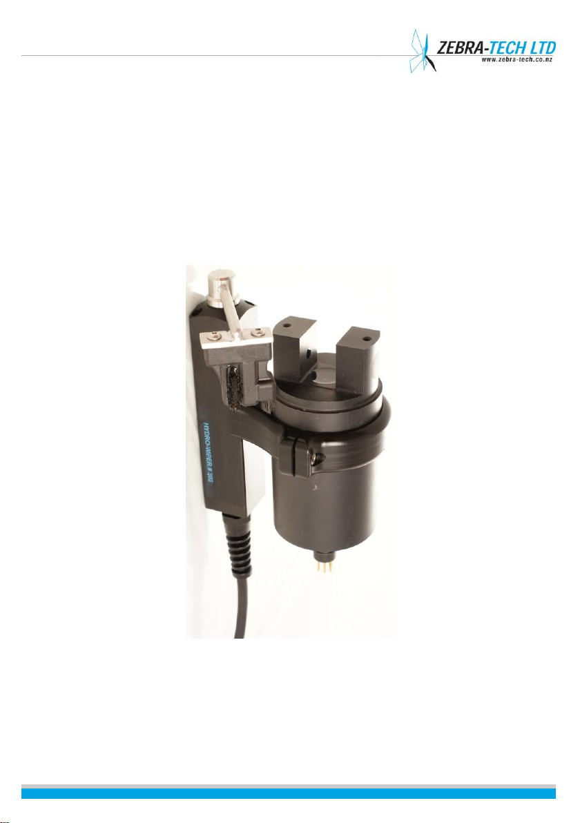
1. Hydro-Wiper at a glance........................................................................................... 1
Features ................................................................................................................. 2
2. Hydro-Wiper specifications ...................................................................................... 3
Specifications ......................................................................................................... 3
Options .................................................................................................................. 3
3. Hydro-Wiper components ........................................................................................ 4
Wiper body ............................................................................................................ 4
Wiper control housing ........................................................................................... 5
Electrical cable ....................................................................................................... 6
Field tool kit ........................................................................................................... 6
4. Preparing for deployment ........................................................................................ 7
Fitting the Seapoint Fluorometer into the instrument clamp................................ 7
Adjusting wiper brush pressure ............................................................................. 7
Mounting the wiper body ...................................................................................... 7
Mounting the wiper control housing ..................................................................... 8
Securing the wiper cable........................................................................................ 8
5. Operating the Hydro-Wiper...................................................................................... 9
Opening and closing the wiper control housing .................................................... 9
Installing the battery.............................................................................................. 9
Setting the wipe interval...................................................................................... 10
LED Status Indicator ............................................................................................. 11
During deployment .............................................................................................. 11
6. Maintenance.......................................................................................................... 12
Replaceable Hydro-Wiper parts........................................................................... 12
Servicing the Wiper Control Housing O-ring ........................................................ 12
7. Troubleshooting..................................................................................................... 13
Wipe failure ......................................................................................................... 13
Low battery shutdown ......................................................................................... 13
8. Further assistance .................................................................................................. 14

Hydro-Wiper Installation and Operation Manual
| 1 |
1. Hydro-Wiper at a glance
FIGURE 1: HYDRO-WIPER L WITH SEAPOINT FLUOROMETER FITTED
The Hydro-Wiper L is a mechanical wiper system designed to fit easily to the Seapoint
Fluorometer. Using a regular gentle brushing action, the Hydro-Wiper keeps the optical
window of the Seapoint Fluorometer clean from bio-fouling and other unwanted deposits
such as mud.
The Hydro-Wiper reduces the need for costly site visits to manually clean the instrument,
maintaining data integrity throughout long deployments.

Hydro-Wiper Installation and Operation Manual
| 2 |
Features
Your Hydro-Wiper L offers the following features:
Easy to install and simple to operate
Ultra-low power consumption for long term deployments
High precision wipe interval timing for minimal clock drift during long
deployments
Slip clutch protects gear box from damage if the wiper arm is knocked
Brush design that has been extensively field proven in extreme conditions
around the world
On board self monitoring for reliable operation; if the wiper arm is knocked
in front of the instrument face, the wiper arm automatically moves to one
side.

Hydro-Wiper Installation and Operation Manual
| 3 |
2. Hydro-Wiper specifications
Specifications
Wipe Interval:
User select (15, 30, 45, 60, 120, 180, 240, 300, 360 or 720 mins)
Clock Accuracy:
+/- 1 minute per year (0-40oC)
Power Supply:
6 x alkaline AA batteries
Power Consumption:
Quiescent, 0.02mA, ~80mA during a wipe
Deployment Endurance:
Wipe interval dependent. In excess of 4 months with a 2 hour
wipe interval
Brush:
User replaceable
Battery Housing O-ring:
#142 (2 3/8” x 3/32”)
Construction:
Passivated Stainless steel, Acetal
Wiper Shaft:
Multiple bearing support with quad ring seal
Depth Rating:
30 meters as standard
Cable:
EPDM jacketed cable between the wiper and battery housing
(1 meter standard length)
Cable Entry:
Cable glands with strain relief, O-ringed puck and resin back fill
TABLE 1: HYDRO-WIPER L SPECIFICATION TABLE
Options
The following additional options are also available with your Hydro-Wiper L product:
Extended Depth Rating:
100 meters
Connectors:
Impulse wet pluggable connectors on the wiper and/or battery
housing
Cable:
Additional cable between the wiper and battery housing
External Trigger:
External trigger input to control the wipe operation
TABLE 2: HYDRO-WIPER OPTIONAL EXTRAS

Hydro-Wiper Installation and Operation Manual
| 4 |
3. Hydro-Wiper components
Your Hydro-Wiper L is supplied as a fully self-contained and complete system. It consists of
the following components:
Wiper body, to which the Seapoint Fluorometer is attached
Wiper control housing. In addition to the batteries, the wiper control
housing contains the control electronics, power switch, wiper interval select
switch and diagnostic LED.
An electrical cable connecting the wiper body to the control housing
Field tool kit.
Wiper body
Seapoint
Fluorometer
Wiper Motor
and Gearbox
Wiper Brush
FIGURE 2: HYDRO-WIPER L BODY
Sensor
Clamp
Wiper Arm

Hydro-Wiper Installation and Operation Manual
| 5 |
The wiper body consists of:
Wiper motor and gearbox
Wiper shaft position sensing system
Wiper arm with brush.
Mounting clamp for the Seapoint Fluorometer.
Wiper control housing
The wiper control housing contains:
Batteries
Control electronics
On/off power switch
Wipe interval select switch
Diagnostic LED indicator.
FIGURE 3:
HYDRO-WIPER L
CONTROL HOUSING
FIGURE 4: INSIDE THE HYDRO-WIPER L CONTROL HOUSING

Hydro-Wiper Installation and Operation Manual
| 6 |
Electrical cable
The Hydro-Wiper L is fitted with 1 meter of cable between the wiper body and control
housing as standard. However, the length of cable required varies depending on the type
of installation. Additional cable can be fitted at the factory when the Hydro-Wiper is built.
Please specify the cable required when ordering.
Field tool kit
The field tool kit supplied with the Hydro-Wiper L contains:
Lid shifting tool
O-ring pick
Spare control housing O-ring
O-ring grease
Replacement set of batteries
Screwdriver for adjusting the wipe interval switch.

Hydro-Wiper Installation and Operation Manual
| 7 |
4. Preparing for deployment
Fitting the Seapoint Fluorometer into the
instrument clamp
Insert the Seapoint Fluorometer into the clamp so that the Hydro-Wiper brush swings
across the optical window of the Seapoint Fluorometer. The brush arm can be manually
moved to check the Seapoint Fluorometer is correctly positioned. Ensure the Hydro-Wiper
is switched off when manually rotating the wiper brush. Reposition the Seapoint
Fluorometer if necessary. Tighten the clamp set screw to secure the Seapoint Fluorometer
into the clamp.
Adjusting wiper brush pressure
The brush is mounted on an adjustable arm. The length of the arm controls the brush
pressure applied to the face of the Seapoint Fluorometer. This has been factory set and
should not need adjustment.
The success of the Hydro-Wiper is based on the brush sweeping lightly across the optical
window at regular intervals –it is not a scrubbing action. If there is excessive pressure, the
life of the brush will be reduced and damage to the optical surface of the Seapoint
Fluorometer may occur. If the brush pressure is insufficient, contact between the brush
and optical window will be lost in the centre of the window and fouling may occur.
If it is necessary to adjust the brush pressure, loosen the lock nut at the end of the wiper
arm and rotate the wiper arm in the desired direction. Tighten the lock nut after
adjustment.
Mounting the wiper body
Use the brackets located on the back of the wiper body to attach it to the desired
mounting structure.

Hydro-Wiper Installation and Operation Manual
| 8 |
Mounting the wiper control housing
Use the marine grade (316) stainless steel bracket attached to the wiper control
housing to attach the wiper control housing to the required structure.
Securing the wiper cable
Use cable ties to secure the wiper cable to avoid possible snags and fouling.
NOTE!
Avoid attaching the bracket directly to a metal structure. Doing so
can cause electrolysis, which may result in rapid deterioration of the
metal parts.
NOTE!
Do not allow the cable to constantly move with the water currents as
fatigue and eventual failure may result.

Hydro-Wiper Installation and Operation Manual
| 9 |
5. Operating the Hydro-Wiper
Opening and closing the wiper control housing
To open the wiper control housing, unscrew the lid in an anti-clockwise direction. If the lid
is tight, use the lid shifting tool supplied with your Hydro-Wiper. This tool fits into the
groove in the top face of the cap and allows greater leverage.
To close, screw the cap onto the battery housing until it is just hand tight. Do not over
tighten or use the cap shifting tool to tighten the cap.
NOTE!
Always clean and service the O ring before closing the lid. Refer to the
maintenance section of this manual for instructions on doing this.
Installing the battery
Switch off the Hydro-Wiper using the power switch. Gently pull the battery connector off
the battery holder contacts. Remove the battery holder from the control housing and
insert 6 x AA batteries into the battery holder. Check all the batteries are correctly
orientated. Put the battery holder back into the control housing. Re-attach the battery
connector to the battery holder contacts. Switch on the Hydro-Wiper. The LED should flash
4 times and then a wipe is performed.
NOTE!
Use only good quality AA 1.5 volt alkaline batteries (eg. Energizer or Duracell
brand).

Hydro-Wiper Installation and Operation Manual
| 10 |
Setting the wipe interval
The wipe interval is the period of time between the start of one wipe and the start of the
next wipe. This is controlled by the position of the wipe interval switch. Set the wipe
interval switch at the desired setting (refer to the table below) using the screwdriver
provided in the field kit.
NOTE!
Ensure the Hydro-Wiper is switched off when adjusting the wipe interval.
Wipe Interval Switch Position:
Wipe Interval:
0
15 minutes
1
30 minutes
2
45 minutes
3
60 minutes
4
120 minutes
5
180 minutes
6
240 minutes
7
300 minutes
8
360 minutes
9
720 minutes
TABLE 3: WIPE INTERVAL SELECT SWITCH SETTINGS
The optimal wipe interval will depend on environmental conditions at the field site.
Generally a wipe interval of 2 to 3 hours should prove sufficient to keep the sensor clean in
moderate fouling conditions.
The Hydro-Wiper wipe interval timer starts 0.5 seconds after the power is switched on. To
avoid the wiper affecting the sensor measurements, start the Hydro-Wiper out of sequence
with the measurement schedule. For example, if the sensor measurements are scheduled
every hour on the hour, start the Hydro-Wiper at 30 minutes past the hour.

Hydro-Wiper Installation and Operation Manual
| 11 |
LED Status Indicator
When the Hydro-Wiper is switched on the LED status indicator will blink 4 times and then a
wipe will be performed. During deployment the LED will blink every 15 seconds. The
number of blinks indicates the performance status of the Hydro-Wiper. Under normal
operation, the LED will blink once. If a fault exists, the LED will blink in a sequence as shown
in table 4.
LED Blink Sequence:
Status Description:
Once every 15 seconds
Normal operation
Twice every 15 seconds
Previous wipe failed
Three times every 15 seconds
Low battery shutdown
TABLE 4: LED INDICATOR BLINK SEQUENCE
During deployment
Unpredictable events can happen during a deployment. The Hydro-Wiper has been designed
to withstand the harsh nature of field deployments.
The wiper drive shaft features a slip mechanism, so the wiper arm can be manually
moved if necessary without causing any damage. This also protects the wipe
gearbox from damage in the event the wiper arm is subject to force or shock
loading during deployment.
The Hydro-Wiper routinely monitors the position of the wiper arm. If the wiper arm
is moved in front of the sensor, the Hydro-wiper will detect this and move the wiper
arm to one side.
If the wiper arm becomes jammed at any stage during a wipe, the direction of
rotation will be reversed in an attempt to dislodge the obstruction. If this is
unsuccessful, the Hydro-Wiper will abort the wipe. The diagnostic LED will flash
twice every 15 seconds whilst this situation continues.

Hydro-Wiper Installation and Operation Manual
| 12 |
6. Maintenance
Your Hydro-Wiper requires very little maintenance and should provide reliable operation
for many years.
Replaceable Hydro-Wiper parts
The only replaceable parts are the batteries and the wiper brush. Under normal conditions
the wiper brush should last many thousands of wipes. However, should your wiper brush
require replacement, these are inexpensive and can be obtained directly from Zebra-Tech
Ltd or your Hydro-Wiper reseller.
Servicing the Wiper Control Housing O-ring
Service the O-ring each time you open the wiper control housing and before deployment.
1
Using the O-ring pick provided with the Hydro-Wiper, carefully remove the
O-ring from the groove in the wiper housing.
2
Clean the O-ring, the O-ring groove and the sealing face on the inside of the
lid using a tissue.
3
Inspect the O-ring for cracks, deterioration or damage. Replace the O-ring if
necessary. A spare O-ring is provided in the field kit that is supplied with the
Hydro-Wiper.
4
Wipe some of the O-ring grease provided with your Hydro-Wiper onto the O-
ring and the sealing face on the inside of the lid.
5
Replace the O-ring into the groove in the battery housing.

Hydro-Wiper Installation and Operation Manual
| 13 |
7. Troubleshooting
Wipe failure
Should the wiper arm jam during a wipe due to an obstruction, it will attempt to dislodge
itself by undergoing a series of direction reversals. If unsuccessful, the wipe will be aborted,
and the LED will blink 3 times every 15 seconds until the next wipe is due.
NOTE!
The Hydro-Wiper is not damaged in the event of the wiper arm becoming
completely jammed by an obstruction.
NOTE!
The LED indicator will blink twice every 15 seconds when the Hydro-Wiper
has failed to complete the last scheduled wipe.
Low battery shutdown
Low battery shutdown occurs when the battery pack reaches around 6.5 volts. No wipes
will be performed when the Hydro-Wiper is in low battery shutdown mode.
NOTE!
The LED indicator will blink three times every 15 seconds when the Hydro-
Wiper is in low battery shutdown mode.

Hydro-Wiper Installation and Operation Manual
| 14 |
8. Further Assistance
For further assistance with this or any other Zebra-Tech product, please contact:
Zebra-Tech Ltd
PO Box 1668
Nelson 7040
New Zealand
Tel: International 0064 3 548 0468
Fax: International 0064 3 548 0466
Email: [email protected]
Hydro-Wiper models currently available
Hydro-Wiper Model:
Instrument:
Hydro-Wiper A
Seapoint Turbidity Meter
Hydro-Wiper B
D&A OBS 3
Hydro-Wiper C
D&A OBS 3+
Hydro-Wiper D
Aqualogger 200
Hydro-Wiper E
Aqualogger 210
Hydro-Wiper F
Chelsea TriLux
Hydro-Wiper G
RBR XR-420
Hydro-Wiper H
LiCor Li-192
Hydro-Wiper I
TriOS Ramses-ACC
Hydro-Wiper J
Turner Designs Cyclops-7
Hydro-Wiper K
D&A OBS-3A
Hydro-Wiper L
Seapoint Fluorometer
Hydro-Wiper M
Eco Triplet
Hydro-Wiper N
Apogee PAR
For up to date information about the Hydro-Wiper and other models available, please visit
the Zebra-Tech Ltd website at: http://www.zebra-tech.co.nz.
Proudly designed and manufactured in New Zealand
Table of contents
Other Zebra-Tech Ultrasonic Jewelry Cleaner manuals