Zebra-Tech Hydro-Wiper User manual

SELF-CONTAINED HYDRO-WIPER
OPERATION MANUAL
English.01/2018.V1.0

TABLE OF CONTENTS
1. INTRODUCTION.................................................... 3
Features.................................................................................. 4
2. HYDRO-WIPER SPECIFICATIONS........................5
Options.....................................................................................6
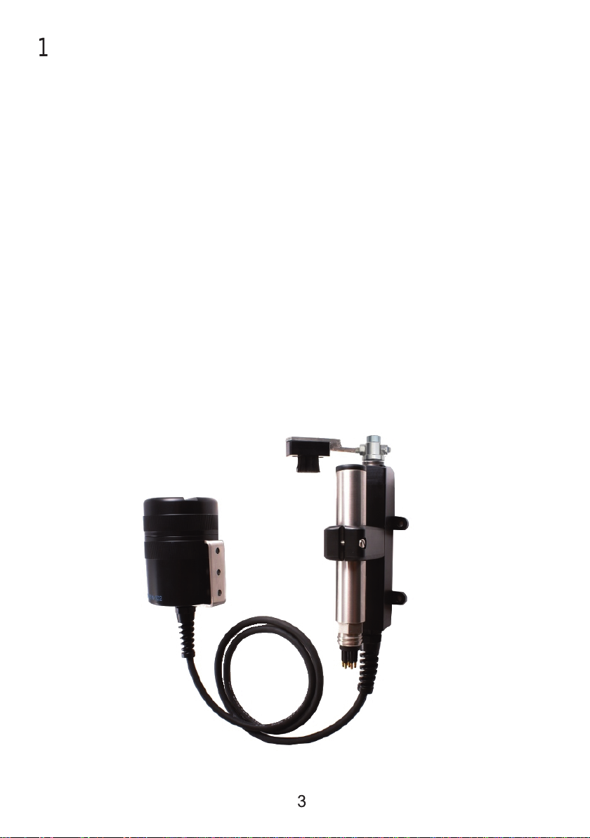
3. HYDRO-WIPER COMPONENTS............................7
Wiper body...............................................................................7
Wiper control housing..............................................................8
Electrical cable.........................................................................9
Field tool kit..............................................................................9
4. PREPARING FOR DEPLOYMENT.........................10
Fitting your sensor into the Hydro-Wiper clamp.....................10
Adjusting the wiper brush pressure........................................ 10
Securing the wiper cable.........................................................12
Mounting the wiper control housing....................................... 12
5. OPERATING THE HYDRO-WIPER........................13
Opening and closing the wiper control housing..................... 13
Installing the battery................................................................13
Setting the wipe interval..........................................................14
Adjusting the wipe angle.........................................................15
Battery endurance...................................................................15
LED status indicator................................................................17
During deployment..................................................................17
6. MAINTENANCE.....................................................18
Replaceable Hydro-Wiper parts..............................................18
Servicing the wiper control housing O-Ring........................... 18
7. TROUBLESHOOTING...........................................19
Wipe failure..............................................................................19
Low battery shutdown............................................................ 19
8. FURTHER ASSISTANCE.......................................20

The Hydro-Wiper is a mechanical wiper system designed to fit
easily to a variety of optical instruments. Using a regular gentle
brushing action, the Hydro-Wiper keeps the optical window of the
instrument clean from bio-fouling and other unwanted deposits
such as mud. The Hydro-Wiper reduces the need for costly site
visits to manually clean the instrument, maintaining data integrity
throughout long deployments.
This manual is supplied with all standard self-contained Hydro-
Wipers and provides an overview of installation and operation. If
technical assistance is required, please do not hesitate to contact
Zebra-Tech. Our contact details are on the contact page.
3
1.INTRODUCTION

Your Hydro-Wiper offers the following features:
•Easy to install and simple to operate
•Ultra-low power consumption for long term deployments
•High precision wipe interval timing for minimal clock drift
during long deployments
•Adjustable wipe angle
•Customisation
•Very robust for harsh field conditions
•Brush design that has been extensively field proven in
extreme conditions around the world
•On board self-monitoring for reliable operation; if the wiper
arm is knocked in front of the instrument face, the wiper
arm automatically moves to one side.
FEATURES
4

2. HYDRO-WIPER SPECIFICATIONS
5
Brush: User replaceable
Battery Housing O-ring: #142 (2 3/8”x 3/32”)
Cable: EPDM jacketed cable between the wiper
and battery housing (1 meter standard
length)
Cable Entry: 30m Rated - Cable glands with strain
relief, O-ringed puck and resin back fill.
100m Rated - Teledyne connector
Clock Accuracy: +/- 1 minute per year (0-40oC)
Construction: Passivated Stainless steel, Acetal
Power Supply: 6 x alkaline AA batteries
Power Consumption: Quiescent, 0.02mA, ~80mA during a
wipe
Deployment Endurance: Wipe interval dependent. In excess of 6
months with a 2 hour wipe interval
Depth Rating: 30 meters as standard, 100m option
Wipe Interval: User select (15, 30, 45, 60, 120, 180,
240, 300, 360 or 720 mins)
TABLE 1: HYDRO-WIPER SPECIFICATIONS

6
The following options are available with your Hydro-Wiper
Connectors: Teledyne Impulse wet pluggable
connectors on wiper and /or
battery housing
Cable: Additional cable between the
wiper and battery housing
Customization: Custom clamps, brushes and
arms
Extended Battery Housing: Twice the number of batteries
(12) for extended deployment
Extended Depth Rating: 100 meters
Multi-Wipe : Wipe up to 3 sensors per
Hydro-Wiper. Only available for
Turners Cyclops and Odyssey
sensors.
TABLE 2: HYDRO-WIPER OPTIONS
OPTIONS

7
3.HYDRO-WIPER COMPONENTS
Your Hydro-Wiper is supplied as a fully self-contained and
complete system. It consists of the following components:
•Wiper body, to which the instrument is attached
•Wiper control housing. In addition to the batteries, the
wiper control housing contains the control electronics,
power switch, wiper interval select switch and status LED.
•An electrical cable connecting the wiper body to the control
housing
•Field tool kit.
The wiper body consists of:
•Wiper motor and gearbox
•Wiper shaft position sensing system
•Wiper arm with brush.
•Mounting clamp for the optical instrument.
•Anode
WIPER BODY

The wiper control housing contains:
•Batteries
•Control electronics
•On/off power switch
•Wipe interval select switch
•Adjustable wipe angle pots
•Diagnostic LED indicator
8
WIPER CONTROL HOUSING
Wipe interval
selector switch
Wipe angle
adjustment
controls
On/Off Switch
Electrical cable gland Mounting
bracket
Lid
LED Indicator

ELECTRICAL CABLE
9
The Hydro-Wiper is fitted with 1 meter of cable between the wiper
body and control housing as standard. However, the length of
cable required may vary depending on the type of installation.
Additional cable can be fitted at the factory when the Hydro-Wiper
is built. Please specify the cable required when ordering.
FIELDTOOL KIT
The field tool kit supplied with the Hydro-Wiper contains:
•Lid shifting tool
•Spare control housing O-ring
•O-ring grease
•Set of batteries

4.PREPARING FOR DEPLOYMENT
1 0
If you require technical assistance fitting the Hydro-Wiper to your
instrument, please contact Zebra-Tech. See contact page for our
details.
FITTINGYOUR SENSOR INTO THE HYDRO-WIPER CLAMP
ADJUSTINGWIPER BRUSH PRESSURE
The success of the Hydro-Wiper is based on the brush sweeping
lightly across the sensor window at regular intervals –it is not a
scrubbing action. If there is excessive pressure, the life of the
brush will be reduced and damage to the sensor surfaces may
occur. If the brush pressure is insufficient, contact between the
brush and optical window will be lost and fouling may develop.
There are two methods to adjust the brush pressure depending on
the orientation of the brush. Vertical brushes are for instruments
with the windows on the side. Horizontal brushes are for
instruments with optical window on top of the sensor.
1. Vertical brushes:
The brush is mounted on an adjustable arm. The length of the arm
controls the brush pressure applied to the face of the sensor. This
is generally factory set and should not need adjustment unless you
are changing sensors.
Ensure the Hydro-Wiper is switched off when manually
rotating the wiper brush.

If it is necessary to adjust the brush pressure, loosen the nuts on
the wiper arm and rotate the wiper arm in the desired direction.
Tighten the nuts after adjustment.
2. Horizontal brushes:
The brush pressure can easily be adjusted by sliding the sensor
upwards or downwards in the clamp. Do this by loosening the
clamp screw and tightening again once you have made the
desired adjustment.
11
Horizontal Brush - Adjust
clamp
Vertical Brush - Adjust arm

1 2
NOTE!
Avoid attaching the bracket directly to a metal structure.
Doing so can cause electrolysis, which may result in rapid
deterioration of the metal parts.
Use cable ties to secure the wiper cable to avoid possible snags
and fouling.
NOTE!
Do not allow the cable to constantly move with the water
currents as fatigue and eventual failure may result.
SECURINGTHE WIPER CABLE
Use the marine grade (316) stainless steel bracket attached to
the wiper control housing to attach the wiper control housing to
the required structure.
MOUNTINGTHE WIPER CONTROL HOUSING

5.OPERATINGTHE HYDRO-WIPER
1 3
OPENINGAND CLOSING THEWIPER CONTROL HOUSING
To open the wiper control housing, unscrew the lid in an anti-
clockwise direction. If the lid is tight, use the lid shifting tool
supplied with your Hydro-Wiper. This tool fits into the groove in the
top face of the cap and allows greater leverage.
To close, screw the cap onto the battery housing until it is just hand
tight. Do not over tighten or use the cap shifting tool to tighten the
cap.
NOTE!
Always clean and service the O ring before closing the
lid. Refer to the maintenance section of this manual for
instructions on doing this.
INSTALLINGTHE BATTERY
Switch the power switch to the off position. Gently pull the battery
connector off the battery holder contacts. Remove the battery
holder from the control housing and insert 6 new AA batteries into
the battery holder. Check all the batteries are correctly orientated.
Put the battery holder back into the control housing. Re-attach the
battery connector to the battery holder contacts. Switch on the
Hydro-Wiper. The LED should flash 4 times and then a wipe is
performed.
NOTE!
Use only good quality AA 1.5 volt alkaline batteries (eg.
Energizer or Duracell brand).

SETTINGTHE WIPE INTERVAL
1 4
The wipe interval is the period of time between the start of one
wipe and the start of the next. The optimal wipe interval will
depend on environmental conditions at the field site. Generally a
wipe interval of 2 to 3 hours should prove sufficient to keep the
sensor clean in moderate fouling conditions.
The wipe interval is controlled by the position of the wipe interval
switch. Refer to table 3 on page 14 and set the wipe interval
switch at the desired setting as shown in the photo below.
NOTE!
Ensure the Hydro-Wiper is switched off when adjusting
the wipe interval.

ADJUSTINGTHE WIPEANGLE AND PARK POSITION
1 5
Switch Position: Wipe Interval: Battery Endurance (days)
0 15 minutes 81
1 30 minutes 157
2 45 minutes 229
3 60 minutes 298
4 120 minutes 538
5 180 minutes 735
6 240 minutes 901
7 300 minutes 1042
8 360 minutes 1163
9 720 minutes 1639
TABLE 3: WIPE INTERVAL SELECT SWITCH SETTINGS
*Assumes new Energizer AA batteries using a standard Hydro-Wiper.
Extended Deployment Hydro-Wiper also available.
The Hydro-Wiper wipe interval timer tart 0.5 econd after the
power i witched on.
WIPE INTERVALAND ESTIMATED BATTERY ENDURANCE (DAYS)*
Both the wipe angle and park position of your Hydro-Wiper have
been factory set to suit the sensor for which it was built. However,
there may be circumstances when you would like to alter these.
This may arise when converting your Hydro-Wiper for use with a
different instrument.
To adjust either the wipe or the park position, unscrew the lid from
the wiper control housing. Locate the blue controls as pictured
below.

1 6
For both controls, turning clockwise will increase the angle.
Turning counter-clockwise will decrease the angle. Park position
determines where the wiper will stop between wipes. Wipe angle
determines how far the wiper will sweep.
Park Po ition
Wipe Angle
NOTE!
Ensure the Hydro-Wiper is switched off when adjusting
the wipe angle or park position, changes only take effect
on power-up.
Park Position
Wipe angle

1 7
LED STATUS INDICATOR
When the Hydro-Wiper is switched on the LED status indicator will
blink 4 times and then a wipe will be performed. During
deployment the LED will blink every 15 seconds. The number of
blinks indicates the performance status of the Hydro-Wiper as
shown in table 4.
DURING DEPLOYMENT
Unpredictable events can happen during a deployment. The Hydro-
Wiper has been designed to withstand the harsh nature of field
deployments.
•The wiper drive shaft features a slip mechanism, so the
wiper arm can be manually moved if necessary without
causing any damage. This also protects the wipe
gearbox from damage in the event the wiper arm is
subject to force or shock loading during deployment.
•The Hydro-Wiper routinely monitors the position of the
wiper arm. If the wiper arm is moved from the park position,
the Hydro-Wiper will detect this and move the wiper arm to
one side.
•If the wiper arm becomes jammed at any stage during a
wipe, the direction of rotation will be reversed in an
attempt to dislodge the obstruction. If this is unsuccessful,
the Hydro-Wiper will abort the wipe. The diagnostic LED will
flash twice every 15 seconds whilst this situation continues.
LED Blink Sequence: Status Description:
Once every 15 seconds Normal operation
Twice every 15 seconds Previous wipe failed
Three times every 15 seconds Low battery shutdown
TABLE 4: LED STATUS INDICATOR BLINK SEQUENCE

1 8
6.MAINTENANCE
Your Hydro-Wiper requires very little maintenance and should
provide reliable operation for many years.
REPLACEABLE HYDRO-WIPER PARTS
The only replaceable parts are the batteries, wiper brush and anode.
Under normal conditions the wiper brush should last many
thousands of wipes. However, should your wiper brush require
replacement, these are inexpensive and obtainable directly from
Zebra-Tech Ltd or your Hydro-Wiper reseller.
Anodes reduce corrosion of the Hydro-Wiper shaft in harsh
environments. Replacement anode buttons can be purchased from
Zebra-Tech or your local Hydro-Wiper reseller. To replace the anode
button, simply unscrew the old one and swap it.
From 2017, anodes have been supplied with new Hydro-Wipers as
standard. However, anodes can be added to legacy Hydro-Wipers.
Please contact Zebra-Tech for more information.
SERVICINGTHE WIPER CONTROL HOUSING O-RING
Service the O-ring each time you open the wiper control housing
and before deployment.
1 Carefully remove the O-ring from the groove in the wiper
control housing.
2 Clean the O-ring, the O-ring groove and the sealing face
on the inside of the lid using a tissue.
3 Inspect the O-ring for cracks, deterioration or damage.
Replace the O-ring if necessary. A spare O-ring is
provided in your Hydro-Wiper field kit.
4 Wipe some O-ring grease onto the O-ring and the sealing
face on the inside of the lid.
5 Replace the O-ring into the groove in the battery housing.

1 9
7.TROUBLESHOOTING
WIPE FAILURE
Should the wiper arm jam during a wipe due to an obstruction, it
will attempt to dislodge itself by undergoing a series of direction
reversals. If unsuccessful the wipe will be aborted and the LED will
blink 3 times every 15 seconds until the next wipe is due.
NOTE!
The Hydro-Wiper is not damaged in the event of the wiper
arm becoming completely jammed by an obstruction.
NOTE!
The LED indicator will blink twice every 15 seconds when
the Hydro-Wiper has failed to complete the last scheduled
wipe.
LOW BATTERY SHUTDOWN
Low battery shutdown occurs when the battery pack reaches
around 6.5 volts. No wipes will be performed when the Hydro-
Wiper is in low battery shutdown mode.
NOTE!
The LED indicator will blink three times every 15 seconds
when the Hydro-Wiper is in low battery shutdown mode.

20
For further assistance with this or any other Zebra-Tech product,
please contact:
Zebra-Tech Ltd
PO Box 1668
Nelson 7040
New Zealand
Tel: International 0064 3 548 0468
Fax: International 0064 3 548 0466
Email: [email protected]
For up to date information about the Hydro-Wiper and other
products available, please visit the Zebra-Tech Ltd website at:
www.zebra-tech.co.nz
Proudly designed and manufactured in New Zealand
8.FURTHERASSISTANCE
Other Zebra-Tech Ultrasonic Jewelry Cleaner manuals