ZEKS HeatSink HSG Series User manual

TECHNICAL MANUAL
HeatSink
True-Cycling Refrigerated
Compressed Air Dryers
HSG Models
200-400 SCFM
ZEKS Compressed Air Solutions
1302 Goshen Parkway
West Chester, PA 19380
Phone: 610-692-9100
800-888-2323
Fax: 610-692-9192
Web: www.zeks.com
Form: TM 200-400HSG-0118
Patent No.: 6,186,223
NOTICE
Those operating the machine or performing
maintenance should read and understand the
decals positioned on the machine and
contents of this Technical Manual.
Ensure that this Technical Manual is not
removed permanently from the machine.
TM

TABLE OF CONTENTS PAGE
1. INTRODUCTION 2
2. ABBREVIATED WARRANTY 2
3. REFRIGERATED DRYER NOMENCLATURE 3
4. RECEIVING AND INSPECTION 4
5. SAFETY AND OPERATION PRECAUTIONS 5
6. PRINCIPLES OF OPERATION 8
7. INSTALLATION AND INITIAL START-UP 14
8. SCHEDULED MAINTENANCE 17
9. TROUBLESHOOTING 19
10. WIRING DIAGRAMS 21
11. GENERAL ARRANGEMENT 23
12. PARTS IDENTIFICATION 24
13. ENGINEERING SPECIFICATIONS 25
TECHNICAL MANUAL
HeatSink
True-Cycling Refrigerated Compressed Air Dryers
HSG Models
200-400 SCFM
TM

2. ABBREVIATED WARRANTY
ZEKS refrigerated dryers are warranted to be free from defects in material and
workmanship for a period of 12 months from the original date of shipment from the factory.
To allow the warranty to be in effect for 12 months from the date of equipment start-up,
the Warranty Registration Card must be completed and returned to ZEKS. Alternately,
the Warranty Registration Card may be completed online at www.zeks.com. The total
warranty period cannot exceed 18 months from the original date of shipment from
the factory.
Equipment must be installed and operated in accordance with ZEKS’ recommendations.
ZEKS liability is limited to repair of, refund of purchase price paid for, or replacement in
kind at ZEKS’ sole option, during the warranty time period stated above. IN NO EVENT
SHALL ZEKS BE LIABLE OR RESPONSIBLE FOR INCIDENTAL OR CONSEQUENTIAL
DAMAGES, even if the possibility of such incidental or consequential damages has been
made known to ZEKS Compressed Air Solutions. In addition, the usual maintenance and
replacement type products are not covered by this warranty.
REFRIGERANT COMPRESSORS
A prorated warranty for the replacement of the refrigerant compressor will be extended
to a maximum of 60 months (5 years) from the original date of shipment from the factory.
Following the standard warranty terms, the available prorated compressor warranty is as
stated below. This prorated warranty applies to replacement compressor only and does
not cover any labor expenses.
Prorated coverage of price from date of shipment from the factory:
19 to 24 months 70%
25 to 36 months 50%
37 to 48 months 30%
49 to 60 months 10%
2
1. INTRODUCTION
ZEKS HeatSink™ refrigerated air dryers remove moisture, oil vapor, and
other contaminants from compressed air. These contaminants are detrimental
to pneumatically operated appliances, controls, instruments, machinery and
tools. This removal is accomplished by cooling the air with a refrigeration unit
to a temperature at which moisture in the air is condensed and separated from the air
stream. The temperature the air is cooled to, normally between 34°F and 38°F (1°C -
3°C), is known as dew point. This dryer can be easily installed into various pneumatic
systems in which dry air is required or desired. Please refer to Principles of
Operation for complete operating details.
• For warning label information with French translations, refer to pages 5 and 6.
• Pur obtenir l’informatione des etiquettes dangereuses avec la traductione en francais, s’il vous plait
consul ter les pages 5 and 6.

3
HEAT EXCHANGERS
Dryers that utilize CFX heat exchanger technology are covered for a total of 10 years from
the original date of shipment from the factory. Following the standard warranty terms the
available warranty is as stated below. The exchanger warranty applies to the replacement
exchanger only and does not cover any labor expenses.
Prorated coverage of prices from date of shipment from the factory:
12 to 36 months 100%
37 to 48 months 70%
49 to 60 months 50%
61 to 84 months 30%
85 to 96 months 20%
97 to 120 months 10%
Freight and labor coverage varies internationally. Refer to Distributor Warranty Guidelines
for limitations and detailed explanation of warranty coverage.
The warranties expressed above are in lieu of and exclusive of all other warranties.
There are no other warranties, expressed or implied, except as stated herein. There are
noim-plied warranties of merchantability or fitness for a particular purpose, which are
specifically disclaimed.
3. REFRIGERATED DRYER NOMENCLATURE
NOMINAL*
FLOW DESIGN CONDENSER
SCFM TYPE SERIES TYPE POWER OPTIONS
200 HS= HeatSink G A = Air Cooled 2 = 230-1-60
250 W = Water Cooled 3 = 220-1-50
300 4 = 460-3-60
400 5 = 230-3-60
6 = 575-3-60
O = STANDARD O = STANDARD
G = ANALOG GAUGES F = COLD MIST ELIMINATOR
H = NEMA 4/12 Z = SPECIAL
K = G + H 8 = DPCTM Plus
L = G + W
W = WEATHERPROOF
* Nominal Flows indicated are for 100°F inlet temperature, 100°F ambient temperature
and 100 psig compressed air pressure.

4
4. RECEIVING AND INSPECTION
4.1 INSPECTION
Upon receipt of your ZEKS air dryer, inspect the unit closely. If rough handling is
detected, note it on your delivery receipt, especially if the dryer will not be uncrated
immediately. Obtaining the delivery person’s signed agreement to noted damages
will facilitate insurance claims.
4.2 UNPACKING AND HANDLING
Under no circumstances should any person attempt to lift heavy objects without
proper lifting equipment (i.e., crane, hoist, slings or fork truck). Lifting any unit
without proper lifting equipment, may cause serious injury.
To facilitate handling during shipment, all dryer packages have been mounted on a
base that provides for forklifting between two base channels. Forks should extend
all the way through forklift channels to reduce unnecessary forces to the dryer during
moving. Slings can be used to lift the crates, but spreader bars must be used to
prevent the slings from exerting force against the sides of the crates or the dryer.
WARNING

5. SAFETY AND OPERATION PRECAUTIONS
Because an air dryer is pressurized and contains rotating parts, the same precautions
should be observed as with any piece of machinery of this type where carelessness in
operation or maintenance could be hazardous to personnel. In addition to obvious safety
rules that should be followed with this type of machinery, safety precautions as listed
below must be observed:
1. Only qualified personnel shall be permitted to adjust,
perform maintenance or repair this air dryer.
2. Read all instructions completely before operating unit.
3. Pull main electrical disconnect switch and disconnect any
separate control lines, if used, before attempting to work
or perform maintenance on the unit.
4. Do not attempt to service any part while machine is in an
operational mode.
5. Do not attempt to remove any parts without first relieving
the entire air system of pressure.
6. Do not attempt to remove any part of the refrigeration
system without removing and containing refrigerant in
accordance with the EPA and local regulations.
7. Do not operate the dryer at pressures in excess of its
rating.
8. Do not operate the dryer without guards, shields and
screen in place.
9. Inspect unit daily to observe and correct any unsafe
operating conditions.
5
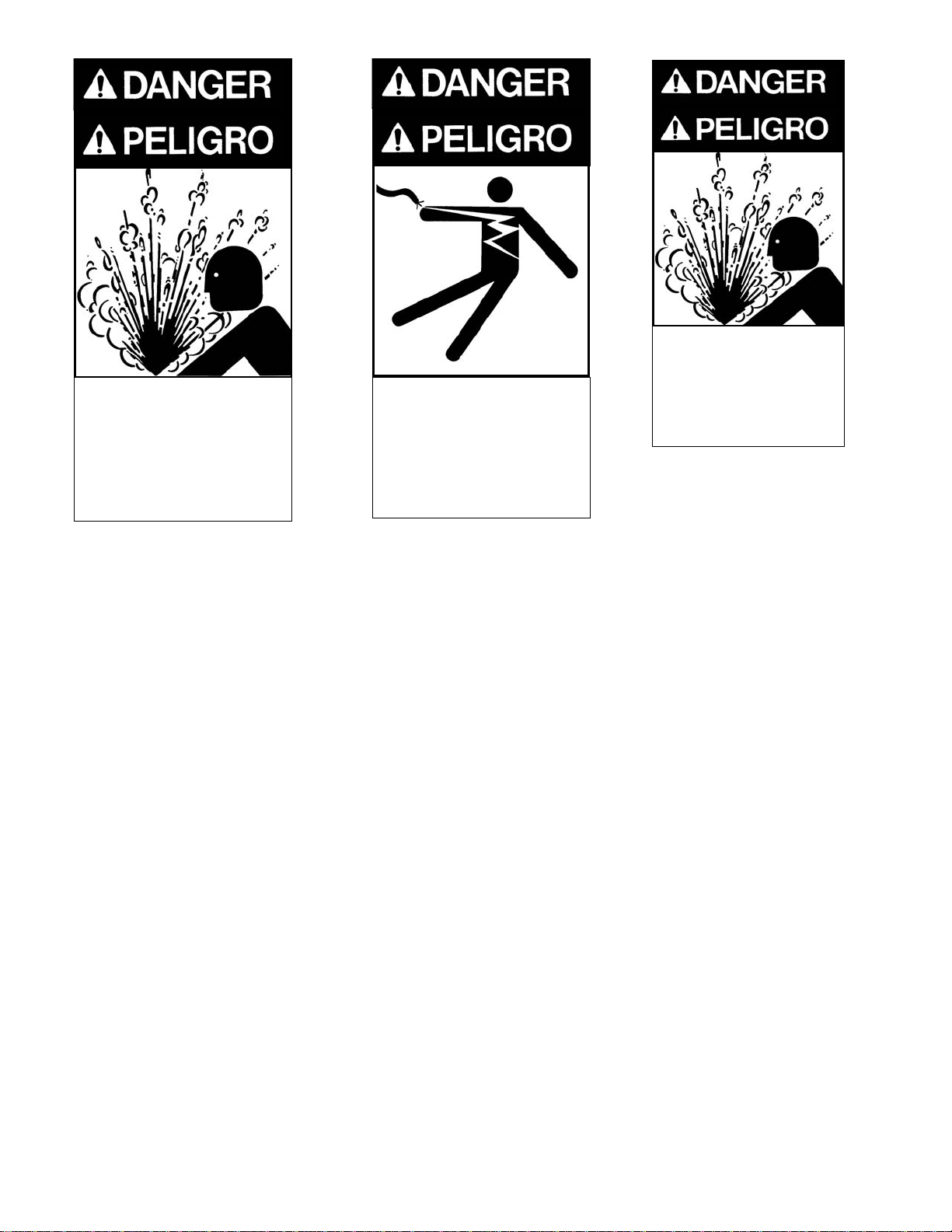
“WARNING” is used to indicate
a hazardous situation which
has some probability of death
or severe injury. Warning
should not be considered for
property damage accidents
unless personal injury risk is
present.
“NOTICE” is used to indicate a
statement of company policy
as the message relates directly
or indirectly to the safety of
personnel or protection of
property. Notice should not be
associated directly with a
hazard or hazardous situation
and must not be used in place
of “DANGER,” “WARNING,” or
“CAUTION.”
“CAUTION” is used to indicate
a hazardous situation which
may result in minor or
moderate injury.
NOTICE
CAUTION
NOTICE
WARNING
OSHA
Heading Descriptions
The user of any air dryer manufactured by ZEKS Compressed Air Solutions, is hereby
warned that failure to follow the above Safety and Operation Precautions may result
in personal injury or equipment damage. However, ZEKS Compressed Air Solutions
does not state as fact, nor does it mean to imply, that the preceding list of Safety and
Operating Precautions is all inclusive, and further, that the observance of this list will
prevent all personal injury or equipment damage.

6
Air Under Pressure Will Cause
Injury, Death Or Property Damage.
•Do Not Exceed Pressure Rating.
•Relieve Press. Before Servicing.
•Do Not Modify/Repair/Rework
ASME Coded Pressure Vessels
As Insurance Rating Affected.
! READ INSTRUCTION MANUAL !
HIGH VOLTAGE Can Cause Severe
Injury Or Death.
•Some circuits may be energized
when switch is off.
•Disconnect and lockout ALL
power sources before servicing.
! READ INSTRUCTION MANUAL !
Air Under Pressure Will Cause
Injury, Death
Or Property Damage
•
Relieve Press. Before Servicing.
•
Condensate Drain Discharges
Under Pressure.
•
Drain Requires Periodic
Cleaning (Service).
! READ INSTRUCTION
MANUAL !
L'air sous pression causera
des blessures graves, des
dégats matériels et peut
même entrainer la mort
Ne pas excéder le taux de
pression
Relâcher la pression avant
la mise en service de
l'appareil
Ne pas modifier/réparer ou
retravailler
Le taux de pression des
vaisseaux est conforme
aux recommendations de l'
ASME ( American Society
of Mechanical Engineers)
et peut être vérifié lors d'un
controle.
LIRE LE MANUEL
D'INSTRUCTIONS!
La haute tension peut
entrainer des blessures
graves ou même la mort
· Certains circuits peuvent
être chargés lorsque l'inter-
rupteur est en position
"fermé" (off)
· Déconnecter et vérouiller
TOUTES les sources d'élec-
tricité avant la mise en
service de l'appareil
LIRE LE MANUEL
D'INSTRUCTIONS!
L'air sous pression
causera des
blessures graves,
des dégats matériels
ou même la mort
Relâcher la pression
avant la mise en
service de l'appareil
Condenser les
tuyaux de décharges
sous pression
Les tuyaux doivent
être nettoyés
régulièrement
(service)
LIRE LE MANUEL
D'INSTRUCTIONS

7
Removing fuses will not
disconnect power from
dryer. Always disconnect
power from ALL sources
before performing service.
! READ INSTRUCTION MANUAL !
WARNING
ATTENTION !
Retirer les fusibles ne déconnectera pas
l'électricité de l'appareil
TOUJOURS déconnecter toutes les sources
d'électricité avant la mise en marche de
l'appareil
LIRE LE MANUEL D'INSTRUCTIONS!

6. PRINCIPLES OF OPERATION
6.1 INTRODUCTION
ZEKS’ HeatSink™ dryers remove moisture from compressed air by cooling the air
temperature to between 34°F and 38°F (1°C - 3°C). This causes vapors to condense
into liquid droplets which can then be easily removed from the air. The major systems
of the dryer which contribute to its operation are the Air System, the Moisture Removal
System, the Refrigeration System, the Thermal Mass Circulating System and the
Controls. The following paragraphs describe each of the systems in greater detail.
6.2 AIR SYSTEM
The air system consists of the dryer components which are in contact with the
compressed air. Referring to Figure 1 and following the bold “AIR FLOW,” hot saturated
air from the compressor enters the precooler/reheater where the air temperature is
reduced prior to entering the chiller by the cool air exiting the air/moisture separator.
This precooling allows for the use of a smaller refrigeration system. The air then goes
into the chiller section where it is further cooled to the desired dew point by a thermal
mass fluid. The temperature of the thermal mass fluid is maintained by the refrigera-
tion circuit and controls. The air continues to the separator where moisture is
removed, thereby, allowing the cool, dry air to return back to the precooler/reheater to
be heated by the incoming moist hot air. The air exiting the “reheater” portion of the
dryer should be approximately 15°F - 20°F lower than the inlet air temperature based
on standard conditions at full rated flow. ZEKS offers a Cold Mist Eliminator option
on all 200-400 G-Series dryers. This filter, located after the dryer’s separator,
coalesces moisture at the coldest point in the system for maximum efficiency. A
pressure differential gauge, visible from the side of the dryer, indicates the pressure
drop through the element.
8
FLOW DIAGRAM
FIGURE 1

9
ZEKS recommends changing the element in the Cold Mist Eliminator (ZEKS P/N
683532) at 6 psid. Access to the element is gained by removing the top panel of the
dryer and removing the flange bolts from the element housing. After replacement of
the filter element, reinstall flange and flange bolts and reattach dryer top panel.
6.3 MOISTURE REMOVAL SYSTEM
Liquid droplets are removed from the air stream in the separator. As the air and
liquid mixture passes through the separator it spins, slows down and then changes
direction. This causes the condensate to fall out of the air stream and collect in the
bottom of the separator. The collected liquid is removed from the separator by a
solenoid valve. The solenoid valve is controlled by the microprocessor controller as
described in Section 6.6. For adjustment please note the following:
• To obtain the optimum time values for operation of the solenoid drain valve, set
the OFF-time to 5 minutes and the ON-time to 5 seconds via the controller.
• After running the unit under full rated flow for approximately 30 minutes, verify that
when the solenoid drain opens, all of the accumulated liquid is discharged followed
by a short burst of air.
• If a small amount of liquid and a large amount of air is discharged, decrease the
ON-time setting or increase the OFF-time setting. If only liquid and no air
discharges, increase the ON-time setting or decrease the OFF-time setting.
• The ON/OFF time settings will vary according to seasonal operating conditions.
During the summer when more moisture is present in the air system a shorter
ON-time is required to increase the valve opening frequency. A longer valve
OFF-time may be used during winter months when moisture levels are lower.
On units equipped with the optional Cold Mist Eliminator, a timed electric drain is
used to remove liquid droplets from the Cold Mist Eliminator. For adjustment please
note the following:
...• To obtain the optimum time values for operation of the electric drain valve, set the
OFF-time adjustment knob to 5 minutes and the ON-time adjustment knob to 10
seconds.
...• After running the unit under full rated flow for approximately 30 minutes, verify that
when the electric drain opens, all of the accumulated liquid is discharged followed
by a short burst of air.
...• If a small amount of liquid and a large amount of air is discharged, decrease the
ON-time setting or increase the OFF-time setting. If only liquid and no air
discharges, increase the ON-time setting or decrease the OFF-time setting.

10
6.4 REFRIGERATION SYSTEM
The Refrigeration System consists of all the components which handle R-404A. This
is a hermetically sealed closed-loop system. Referring to Figure 1 and following the
phantom “REFRIG(R-404A) FLOW,” refrigerant is shown leaving the evaporator section
where, in the process of removing heat, it is changed from a low pressure liquid into
a low pressure gas. This gas enters the suction side of the compressor where it is
compressed into a high pressure gas. The high pressure gas is cooled in the
condenser section until it becomes a high pressure liquid. It then goes through a
permanent filter dryer that ensures the refrigeration system is free of contaminants.
A small diameter capillary tube (expansion valve on water-cooled dryers) meters the
refrigerant for introduction into the evaporator. The refrigerant pressure is reduced
upon entering the evaporator where as it evaporates, heat is removed from the
thermal mass fluid.
6.5 THERMAL MASS CIRCULATING SYSTEM
The thermal mass fluid in a ZEKS HeatSink™ dryer is continuously circulated in a
closed pump loop system. Referring to Figure 1 and following the dashed “THERMAL
FLUID” line, the heat is removed from the fluid in the evaporator by the refrigeration
system. The thermal mass reservoir is sized to minimize refrigeration cycles during
reduced air load periods. The thermal mass fluid is pulled from the bottom of the
reservoir and pumped through the chiller, removing heat from the air, and is then
returned to the evaporator. The pump utilized on a ZEKS HeatSink™ dryer is a
maintenance-free, quiet cartridge circulator pump similar to those used in residential
water systems. While the refrigeration system cycles on and off based on loading
conditions, the circulating pump runs continuously to maintain flow through the chiller
at all times. Note that when the power switch is set to the off position, the circulating
pump will not operate.

11
6.6 CONTROLS
The ZEKS HeatSink™ dryer incorporates automatic controls for proper operation.
The standard microprocessor is the Compustat Controller.
NOTE: For dryers equipped with the optional DPC Plus Controller, refer to the DPC
Supplement that accompanies this Technical Manual for specific instruction on
operating the HeatSink™ dryer with the DPC Plus Controller.
The thermal mass fluid temperature is maintained by the microprocessor that
monitors the temperature and cycles the refrigeration system in response to varying
air flow and temperature. Upon an increase in the temperature of the thermal mass
fluid, the compressor is cycled on. When the fluid is cooled to its control set point,
the compressor is cycled off. The thermal mass fluid functions as a thermal storage
mass in the HeatSink™ dryer.
A low pressure cut out (LPCO) switch is provided for all HSG series dryers. This
switch is factory set to open at 30 psig. If the refrigerant suction pressure draws
below 30 psig, the LPCO opens to shut off the refrigerant compressor. Once the
switch has opened, it will prevent the compressor from running until the suction
pressure rises above 60 psig and the LPCO has been manually reset.
When the optional gauge package is included, inlet air temperature, outlet air
pressure, refrigerant suction and discharge pressure gauges are supplied.
1) Refrigerant discharge gauge monitors the pressure of the refrigerant gas exiting the
compressor. This reading will vary dependent upon condenser type as indicated below:
• Air Cooled condensers with ambient temperatures between 80°F and 100°F: the
refrigerant discharge gauge should read between 275 - 350 psig.
• Water cooled condensers utilize a water regulating valve (See Figure 2):
the water regulating valve comes pre-adjusted from the factory at 250 psig
discharge pressure.
ADJUSTMENT SCREW
FIGURE 2
WATER REGULATING VALVE
Drawing 600562

12
COMPUSTAT CONTROLLER BUTTONS
• ON/OFF
Pressing this button will start or stop the unit. It toggles the unit between on and off.
• EXCHANGER SET
Press this button to adjust the exchanger temperature control set point. The
refrigeration system will cycle on 1.5°F above the set point and cycle off 1.5°F
below the set point.
• DRAIN OPEN
This button controls the length of time, in seconds, the drain will stay open.
• % SAVINGS
Press this button to review how much time the compressor has been running while
the unit has been energized in the DRYER ON condition. This may be reset by
holding down the button for ten seconds.
• When the refrigeration system is running, the suction pressure will pull down
between 50 and 60 psig, depending on load and ambient conditions. After the
thermal mass fluid has been cooled and the refrigeration system is cycled off,
the system pressure will equalize with a gauge reading typically between 80
and 150 psig - depending on ambient temperature.
All water cooled units come with a high pressure cut out (HPCO) switch. This
switch is set to open at 320 psig and close at 270 psig.
To compensate for variation in water temperature, it may be necessary to adjust the
water regulating valve to maintain a 250 psig discharge pressure. Adjustment can
be done by rotating the adjusting screw counterclockwise for an increase in
discharge pressure. For conditions where low water temperature and/or high water
pressure are expected it is advisable to install a water pressure regulator ahead of
the condenser.
2) Outlet air pressure gauge monitors the exiting compressed air pressure. During
normal operation, the outlet air pressure should be within 3 psig of the compressed
air entering the dryer.
3) Inlet air temperature gauge monitors the compressed air temperature entering the dryer.
During normal dryer operation, the temperature reading should be 100°F or lower.

13
• ALARM RESET
Press this button to open the optional relay for the remote alarm. This does not
correct the alarm condition which is indicated by the flashing alarm light.
• DRAIN TEST
Press this button to verify drain operation.
• °F/°C
This button selects Fahrenheit or Celsius temperature scale for the display.
• UP/DOWN ARROWS
These buttons raise or lower the exchanger temperature and increase or
decrease the drain open and drain close settings.
COMPUSTAT CONTROLLER LIGHTS
• SYSTEM ENERGIZED
Indicates when power is applied to unit.
• DRYER ON
Illuminated when the ON/OFF switch has been pressed to place the unit in
operation. The refrigerant system may start at any time when the light is on.
• REFRIGERATION COMPRESSOR ON
This light comes on when the refrigeration compressor is operating.
• DRAIN OPEN
This light comes on when power is applied to open the timed solenoid drain.
• DEG. F
Illuminated when readings are in degrees Fahrenheit.
• DEG. C
Illuminated when readings are in degrees Celsius.
• HIGH TEMP. ALARM
When this light is on, it indicates that the exchanger temperature has risen to
12°F or 7°C above the exchanger temperature set point.
• LOW TEMP. ALARM
When this light is on, it indicates that the exchanger temperature has dropped
below 29°F or -2°C. This condition stops the compressor and it will not restart
until the temperature has risen two degrees above exchanger set point.
COMPUSTAT CONTROLLER DISPLAY
The display is composed of two 3/4” letters. These are used to display tempertures
in the 15°F to 99°F range. Temperatures outside this range will be displayed as
“EE”. The display also informs you of fault or delay conditions.
• PF indicates a probe failure. This is usually caused by a probe being unplugged,
damage to the probe lead or a defective probe.
• cd indicates that the refrigerant compressor will not start until the end of a three
(3) minute safety delay. The display of “cd” is immediately followed by the
number of minutes left in the delay.

14
Failure to comply to the above instructions may result in equipment malfunction
and will void warranty.
NOTICE
Always use a backup wrench when making any threaded connection to the dryer.
Failure to use a backup wrench may result in damaged tubing and components
internal to the cabinet.
NOTICE
7. INSTALLATION AND INITIAL START-UP
7.1 LOCATION AND MOUNTING
The dryer should not be located in an area where ambient temperature is likely
to exceed 113°F (45°C) or be less than 50°F (10°C). The dryer must be located in
an area that provides sufficient clearance from walls and other adjoining equipment
to allow easy access for servicing and maintenance requirements. A minimum of
30 inches is required to allow free flow of air to the condenser inlet and clearance
for servicing the dryer.
On installations with a relatively steady flow rate, the dryer is normally connected
after the air receiver. If loads fluctuate widely, the dryer should be positioned ahead
of the receiver and sufficient storage capacity downstream is necessary to prevent
excessive air flow through the dryer.
When installed after any compressor that causes significant vibration or air pulsation,
such as reciprocating compressors, proper vibration isolation and pulsation
dampening devices should be added to protect the dryer.
7.2 PIPING AND VALVES
Install piping, fittings and accessories as required for specific site conditions and
requirements. Figure 3 indicates a typical piping arrangement for a refrigerated
dryer, including dryer and filter bypasses. This figure can be used as a guide for
valve and accessory placement in the system.
WEATHERPROOF PACKAGE (OPTIONAL)
Dryers equipped with the optional Weatherproof Package are designed to operate in
ambient conditions as low as 35°F. This package incorporates a fan cycling switch
that operates the refrigeration system at optimal condensing temperatures. The fan
switch controls the condensing temperature by cycling the fan based on refrigerant
discharge pressure. When the unit reaches 275 psig, the fan cycling switch will run
the fan until the discharge pressure is reduced to 195 psig.
Dryers equipped with the weatherproof package are not intended for use below 35°F.
NOTICE

FIGURE 3
TYPICAL PIPING ARRANGEMENT
AIR
DRYER
OIL
SEPARATOR
DRAIN
VALVE
CHECK
VALVE
CHECK
VALVE
CHECK
VALVE
DRAIN
VALVE
CHECK
VALVE
PREFILTER
B
A
CAIR OUT
AIR IN
UNIT AS DELIVERED
OPTIONAL ACCESSORY ITEMS
NOTE: DRAIN TUBE MUST NOT RISE OR BE CONNECTED TO
EXCESSIVELY LONG PIPE WHICH MAY CREATE BACK PRESSURE
A CONNECTION TO OPEN FLOOR DRAIN IS REQUIRED
DE
7.4 ELECTRICAL CONNECTION
Equipment is available in various electrical configurations. All customer power
connections can be made at the terminal connections located in the Customer
Electrical Connection Box on the rear of the dryer. (Refer to General Arrangement
and appropriate Wiring Diagrams.)
A suitable fused disconnect switch or circuit breaker, in accordance with national and
local code requirements, is recommended for all ZEKS equipment. Refer to Section
13 for voltage requirements and load.
15
ZEKS 200 - 400 HSG models come with a drain isolation valve (D) factory installed.
The isolation valve permits maintenance of the automatic drain without isolating air
flow to the dryer. To operate dryer, all valves shown in Figure 3 are to be closed
except valves (B), (C) and (D). Valve (A) is used for bypass purposes and valve
(E) is for test and manual drain purposes.
7.3 FILTRATION
To protect the air dryer from gross contamination associated with compressor oil
and debris and ensure maximum dryer performance, a prefilter is recommended.
Prefilters and afterfilters sized to your drying application can be provided by ZEKS
and are available factory installed. Call your local distributor to select the filter that
best suits your filtration requirements. In addition to air filtration, condensate discharge
oil/water separators are also available to address stringent EPA regulations.

16
Never wire directly, or connect any additional wires, to the compressor
junction box. This will cause severe system malfunction.
CAUTION
7.5 INITIAL START-UP
• Turn customer fused disconnect to the “ON” position. The dryer “SYSTEM
ENERGIZED” light will illuminate.
• After the 3 minute safety delay, depress the dryer “ON/OFF” button.
• The “DRYER ON” light will illuminate.
• Provided the chiller temperature is above the Chiller Temperature Set Point, the
“REFRIG ON” light will illuminate and refrigeration system will operate.
• The “HIGH TEMP ALARM” light will illuminate upon start-up and remain that way
until the thermal mass fluid in the chiller reaches 50°F. After the temperature is
reduced below 50°F, the “HIGH TEMP ALARM” light will go out.
• After the refrigeration system shuts off, air flow may be introduced to the dryer.
• Drain settings should be checked as described in Section 6.3.
For water cooled models, the water valve must be manually opened to
ensure that the condenser is full of water prior to start-up.
NOTICE
Exchanger temperature should never be set lower than 35° as system
malfunction could occur.
NOTICE
Slowly pressurize dryer after start-up
CAUTION
After installation or a prolonged shutdown, start the dryer with no air load (no air
flow). This enables the dryer to reach its proper operating temperature in the
shortest time possible (typically within 30 minutes).
NOTICE

8.0 SCHEDULED MAINTENANCE
8.1 INTRODUCTION
ZEKS HeatSink™ refrigerated air dryers require little maintenance. These dryers
utilize hermetically sealed compressors which do not require any lubrication. Fan
motors require lubrication at both oil ports every six months. ZEKS recommends
component inspection and service at regular intervals to obtain maximum performance
from your dryer.
8.2 REFRIGERATION CONDENSER
ZEKS dryers can be equipped with an optional ambient air filter that is designed to
protect the condenser from the accumulation of dirt and debris. For proper operation,
it is imperative that this filter be inspected and cleaned on a regular basis. For
applications where excessive dirt, dust or debris is encountered, frequent inspection
and cleaning may be required. Annual replacement of the filter is recommended.
17
8.3 CONDENSATE DISCHARGE SYSTEM
On a minimum of a monthly basis, operation of the automatic drain should be
checked. The drain should be removed and cleaned as well to ensure no debris
from the system is trapped inside the strainer. Figure 4 illustrates the drain assembly.
To clean the drain, turn the Isolation Valve to the off position. Be sure the valve is
depressurized. Carefully remove the Strainer End Cap and remove the Strainer.
Clean the Strainer and remove any debris that is evident in the valve. Replace the
Strainer and reinstall the Strainer End Cap. Carefully open the isolation valve and
inspect the Strainer End Cap for leaks. Tighten as required.
If your dryer is installed without a drain isolation valve (filter stop), failure to
depressurize the dryer may result in serious injury. Do not remove the drain valve
without depressurizing the unit.
WARNING

CLEANING INSTRUCTIONS - SOLENOID DRAIN VALVE
• Be sure dryer is depressurized or
...isolation valve is closed.
• Disconnect drain body from filter stop.
• Loosen connector screw to allow the
electrical connector assembly to be
removed from the D.I.N. unit solenoid.
• Remove retainer nut and separate the
valve body from the D.I.N. unit solenoid.
• Unthread the plunger tube assembly in a
counter-clockwise direction until plunger
separates from valve body.
• Clean beveled washer, thread gasket,
spring assembly and strainer with soap
and water. Do NOT use solvents of any
kind, as failure to the seals will occur.
Be especially careful to clean the center
brass orifice and the rubber gasket orifice
on the orifice cup with a straight pin.
• Reassemble all drain components after the drain has been cleaned and inspected.
Reposition the orifice hole on the rubber gasket of the orifice cup in the line and
closest to the arrow indicated on the valve body.
• Reassemble valve and install in reverse order as described above.
SOLENOID VALVE DETAIL
18
FIGURE 4
DRAIN DETAIL
DRAWING 737486 B

19
9.2 PROBLEM / ACTION GUIDE
PROBLEM
Moisture down stream
SYMPTOM(S)
Dryer is properly
cooling air stream
(Check Exch. Temp on
controller)
Inlet and outlet
temperatures are the
same.
POSSIBLE CAUSE
Drain failure or timer
adjustment is required
Excessive flow
Dryer by-pass valve not
closed
No power to the dryer
CORRECTIVE ACTION
Depress “Drain Test” button - if
drain valve operates, then adjust
timing (See Section 6.3)
Depress “Drain Test” button - if
“Drain Open Light” comes on but
valve does not open, ensure wiring
connections are secure and power
is being applied to the solenoid coil.
If valve continues not to open,
clean as described in Section 8.3.
Depress “Drain Test” button - if
“Drain Open Light” does not come
on, contact distributor.
Check inlet and outlet pressures
and system design capacity.
Correct cause of excessive flow.
Close by-pass valve
Check power supply and
fuses/circuit breakers
An air dryer always operates under pressure. Any maintenance procedure that
involves disassembly of pipe fittings, valves or any other components requires the
dryer be isolated from the compressed air stream and fully depressurized.
Prior to working on the unit, make sure that all circuit breakers or disconnected
switches are tagged “Out of Service.”
9. TROUBLESHOOTING
9.1 INTRODUCTION
ZEKS HeatSink™ dryers are designed for reliable, trouble-free operation. In the
event of any dryer malfunction, the guide below has been developed to facilitate
problem identification and corrective actions.
WARNING
WARNING
This manual suits for next models
4
Table of contents
Other ZEKS Dehumidifier manuals
Popular Dehumidifier manuals by other brands

Horizon Fitness
Horizon Fitness Galaxy Installation and operation manual

Dantherm
Dantherm AD 240B Service manual

ETI
ETI NETCOM ADH Assembly Replacement Procedure

Electrolux
Electrolux EXD25DN3W user manual

POWERPYE ELECTRONICS
POWERPYE ELECTRONICS PPYPDZ12A WIFI Instruction manual and warranty card

INVENTOR
INVENTOR PR1-ION21L user manual