manuals.online logo
Brands
  1. Home
  2. •
  3. Brands
  4. •
  5. Zephyr
  6. •
  7. Industrial Equipment
  8. •
  9. Zephyr ZGS-12000-1 User manual

Zephyr ZGS-12000-1 User manual

ZOM-12000-1 rev 0
Page1 of 15
Fixed Hoist Test Facility (FHTF)
ZGS-12000-1
ZOM-12000-1 rev 0
Page2 of 15
Fixed Hoist Test Facility (FHTF)
Purpose: The FHTF when used in conjunction with the Mobile Ground Support
Equipment (MGSE) provides the capability to operate the hydraulic rescue hoist off of
the aircraft in order to perform intermediate level maintenance and troubleshooting.
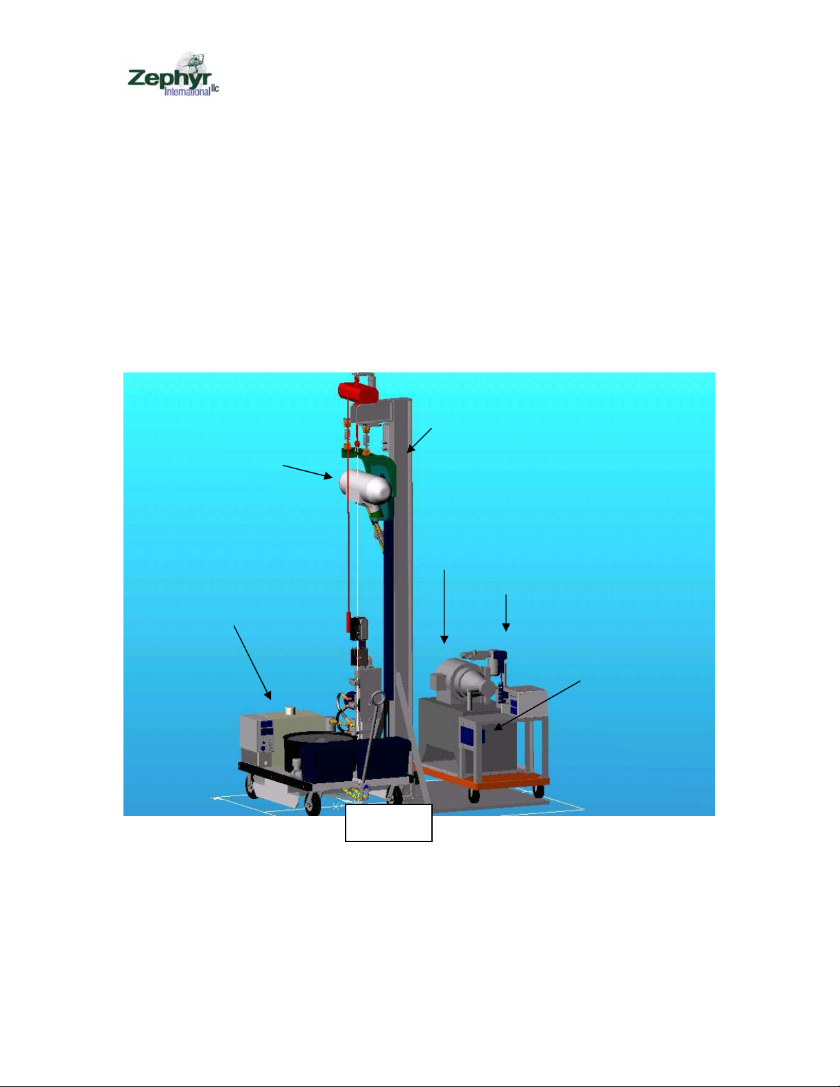
Description of FHTF: The FHTF consists of an upright structure, an upper weldment
assembly, a hanging hoist mount, a chain hoist for raising and lowering the unit under
test (UUT), a load weigh system, a hydraulic power supply, a 28 volt power supply, a
differential pressure measuring system and a flow measuring system. The hydraulic
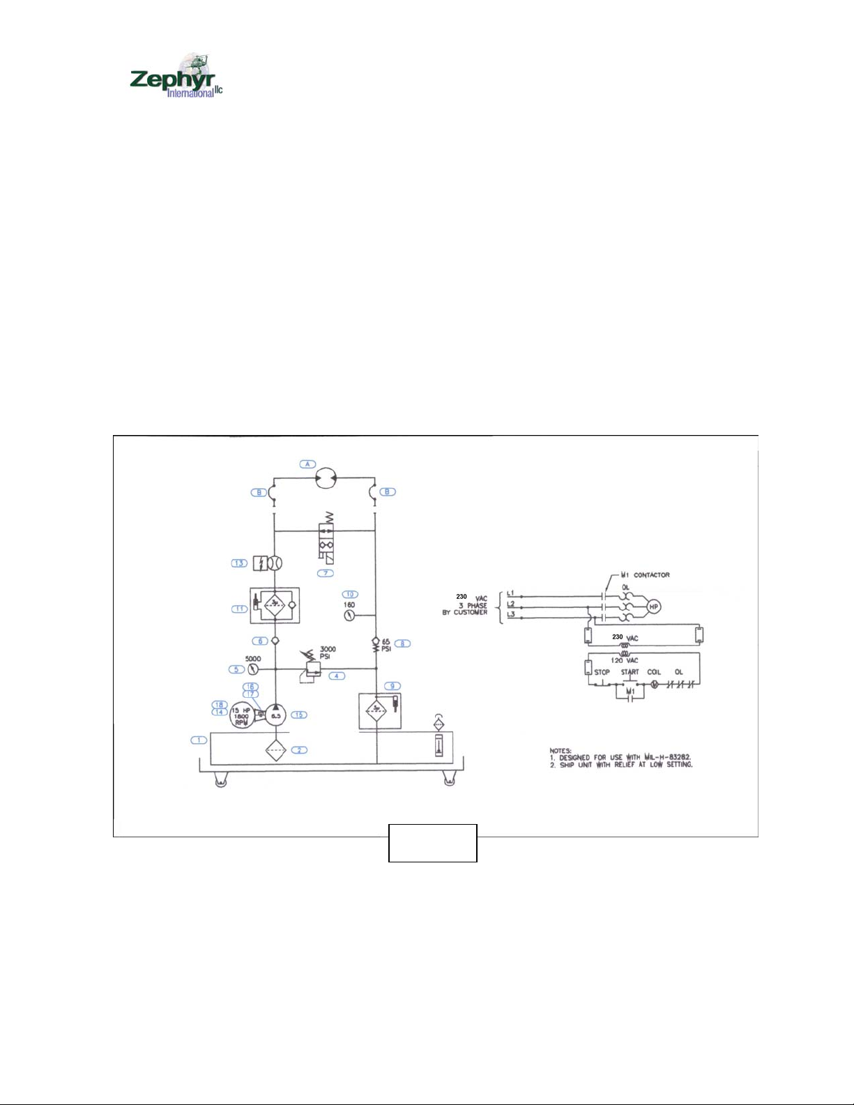
supply is powered by a 230 volt 3 phase electric motor, and two boost transformers are
used to boost the facility’s 208 volts 3 phase power to 230 volts.
The UUT control signals are provided by a government supplied controller and pendant.
Theory of Operation: The FHTF provides 3000 psi hydraulic power at a maximum 6.5
gallons per minute. The hydraulic supply includes a shut off valve to bypass the flow
when the hoist is not running. The hydraulic system uses MIL-H-83282 hydraulic fluid
and includes a high pressure filter rated at 3 microns and a low pressure filter rated at 3
microns.
The upright structure is equipped with a chain hoist to raise the UUT up to the top of the
structure where it is attached to two load cells. The two load cells provide signals to a
load cell summing box where the signals are summed and sent to a display. The load
readout can be set to zero to tare the readout with no load applied to the rescue hoist
hook.
The wire rope tensile load is provided by the MGSE. The MGSE provides the capability
to extend the wire rope under approximately 150 lbs. maximum load, and provides the
capability to retract the wire rope under approximately 600 lbs. maximum load.
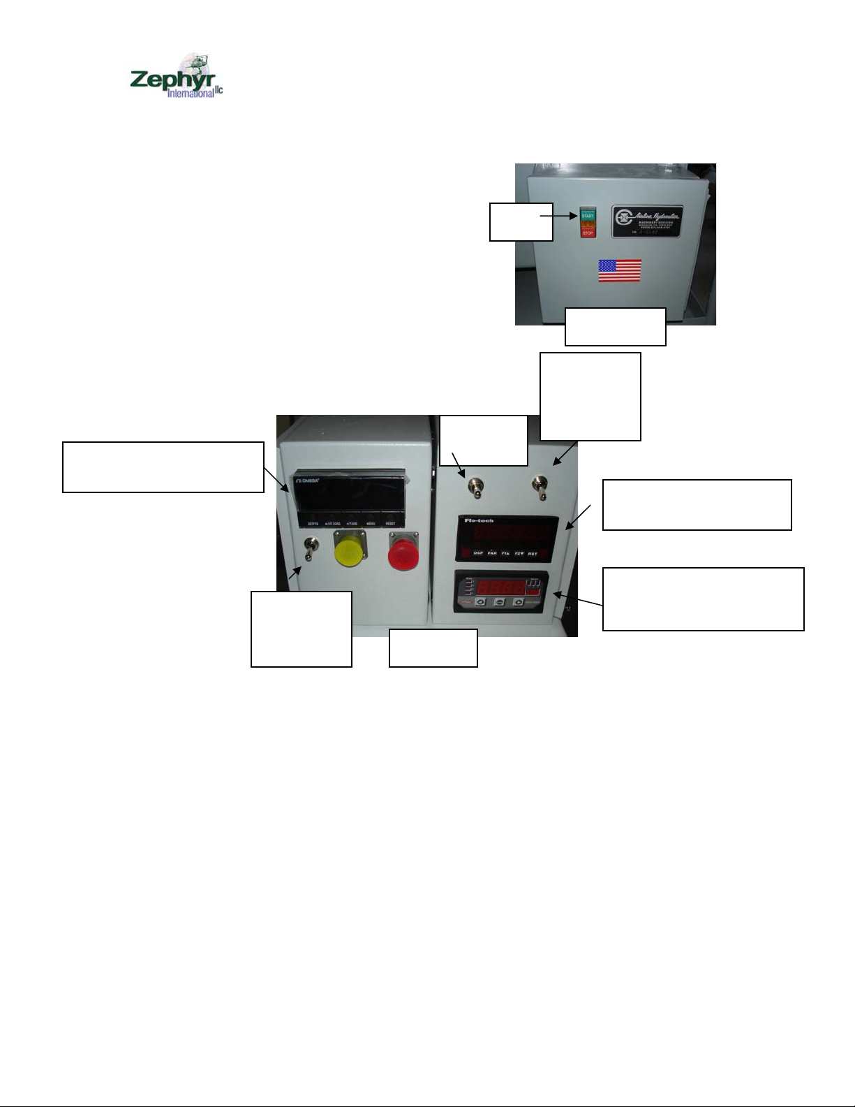
The hydraulic system includes two pressure transducers in the pressure and return lines.
The transducers provide signals to a microprocessor that displays the differential pressure
the UUT requires to lift the load. The hydraulic system is also equipped with a turbine
flow meter that provides a signal to the flow display.
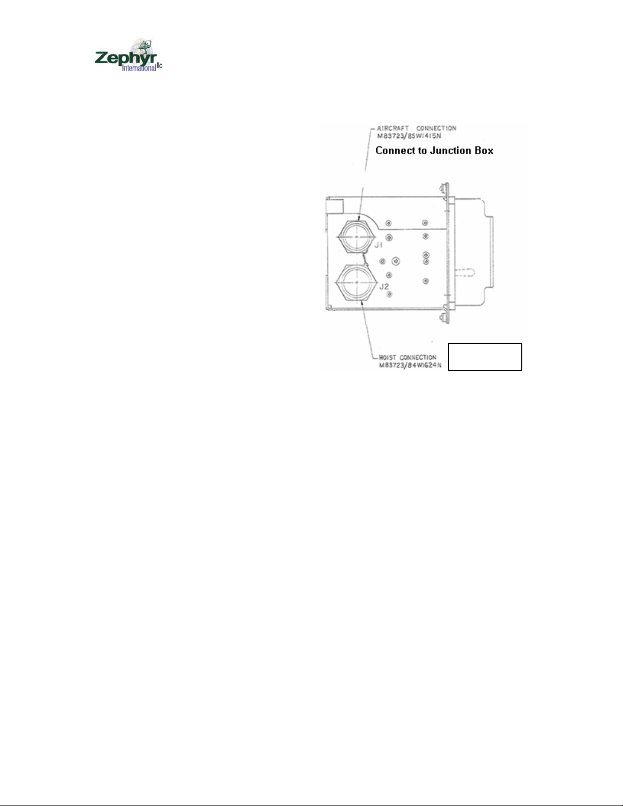
The 28 volts required to control the UUT hydraulic control system is provided by a
power supply mounted in the junction box. The control pendant is mounted via its
connector directly to the front of the junction box, and the electrical control box is
mounted to the front of the test table. Two electrical cables couple the control box to the
junction box and the electrical controller to the hoist.
Electrical loads:
208 volts 3 phase is approximately 16 KVA requires a 125 amp line fuse
120 volts single phase approximately 15 amps
ZOM-12000-1 rev 0
Page3 of 15
UUT operating criteria: The UUT is rated for 600 lbs and 215 feet per minute when
powered with a maximum of 2650 psi differential pressure and a flow of 5.5 gallons per
minute flow.
FHTF Limitations:
The FHTF is not intended to provide the capability to perform a complete acceptance test
as per the OEMs requirements but to allow the maintenance personnel to perform checks
of the system performance, set the hoist’s limit switches, adjust the levelwind, adjust the
flow control and replace and season the wire rope before the UUT is mounted onto the
aircraft; thus minimizing aircraft down time and flight time required if those procedures
were carried out on the aircraft.
System Picture:
Installation Requirements:
The hydraulic supply must be blocked to sit firmly on the Upright assembly base.
The location should be out of the way of aircraft or equipment movement.
The location should be as close as possible to the 208 VAC electrical disconnect box.
Upright Assembly
Hydraulic Supply
Pendant
Electrical
control box
UUT
MGSE
Figure 1
ZOM-12000-1 rev 0
Page4 of 15
The location should be located so that when the system is being used, personnel who are
using it can not be injured from other activities in the hanger that they will not be aware
of because of their focus on the UUT and MHGSE.
System Floor Plan:
Figure 2
ZOM-12000-1 rev 0
Page5 of 15
Figure 3
Figure 4
Figure 5
Mount controller here
Attach control box cable
ZGS-12129-1 here
Attach pendant cable
here
Junctio
nBox
Installing the UUT
To install the UUT the hanging hoist mount must is
lowered by raising the hoist mount with the chain hoist
hand control just enough to allow removing the pins from
the lower load cell clevis. Remove the pins and then
lower the hanging mount to the lower position as shown
in figure 3.
Install the UUT onto the post mount and install two ¼
inch pins.
Using the hand control raise the hanging hoist mount up to reattach the
two clevis pins, then lower the chain hoist to apply all the
weight to the load cells.
Attach the hydraulic adapter fittings to the input block as
shown in figure 4. The input or pressure line is the # 6
fitting and the return or tank line is the #8 fitting.
Attach the UUT electrical cable ZGS-12128-1 to the J1
connector. The J2 connector is for the AC power to run the
hoist fan, and the fan is not required when running the hoist
on the FHTF.
Mount the electrical control box in the opening on the
control table and attach the pendant and the control box
electrical cable as shown in figure 5.
Attach the control box cable and the UUT electrical cable as shown in figure 6.

Other Zephyr Industrial Equipment manuals

Zephyr ZGS-11000-2 v2 User manual

Zephyr

Zephyr ZGS-11000-2 v2 User manual

Zephyr ZGS-12000-7 User manual

Zephyr

Zephyr ZGS-12000-7 User manual

Zephyr ZGS-12000-4 User manual

Zephyr

Zephyr ZGS-12000-4 User manual

Zephyr ZOM-12000-9v1 User manual

Zephyr

Zephyr ZOM-12000-9v1 User manual

Popular Industrial Equipment manuals by other brands

ABB +Q957 user manual

ABB

ABB +Q957 user manual

G.B.C BASIC EDGE 50 instruction manual

G.B.C

G.B.C BASIC EDGE 50 instruction manual

Tronair Batpak 11-6602-1000 Operation & service manual

Tronair

Tronair Batpak 11-6602-1000 Operation & service manual

Pilz PNOZ mi2p Operation manual

Pilz

Pilz PNOZ mi2p Operation manual

Clemco Zero BNP 6012 manual

Clemco

Clemco Zero BNP 6012 manual

Erskine Attachments V-Plow Operator's manual

Erskine Attachments

Erskine Attachments V-Plow Operator's manual

ABB HT610965 Operation manual

ABB

ABB HT610965 Operation manual

Morra MH 540 user manual

Morra

Morra MH 540 user manual

Eaton S090ST manual

Eaton

Eaton S090ST manual

GRIGGIO G 240 P4 instructions

GRIGGIO

GRIGGIO G 240 P4 instructions

Nexen AIR CHAMP HT45 user manual

Nexen

Nexen AIR CHAMP HT45 user manual

WTE V5 installation manual

WTE

WTE V5 installation manual

ABB HT845232 Operation manual

ABB

ABB HT845232 Operation manual

SMC Networks CJP Series Operation manual

SMC Networks

SMC Networks CJP Series Operation manual

JohnDow Industries JDI-AFT58 Operator's manual

JohnDow Industries

JohnDow Industries JDI-AFT58 Operator's manual

IMB MB9016A instruction manual

IMB

IMB MB9016A instruction manual

Clarke CUMB1 Assembly & operating instructions

Clarke

Clarke CUMB1 Assembly & operating instructions

amiad Arkal Spin Klin 2 user guide

amiad

amiad Arkal Spin Klin 2 user guide

manuals.online logo
manuals.online logoBrands
  • About & Mission
  • Contact us
  • Privacy Policy
  • Terms and Conditions

Copyright 2025 Manuals.Online. All Rights Reserved.