Zephyr ZOM-12000-9v1 User manual

ZOM-12000-9v1
This manual contains proprietary information and is not to be copied or disclosed without written permission from
Zephyr International LLC.
Copyright 2002-2013 Page 1 of 24
Operation and Maintenance Manual
ZOM-12000-9v1

ZOM-12000-9v1
This manual contains proprietary information and is not to be copied or disclosed without written permission from
Zephyr International LLC.
Copyright 2002-2013 Page 2 of 24
BL-27100 BL-29900 BL-10300
ZGS-12000-9v1 Fixed Hoist Test Facility
1) Purpose
a. The purpose of the Fixed Hoist Test Facility (FHTF) is to allow the
operation, maintenance, and training of the operation and maintenance of
rescue hoists in use by the 160th SOAR without the need of an aircraft.
b. The FHTF works in conjunction with the ZGS-10000-5-2 mobile take up
assembly.
2) Scope
a. The FHTF provides provisions for the mechanical and electrical
attachments of three different rescue hoists.
i. BL-29900-xx
ii. BL-27100-xx
iii. BL-10300-151
b. The FHTF is intended to be used in conjunction with the ZGS-10000-5-2
Mobile Rescue Hoist Ground Equipment (RHGSE). The RHGSE has
been equipped with a work platform to enable working on the hoist while
in the operating position. This allows closer inspection of the hoist
mechanism, setting the limit switches and installing and removing the
rescue hoist cable.

ZOM-12000-9v1
This manual contains proprietary information and is not to be copied or disclosed without written permission from
Zephyr International LLC.
Copyright 2002-2013 Page 3 of 24
c. The combined system allows operating the rescue hoists for the purpose
of setting limit switches, verifying correct setup of the hoist mechanisms,
changing the cable, and tensioning a new cable under load.
d. The FHTF is supplied with a hydraulic power supply that has been
designed to maintain the cleanliness of the hydraulic fluid used in the
hoist in order to prevent the contamination of the hydraulic system of the
aircraft.
The hydraulic power supply provides 3000 psi pressure at 6 GPM. The
system is equipped with a high pressure filter and a low pressure filter
and self sealing quick disconnects. The high pressure filter is rated to 5
Micron (abs) and has a clogging indicator. The low pressure filter is rated
is rated to 5 micron. The system also utilizes a contamination control
breather that removes moisture from the air and therefore keeps water
out of the hydraulic fluid. The hydraulic fluid used is the same as used in
the aircraft, Mil-H-83282.
Low Pressure Filter
High Pressure Filter

ZOM-12000-9v1
This manual contains proprietary information and is not to be copied or disclosed without written permission from
Zephyr International LLC.
Copyright 2002-2013 Page 4 of 24
e. The FHTF has been supplied with an onboard 24 Volt power supply to
provide power to the Mobile RHGSE in order to allow for continual
operations without having to stop and recharge the batteries on the
Mobile RHGSE
f. The FHTF has the mounting brackets, interconnect cables and hydraulic
lines and fittings to test all the hoists it has been designed to service.

ZOM-12000-9v1
This manual contains proprietary information and is not to be copied or disclosed without written permission from
Zephyr International LLC.
Copyright 2002-2013 Page 5 of 24
3) Theory of Operation
a. The system is supplied with hoist adapters and a chain hoist that are
used to raise the hoist into position where two load cells attach and
support the weight of the hoist and adapter and the load applied by the
Mobile RHGSE.

ZOM-12000-9v1
This manual contains proprietary information and is not to be copied or disclosed without written permission from
Zephyr International LLC.
Copyright 2002-2013 Page 6 of 24
b. The system is equipped with quick disconnects and electrical connector
and cables to attach the three types of hoists. The mounting bracket
moves with the hoist mount, therefor eliminating the possibility of damage
to the cable or connectors if they are not disconnected before lowering or
raising the mount.
c. The system is equipped with a 28 volt 5 amp
power supply to provide control power to the two
control boxes that operate the BL-27100 and the
BL-29900 hoists.
d. The system includes the means to mount the
control box for the BL-27100, and the pilot
control box and the pilot control box for the
BL-29900.
28 VDC power supply is inside
the control box.

ZOM-12000-9v1
This manual contains proprietary information and is not to be copied or disclosed without written permission from
Zephyr International LLC.
Copyright 2002-2013 Page 7 of 24
e. The system is equipped with a proportional control valve and a joystick
controller to operate the BL-10300 hoist.
f. The system is equipped with a MS90362-1 receptacle to accept the plug
that delivers 115 V 3 phase 400 hz power to the BL-29900 hoist and the
BL-27100 hoist fan.

ZOM-12000-9v1
This manual contains proprietary information and is not to be copied or disclosed without written permission from
Zephyr International LLC.
Copyright 2002-2013 Page 8 of 24
g. The system is equipped with a 30 Amp 3 phase breaker to protect the
BL-29900 and the equipment wiring in the event of a hoist malfunction.
h. The system is equipped with three 2 amp circuit breakers in the event the
three phase fan on the BL-27100 is to be operated. If the fan has a
problem with one of its windings the breakers will protect the fan and the
wiring from further damage.
i. The system is equipped with an hour meter that operates when ever the
load display is on.
j. All the pins that are used to attach the various components are tethered
to the component so they are not easily lost
k. The system is also equipped with a 24 volt power supply to provide power
to the ZGS-10000-5-2 mobile take up while in use with the Fixed Hoist
Test facility.

ZOM-12000-9v1
This manual contains proprietary information and is not to be copied or disclosed without written permission from
Zephyr International LLC.
Copyright 2002-2013 Page 9 of 24
4) Operating Procedure
BL-27100
Start Up
1. Install the Hanging Hoist Mount, ZGS-12613-1 using the pins and
retaining pins
2. Install the hoist on mount using the pins and retaining pins
3. Clean hydraulic fittings thoroughly
4. Attach hydraulic lines, (Caution) Insure the return line QD is mated
completely! Failure of the heat exchanger will result if the return line QD
is not fully engaged
5. Attach Electrical harness connector
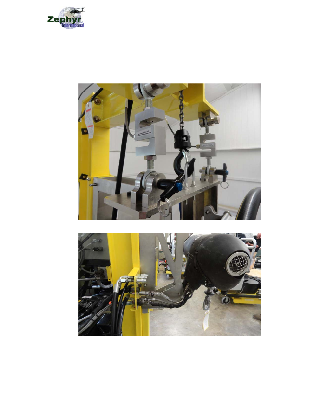
6. Raise mount into position, install pins in load cells, lower chain hoist to
apply the load to the lead cells
7. If the fan is to be tested attach the 400Hz power cable to the receptacle
8. If the fan is to be tested , turn on the 3 phase 400 hz power switch
9. Position the Zephyr GSE under hoist
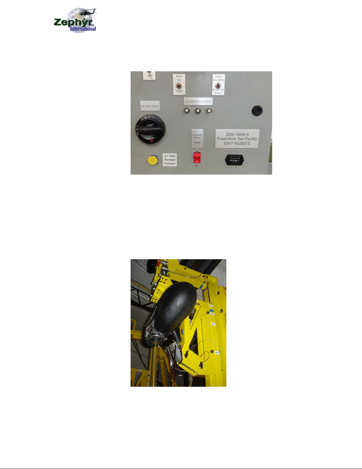
10. Activate the hoist select switch on the motor starter panel to select the
BL-27100
11. Pull out E-Stop button to turn on power
12. Press Pump Start button to start the hydraulic pump
13. Turn the Pressure switch to on, approx 3000 psi pressure should
develop on the pressure gage
14. Turn the Power switch on the control box to on, the load indicator
should illuminate
15. Activate the hoist select switch on the control box to select the BL-
27100 hoist
16. Press the Tare button on the load display to zero out the load with no
load on the cable
17. Operate the hoist using the pendant, pilot override or backup power
control, (Caution) Using the backup power control overrides the limit
switches in the hoist
18. Attach the rescue hoist cable to the Zephyr GSE and operate the hoist
in the down direction
19. Follow the operating instructions for the Zephyr GSE while running the
hoist

ZOM-12000-9v1
This manual contains proprietary information and is not to be copied or disclosed without written permission from
Zephyr International LLC.
Copyright 2002-2013 Page 10 of 24
Shut Down
20.Disconnect the rescue hoist cable from the Zephyr GSE
21.Retract the cable to full in and insure the full up limit switch activates and
the bumper compresses properly
22.Turn off the Power switch on control box
23.Turn the pressure switch to off
24.Push in E-stop button
25.Press the 3 phase 400 hz power switch to off
26.Detach the electrical harness
27.Detach the hydraulic lines
28.Raise rescue hoist mount with the chain hoist and remove the pins
29.Lower the hoist to the lowest position
30.Remove the hoist and arm from hoist mount

ZOM-12000-9v1
This manual contains proprietary information and is not to be copied or disclosed without written permission from
Zephyr International LLC.
Copyright 2002-2013 Page 11 of 24
BL-10300
Start Up
1. Install the Clevis Pin Hoist Mount, ZGS-12608-1 using the pins and
retaining pins
2. Install the BL-10300 hoist on the mount using the pins and retaining pins
3. Attach the hydraulic lines, insuring the up and down lines are attached
properly
4. Attach the electrical harness connector
5. Raise the mount into position, and install pins in load cells, lower chain
hoist to apply the load to the lead cells
6. Position the Zephyr GSE under the hoist
7. Pull out the E-Stop button to turn on power
8. Press the Pump Start button to start the hydraulic pump
9. Activate the hoist select switch on the motor starter panel to select the
BL-10300
10.Turn the Pressure switch to on, pressure should develop on the pressure
gage
11.Turn the Power switch on the control box to on, the load indicator should
illuminate
12.Press the Tare button on the load display to zero out the load with no
load on the cable
13.Pull up the locking ring on the Joystick controller and activate the hoist in
the extend direction
14.Attach the cable to the Zephyr GSE and operate the hoist in the down
direction
15.Follow the operating instructions for the Zephyr GSE while running the
hoist
Shut Down
16.Disconnect the cable from the Zephyr GSE
17.Retract the cable to full in and insure the full up limit switch activates and
the bumper compresses properly
18.Turn of the Power switch on control box
19.Turn the Pressure switch to off
20.Push in E-stop button
21.Raise the rescue hoist mount with the chain hoist and remove the pins
22.Lower hoist to lowest position
23.Detach the electrical harness connector
24.Detach the hydraulic lines
25.Remove the hoist from hoist mount and stow the pins properly

ZOM-12000-9v1
This manual contains proprietary information and is not to be copied or disclosed without written permission from
Zephyr International LLC.
Copyright 2002-2013 Page 12 of 24
BL-29900
Start Up
1. Install Hanging Hoist Mount, Arm using the pins and retaining pins
2. Install hoist on mount using the pins and retaining pins
3. Attach the Electrical harness connectors
4. Raise mount into position, install the pins in the load cells, lower chain
hoist to apply the load to the lead cells
5. Attach the 400Hz power cable to the receptacle
6. Turn on the 3 phase 400 hz power switch
7. Position the Zephyr GSE under hoist
8. Turn the Power switch on the control box to on, the load indicator should
illuminate
9. Activate the hoist select switch on the control box to select the BL-29900
hoist
10.Press the Tare button on the load display to zero out the load with no
load on the cable
11.Operate the hoist using pendant, or pilot override
12.Attach the rescue hoist cable to the Zephyr GSE and operate the hoist in
the down direction
13.Follow the operating instructions for the Zephyr GSE while running the
hoist
Shut Down
14.Disconnect the rescue hoist cable from the Zephyr GSE
15.Retract the cable to full in and insure the full up limit switch activates and
the bumper compresses properly
16.Turn of the Power switch on the control box
17.Press the 400 hz power switch to off
18.Detach the electrical harness connectors
19.Raise the rescue hoist mount with the chain hoist and remove pins
20.Lower hoist to lowest position
21.Remove the hoist and arm from the hoist mount

ZOM-12000-9v1
This manual contains proprietary information and is not to be copied or disclosed without written permission from
Zephyr International LLC.
Copyright 2002-2013 Page 13 of 24
5) Periodic Maintenance
a. Check the indicators on the filters
b. Clean the hydraulic disconnects
c. Calibrate the load display system as per The Users Guide for the DP25B-
S Load meter using a known load of 600 lbs as per section 4.3.1 page 24.
6) Recommended Spare Parts List
a. Desiccant filler cap D101 Air Sentry
b. Low Pressure filter element P16-5332 Donaldson
c. High Pressure filter element HEK85-20.203-AS-FG006-LC-B Ikron
d. Upper Capstan
e. Lower Capstan
7) Trouble Shooting
a. If hoist controls do not operate the hoist, check to insure the hoist select
switch is properly positioned.
b. If hoist fails to lower, check the full out limit switches
c. If hoist fails to raise check the full in limit switches
d. If the BL-27100 comes to full out and stops abruptly, check the
emergency full out limit switch is not activating before or at the same time
as the full out limit switch.

ZOM-12000-9v1
This manual contains proprietary information and is not to be copied or disclosed without written permission from
Zephyr International LLC.
Copyright 2002-2013 Page 14 of 24
8) IPB

ZOM-12000-9v1
This manual contains proprietary information and is not to be copied or disclosed without written permission from
Zephyr International LLC.
Copyright 2002-2013 Page 15 of 24

ZOM-12000-9v1
This manual contains proprietary information and is not to be copied or disclosed without written permission from
Zephyr International LLC.
Copyright 2002-2013 Page 16 of 24

ZOM-12000-9v1
This manual contains proprietary information and is not to be copied or disclosed without written permission from
Zephyr International LLC.
Copyright 2002-2013 Page 17 of 24

ZOM-12000-9v1
This manual contains proprietary information and is not to be copied or disclosed without written permission from
Zephyr International LLC.
Copyright 2002-2013 Page 18 of 24

ZOM-12000-9v1
This manual contains proprietary information and is not to be copied or disclosed without written permission from
Zephyr International LLC.
Copyright 2002-2013 Page 19 of 24

ZOM-12000-9v1
This manual contains proprietary information and is not to be copied or disclosed without written permission from
Zephyr International LLC.
Copyright 2002-2013 Page 20 of 24
9) System Schematics
ZGS-12673-1 Electrical Block Diagram
Other Zephyr Industrial Equipment manuals