Zephyr ZGS-12000-7 User manual

Fixed Hoist Test Facility Operation and Maintenance Manual ZOM-12000-7 rev 0
Page 1 of 24
This manual contains proprietary information and is not to be copied or disclosed without written
permission from Zephyr International LLC. Copyright 2006-2008
ZGS-12000-7 Fixed Hoist Test Facility (FHTF)
Used in conjunction with the
ZGS-10000-5 Mobile Rescue Hoist Ground Support
Equipment (RHGSE)
Operation and Maintenance Manual

Fixed Hoist Test Facility Operation and Maintenance Manual ZOM-12000-7 rev 0
Page 2 of 24
This manual contains proprietary information and is not to be copied or disclosed without written
permission from Zephyr International LLC. Copyright 2006-2008
Table of Contents
Fixed Hoist Test Facility (FHTF) ...................................................................................3
System Floor Plan:........................................................................................................5
System Interconnect Diagram.......................................................................................6
Assembly of FHTF:.......................................................................................................7
Load Cell Calibration...................................................................................................16
System Procedures:....................................................................................................20
Rescue Hoist FHTF Check List...................................................................................21
Startup..................................................................................................................................21
Shut Down............................................................................................................................22
Moment Diagram ........................................................................................................23
Assembly Drawing and Major Parts List .....................................................................24

Fixed Hoist Test Facility Operation and Maintenance Manual ZOM-12000-7 rev 0
Page 3 of 24
This manual contains proprietary information and is not to be copied or disclosed without written
permission from Zephyr International LLC. Copyright 2006-2008
Fixed Hoist Test Facility (FHTF)
Purpose: The FHTF when used in conjunction with the Mobile Rescue Hoist Ground
Support Equipment (RHGSE) provides the capability to operate the electric BL-29900
rescue hoist off of the aircraft in order to perform intermediate level maintenance and
troubleshooting.
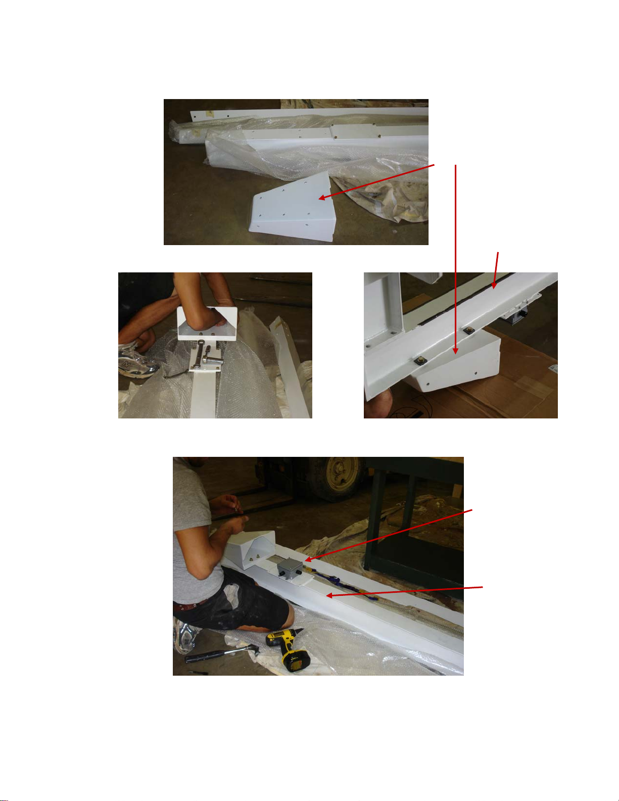
Description of FHTF: The FHTF consists of an upright structure, including an upper
weldment assembly, a hanging hoist mount, a chain hoist for raising and lowering the
unit under test (UUT), a load weigh system, a set of interconnecting cables, a
receptacle for three phase 400 hz power and a 28 volt power supply. The UUT control
signals are provided by a customer supplied set of controllers and pendant.
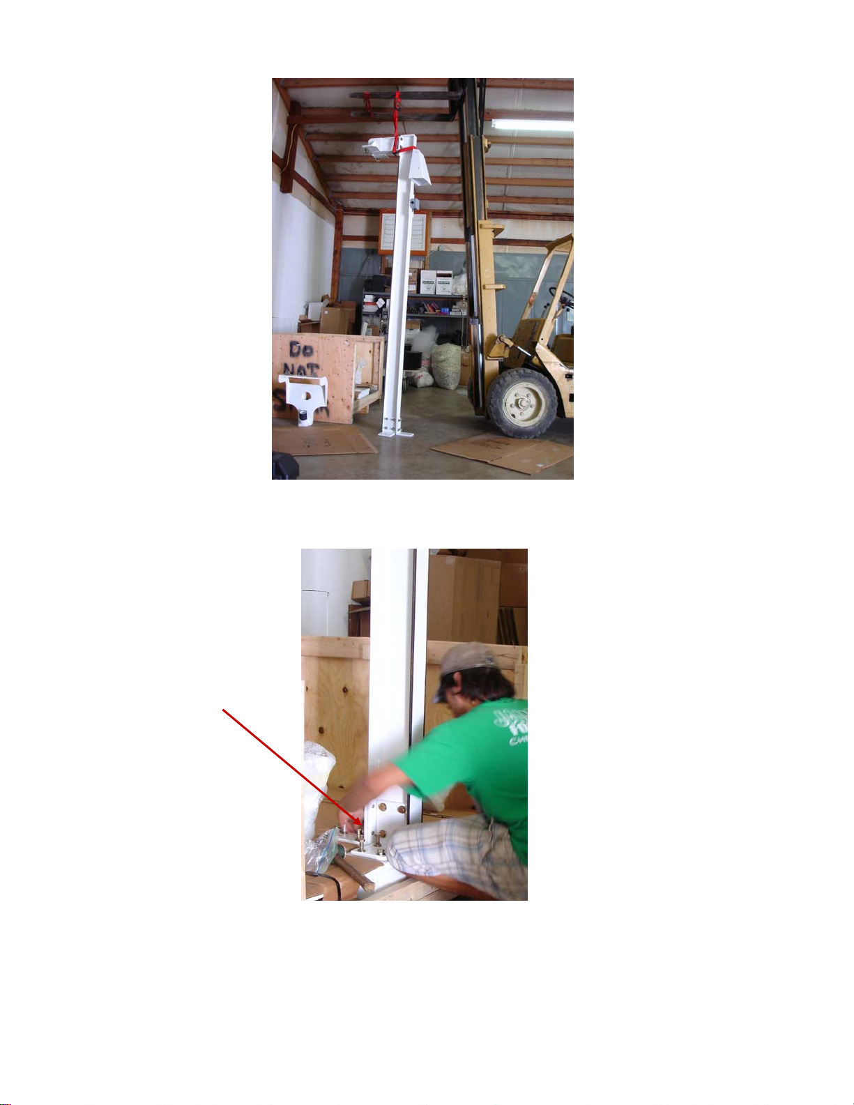
Theory of Operation: The upright structure is equipped with a chain hoist to raise
the UUT up to the top of the structure where it is attached to two load cells. The two
load cells provide signals to a load cell summing box where the signals are summed
and sent to a display. The load readout can be set to zero to tare the readout with no
load applied to the rescue hoist hook.
The wire rope tensile load is provided by the RHGSE. The RHGSE provides the
capability to extend the wire rope under approximately 300 lbs. maximum load, and
provides the capability to retract the wire rope under approximately 600 lbs. maximum
load.
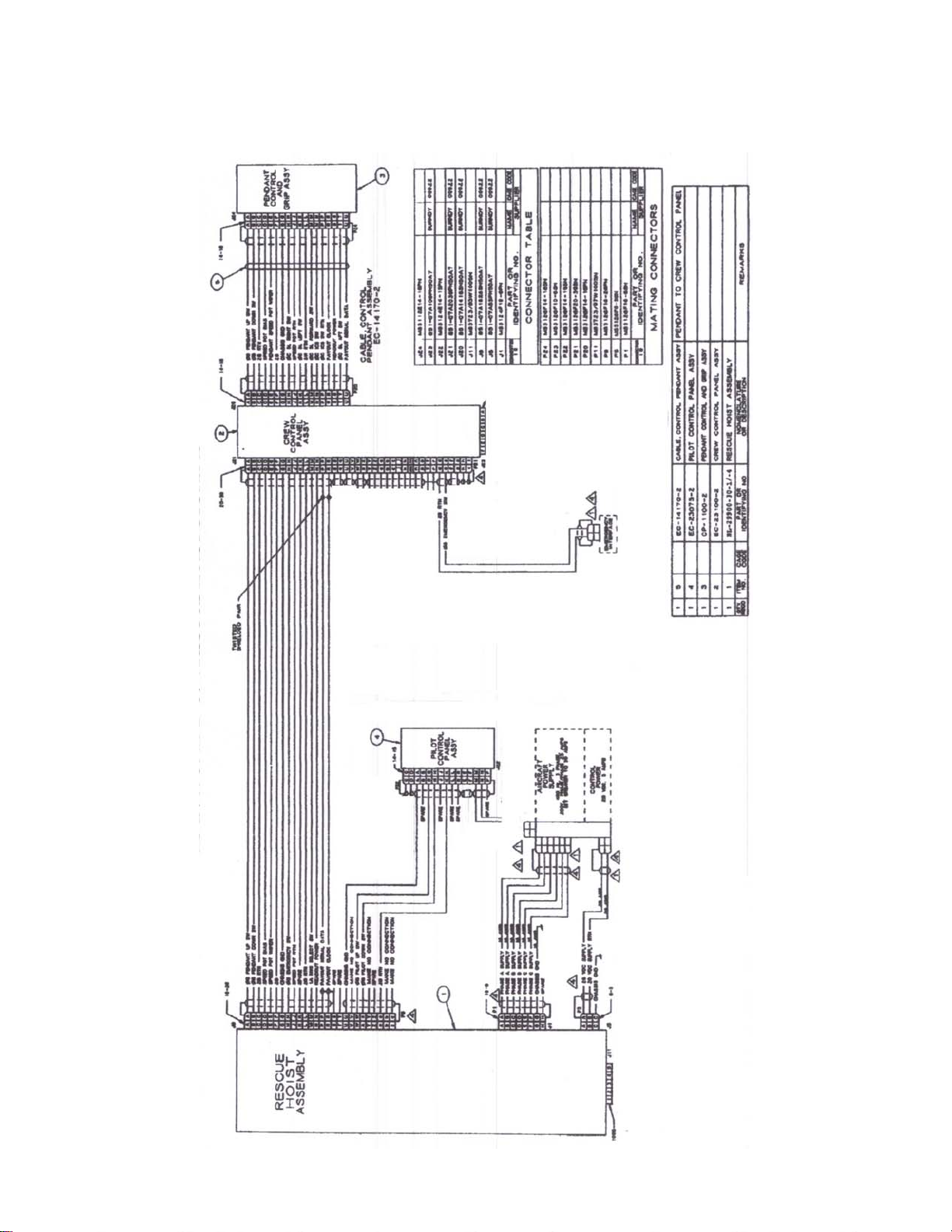
The 28 volts required to control the UUT control system is provided by a power supply
mounted in the junction box. The control pendant is mounted via its connector directly
to the front of the crew control panel, and the connectors are attached according to
figure 4.
A receptacle is provided to attach the connector from the 400 Hz power cart, and a
circuit breaker is provided to switch the three phase 400 Hz power.
Electrical loads:
200 volts 3 phase 400 Hz, approximately 8 KVA protected by a 30 Amp breaker
220 volts single phase approximately 5 amps
UUT operating criteria: The UUT is rated for 600 lbs and 350 feet per minute.

Fixed Hoist Test Facility Operation and Maintenance Manual ZOM-12000-7 rev 0
Page 4 of 24
This manual contains proprietary information and is not to be copied or disclosed without written
permission from Zephyr International LLC. Copyright 2006-2008
FHTF Limitations:
The FHTF is not intended to provide the capability to perform a complete acceptance
test as per the OEMs requirements but to allow the maintenance personnel to perform
checks of the system performance, set the hoist’s limit switches, adjust the levelwind,
and replace and condition the wire rope before the UUT is mounted onto the aircraft;
thus minimizing aircraft down time and flight time required if those procedures were
carried out on the aircraft.
System Pictures:
The Location Installation Requirements:
oShould be far from aircraft or equipment movement.
oShould be as close as possible to the AC power plug.
oWhen the system is being used it should be located away from any other
activities in the hanger, in order to prevent any injuries which might occur to the
personnel while they are focusing on the UUT and RHGSE.

Fixed Hoist Test Facility Operation and Maintenance Manual ZOM-12000-7 rev 0
Page 5 of 24
This manual contains proprietary information and is not to be copied or disclosed without written
permission from Zephyr International LLC. Copyright 2006-2008
System Floor Plan:
Top View
Dimensions in inches
Elevation View

Fixed Hoist Test Facility Operation and Maintenance Manual ZOM-12000-7 rev 0
Page 6 of 24
This manual contains proprietary information and is not to be copied or disclosed without written
permission from Zephyr International LLC. Copyright 2006-2008
System Interconnect Diagram

Fixed Hoist Test Facility Operation and Maintenance Manual ZOM-12000-7 rev 0
Page 7 of 24
This manual contains proprietary information and is not to be copied or disclosed without written
permission from Zephyr International LLC. Copyright 2006-2008
Assembly of FHTF:
oUnpack the crates and verify all the parts arrived in good condition.
oUse a forklift and lift the base weldment off the pallet and place it close to its
final position.
oAttach the base attachment angles to the I Beam using the labels to align each
bracket properly
Base Attachment Angles
I Beam

Fixed Hoist Test Facility Operation and Maintenance Manual ZOM-12000-7 rev 0
Page 8 of 24
This manual contains proprietary information and is not to be copied or disclosed without written
permission from Zephyr International LLC. Copyright 2006-2008
oLocate the upper brace mount and attach it to the I beam with its fasteners
oAttach the load cell summing box to the I beam.
Load Cell
Summing Box
Upper Brace Mount
I Beam
I Beam

Fixed Hoist Test Facility Operation and Maintenance Manual ZOM-12000-7 rev 0
Page 9 of 24
This manual contains proprietary information and is not to be copied or disclosed without written
permission from Zephyr International LLC. Copyright 2006-2008
oFlip the I beam over and attach the Hoist Hanging Weldment to it
oUse the beveled washers on the back surface of the beam flange as shown.
Hoist Hanging
Weldment
Beveled Washers

Fixed Hoist Test Facility Operation and Maintenance Manual ZOM-12000-7 rev 0
Page 10 of 24
This manual contains proprietary information and is not to be copied or disclosed without written
permission from Zephyr International LLC. Copyright 2006-2008
oWith two people or a crane stand up the I beam upright
oPlace the attaching brackets into position and attach all the screws.
Attaching brackets

Fixed Hoist Test Facility Operation and Maintenance Manual ZOM-12000-7 rev 0
Page 11 of 24
This manual contains proprietary information and is not to be copied or disclosed without written
permission from Zephyr International LLC. Copyright 2006-2008
oPlace the lower brace corner mount into position and loosely attach the
brackets with one bolt in each corner.
Identify the left and right diagonal braces and mount them between the lower and the
upper braces loosely.
Once all the holes have been lined up and the bolts inserted then tighten all the bolts
securely.
Left & Right
Diagonal Braces
Upper Brace Mount
Lower Brace Corner Mounts

Fixed Hoist Test Facility Operation and Maintenance Manual ZOM-12000-7 rev 0
Page 12 of 24
This manual contains proprietary information and is not to be copied or disclosed without written
permission from Zephyr International LLC. Copyright 2006-2008
oAttach the chain hoist support to the top of the hoist hanging weldment.
oThen attach the chain hoist with the chain cover facing outwards.
oTighten the nuts on the u-bolts securely to prevent the chain hoist from
escaping the u-bolt.
oInstall the S shaped load cells to the upper clevis mounts.
oAttach the hitch pins to prevent the clevis pins from escaping the clevis mounts.
Chain Hoist
Chain Hoist Support
Hoist Hanging Weldment
Upper Clevis Mounts
Load Cells
Hitch Pins

Fixed Hoist Test Facility Operation and Maintenance Manual ZOM-12000-7 rev 0
Page 13 of 24
This manual contains proprietary information and is not to be copied or disclosed without written
permission from Zephyr International LLC. Copyright 2006-2008
Slider Assembly,
Pins and hitch pins
oAttach an extension cord to the chain hoist and lower the hook to allow the
hanging hoist mount to be attached.
oUsing the chain hoist control, lift the hanging hoist mount up so it can be
attached to the slider assembly with its two pins.
oInsert the hitch pin retainer pins into the slider assembly pins.
oUsing the chain hoist raise the hanging hoist mount and slider upwards.
oEngage the lower tie rod ends of the load cell assemblies to the lower clevis
mounts of the hanging hoist mount with two clevis pins and hitch pins.
Hanging Hoist Mount
Post Mount

Fixed Hoist Test Facility Operation and Maintenance Manual ZOM-12000-7 rev 0
Page 14 of 24
This manual contains proprietary information and is not to be copied or disclosed without written
permission from Zephyr International LLC. Copyright 2006-2008
Controls Frame
3 Phase input power receptacle
Load Cell Readout and 28
VDC power Box
oMount the controls frame and the 3 phase input power receptacle as shown.
oMount the Load Cell Readout and 28 VDC power supply box as shown.
oOpen up the summing box and attach the load cells and the summing box
output to the load meter readout as per ZGS-12216-2.

Fixed Hoist Test Facility Operation and Maintenance Manual ZOM-12000-7 rev 0
Page 15 of 24
This manual contains proprietary information and is not to be copied or disclosed without written
permission from Zephyr International LLC. Copyright 2006-2008
Locate the FHTF in its final position and bolt the base to the floor if desired with the
floor attachment angles provided.

Fixed Hoist Test Facility Operation and Maintenance Manual ZOM-12000-7 rev 0
Page 16 of 24
This manual contains proprietary information and is not to be copied or disclosed without written
permission from Zephyr International LLC. Copyright 2006-2008
ZGS-12216-1
Load Cell Calibration
Install a hoist and make all electrical and mechanical attachments.
Configure the load cell readout according to section 4 of the DP25B-S User manual.
Input type is 100 mV
Set the decimal point to the default 0000
Dip switch setting is
12345678
COCOOCOO
Set Rd.CF R.2=1
If a 600 lbs load is available Scale the meter according to section 4.3.1.
With the UUT mounted on the hanging hoist mount with no load on it and with the
mount attached to the load cells, store the IN 1 value as the unscaled display reading
shown and set the RD 1 value to zero.
Then lower the UUT hook and attach the load and raise the 600 lbs weight until the
weight is off the ground.
Store the IN 2 reading and input the Rd 2 value as 600 lbs.
Note: This procedure can be performed with a lower or a higher load, and the Rd 2
value is then adjusted to the exact weight used. Using a value of 600 lbs insures
maximum accuracy, but is not essential.

Fixed Hoist Test Facility Operation and Maintenance Manual ZOM-12000-7 rev 0
Page 17 of 24
This manual contains proprietary information and is not to be copied or disclosed without written
permission from Zephyr International LLC. Copyright 2006-2008
Installing the UUT
oTo install the UUT the hanging hoist mount is lowered by raising the
hoist mount with the chain hoist hand control just enough to allow
removing the pins from the lower load cell clevis.
oRemove the pins and then lower the hanging mount to the lower
position as shown.
oInstall the UUT onto the post mount and install two ¼ inch pins.
oUsing the hand control raise the hanging hoist mount up to reattach
the two clevis pins, then lower the chain hoist to apply all the weight to the load
cells.
oMount the electrical control boxes in the opening on the frame as shown.
Pilot Control Panel
Crew Control Panel
3 Phase Power Receptacle
Load Cell Readout
28 VDC power on switch
Post Mount
Hanging Hoist Mount

Fixed Hoist Test Facility Operation and Maintenance Manual ZOM-12000-7 rev 0
Page 18 of 24
This manual contains proprietary information and is not to be copied or disclosed without written
permission from Zephyr International LLC. Copyright 2006-2008
Attach the plug from the Ground Power Cart to the receptacle provided.
oAttach the 220 V AC power
oAttach the ZGS-12201-1, ZGS-12202-1 and the ZGS-12203-1 cable
assemblies,
ZGS-12201-1 High Speed Hoist Test Stand Main Cable
3 phase breaker switch
220 VAC 50 Hz input power

Fixed Hoist Test Facility Operation and Maintenance Manual ZOM-12000-7 rev 0
Page 19 of 24
This manual contains proprietary information and is not to be copied or disclosed without written
permission from Zephyr International LLC. Copyright 2006-2008
ZGS-12203-1 28 VDC Input Power Cable
ZGS-12202-1 3 Phase Power Input Cable

Fixed Hoist Test Facility Operation and Maintenance Manual ZOM-12000-7 rev 0
Page 20 of 24
This manual contains proprietary information and is not to be copied or disclosed without written
permission from Zephyr International LLC. Copyright 2006-2008
System Procedures:
System Startup Procedure
Turn on the load indicator switch and allow the indicator to start up. Depending on the
calibration method used the load indicated is either zero or is the combined weight of
the UUT and the hanging hoist mount. To zero the reading press the Tare button on
the load indicator panel and the load indicated should go to zero.
System Operating Procedure
The system is design to be operated in conjunction with the Mobile RHGSE as shown
on the cover of the manual. ZOM-10000-5 describes the operation and maintenance
of the Mobile RHGSE in detail.
A checklist is provided to facilitate system operation, see page 21 and 22.
Test Procedures:
Test procedures are as described in the OEM’s operation and maintenance manual.
Detailed test procedures are not included herein as they are out of the scope of this
instruction manual.
System Maintenance
The connections to the UUT should be capped and stored in such a position that dirt is
not entrained into the system.
Attachments:
oElectrical Schematic ZGS-12216-2
oComponent Manuals
oLoad Cell Final Calibration Sheets
oStrain Gage Panel Meter User’s Guide
This manual suits for next models
1
Table of contents
Other Zephyr Industrial Equipment manuals
Popular Industrial Equipment manuals by other brands

MyBinding
MyBinding Formax FD 4040 instruction manual

Siemens
Siemens S7-1200 PROFIBUS operating instructions

Baileigh Industrial
Baileigh Industrial DDTM-4840-HD Operator's manual

Balluff
Balluff BTL5-H1 M Series Condensed guide

Siemens
Siemens 8MF1000-2HA operating instructions

DNS
DNS AS-410 Operation manual