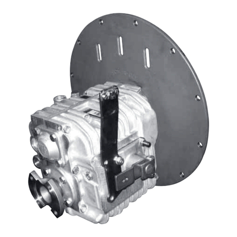
ZF ZF 45 IV User manual

OPERATING INSTRUCTIONS
ZF 45 IV
MARINE PROPULSION SYSTEMS


3
EN 3201.758.001a 2016-02
Copyright
Copyright © 2014 ZF Padova S.r.L.
All Rights Reserved
No part of this publication may be copied or reproduced in any form, including an electronic retrieval system or be
made available on the Internet, a public network, by satellite, or otherwise without the prior written permission of ZF
Padova S.r.L.
Legal Information
The information in this manual is believed to be accurate at the time of publication, but no responsibility, direct or con-
sequential, can be accepted for damage resulting from the use of this information. ZF Padova S.r.L., reserves the right
to make changes to any of its products without notice.
ZF Padova S.r.L.
Via Penghe, 48
I - 35030 Caselle di Selvazzano (PD)
ITALY
Phone +39 049 8299 311
Fax +39 049 8299 550
e-mail: info.zfpadova@zf.com
www.zf.com

4EN 3201.758.001a 2016-02

INDEX
5
EN 3201.758.001a 2016-02
INDEX
1. INTRODUCTION ...............................................................................................................7
1.1. INTRODUCTION ....................................................................................................................................7
1.2. CONVENTIONS FOR SAFETY INFORMATION IN TEXT ...........................................................................8
1.3. GENERAL INFORMATION ......................................................................................................................9
2. INSTALLATION AND OPTIONS .........................................................................................13
2.1. STANDARD INSTALLATION AND ASSEMBLY ........................................................................................13
2.2. PROPELLER SHAFT CONNECTION ........................................................................................................13
2.3. CONTROL VALVE SHIFT CONTROL LINKAGE .........................................................................................14
2.4. TOWING ................................................................................................................................................15
2.5. GEARBOX FASTENING ..........................................................................................................................16
3. TECHNICAL DATA ............................................................................................................17
3.1. TECHNICAL DATA .................................................................................................................................17
3.2. OIL TYPE ...............................................................................................................................................17
4. MAINTENANCE ................................................................................................................18
4.1. MAINTENANCE SCHEDULE ..................................................................................................................18
4.2. OIL LEVEL CHECK ..................................................................................................................................19
4.3. ADJUSTING SHIFT CONTROL LINKAGE .................................................................................................21
4.4. CHECKING FLEXIBLE COUPLINGS .........................................................................................................21
5. WARRANTY ......................................................................................................................22
6. TROUBLESHOOTING ........................................................................................................23

INDEX
6EN 3201.758.001a 2016-02

INTRODUCTION
7
EN 3201.758.001a 2016-02
1INTRODUCTION
1.1 INTRODUCTION
Notes to application support work of ZF
Propulsion System Competence Centre.
This document is to be intended only as a support material for the design and analysis of the Vessel Designer and Shi-
pyard in their role of unique Responsible of the final performance analysis, design, selection and decisions.
ZF Marine Propulsion System accept no liability for lack of performance for any expressed or unexpressed result..
In no way, this document is to be intended as a performance and/or commercial promise.
ZF Marine Propulsion System keeps the right to modify procedures, shapes, equipment, optionals, material, etc. men-
tioned or shown in the attached figures.
Also, some mentioned equipment might be optional.
The actual scope of supply will be limited to that mentioned in the offers issued by ZF Sales Dept
1.1.1 NOTICE
Read this handbook before proceeding with the installation.
The following symbols are used to highlight important information on technical reliability and safety:
NOTE:
When this symbol is displayed, the text alongside contains important information.
This symbol denotes a procedure that could damage the gearbox or associated equipment if not followed cor-
rectly.
This symbol denotes a procedure that could result in physical injury to the operator or to other persons in the
vicinity if not followed correctly.
CAUTION
DANGER

INTRODUCTION
8EN 3201.758.001a 2016-02
1.1.2 CONVERSION TABLE
1.2 CONVENTIONS FOR SAFETY INFORMATION IN TEXT
The following conventions apply for the safety information in these Operating Instructions:
• Ensure you read and understand all warnings prior to commissioning or repairing the product!
• Pass on all safety information to personnel involved in operating, maintenance, repair and transport!
S.I. INTERNATIONAL SYSTEM OTHERS
1 [mm] = 0.03937 [in]
10 [mm] = 0.3937 [in]
25.4 [mm] = 1 [in]
6.4516 [cm2]= 1 [sq.in]
1[m
2] = 1550 [sq. in]
16.387 [cm3]= 1 [cu.in]
0.473 [dm3]= 1 [U.S.pint]
1 [l] = 61.02 [cu. in]
1 [l] = 0.2642 [U.S. gal]
1.772 [g] = 1 [oz]
0.4536 [kg] = 1 [lb]
0.00070308 [kg/mm2]= 1 [lb/sq.in]
1 [bar] = 14.51 [psi]
1 [kg·m] = 7.246 [lb·ft]
30.48 [cm] = 1 [feet]
Describes a dangerous situation that can lead to serious injuries or death when not avoided.
Describes a dangerous situation that can lead to minor o moderate injuries when not avoided.
Describe a situation which can lead material damage when not avoided.
NOTE:
Serves to draw attention to special procedures, methods, information, use of aids and tools, etc. This document specially
highlights safety information according to US standard ANSI Z535 by marking the text with the above signal words according
to the degree of danger.
DANGER
WARNING
CAUTION
NOTICE

INTRODUCTION
9
EN 3201.758.001a 2016-02
1.3 GENERAL INFORMATION
1.3.1 MANUFACTURER'S ADRESS AND CONTACT
All gearboxes supplied by ZF Padova S.r.l.. are accompanied by the relative operating manual.
Further copies of this manual or of other technical documentation can be obtained from:
ZF Padova S.r.l.
Via Penghe 48,
35010 Caselle di Selvazzano PD
Tel. +39 - 049 8299485
Fax +39 - 049 8299560
1.3.2 GEARBOX DATA
IDENTIFICATION PLATE
The data of the gearbox will be found on the identification data plate:
the plate is located on top of the casing as shown.
This type of gearbox have been designed for high speed crafts such as example leisure boats and sport boats
It must be stored in a dry and temperate environment with its packs.
If the packing is removed, it's must be provided to the painting with anti-rust (if not present) of all outer surfaces gear-
box.
The gearbox is delivered without oil.

INTRODUCTION
10 EN 3201.758.001a 2016-02
1.3.3 TYPE GEARBOX IDENTIFICATION
The ZF 40 IV is different from ZF 41 IV for the unit "V drive":
In version 41 ZF V the propeller shaft passes through output flange.
The Main Unit is the same in both versions and in it there is the group clutches and the control unit
E.R.
• Rotation same as direction of rotation of engine
C.E.R.
• Rotation opposite to direction of rotation of engine
THE GEARBOX IS DESIGNED TO FUNCTION NORMALLY AND PRINCIPALLY IN E.R.
The gearbox should operate normally and principally in the E.R. and occasionally in C.E.R. (in reverse) .
The reverse function is performed through a planetary gear
The E.R. clutch is applied by the level of selector valve when it is placed in the [1] position (see fig. below). The engaged
clutch connects the input shaft to the output shaft that turn in C.E.R.
The output shaft rotation is transmitted in C.E.R. at 1.462:1 speed reduction ratio. The reverse clutch is applied by the
selector valve when it is placed in the reverse position.
The engaged clutch locks the planefary gear carrier. The input shaft rotation is transmitted to the output shaft through
ring gear and the three planetary pinions.
The Output shaft rotation is less than input shaft rotation at a 2.203:1 speed reduction ratio
Main Unit 40Vdrive Unit
Main Unit 41Vdrive Unit

INTRODUCTION
11
EN 3201.758.001a 2016-02
• Pos. 1: Output shaft rotation opposite to engine rotation
• Pos. N: Neutral
• Pos. 2: Output shaft rotation same as engine rotation
1.3.4 ELECTRIC CONTROL VALVE
The solenoid that corresponds to Pos. 1 of the control lever of the mechanical control valve, is the solenoid "A": the
energization of said solenoid rotates the output shaft in C.E.R. (Rotation opposite to direction of rotation of engine)
The transmission ratio, for both the engine and counterengine rotation modes, is stated on the identification plate. The
three types of operation are controlled by the control valve (mechanical or electrical).
The casing of the Main Unit also acts as a sump separated from the "V drive Unit" A magnet, placed under the sepa-
ration plate, removes steel particles from the oil, preventing damage to the hydraulic circuits.
Oil through the pump suction go to the control unit valve, where there is pressure regulation valve that reduces the
delivery pressure of the pump to the necessary clutch operating pressure.
MAIN UNIT OIL SUMP MUST BE COOLED BY THE COOLING SYSTEM OF THE BOAT USING THE HOLES 3/8 "(INLET
AND OUTLET) PROVIDED ON THE HOUSING.
In Unit V drive Unit there is an integrated heat exchanger for cooling oil inside casing V drive unit
THE HEAT EXCHANGER MUST ALWAYS BE CONNECTED TO THE COOLING WATER WITH THE PUMP RUNNING
BEFORE ENGAGE THE CLUTCH.
Before operating the gearbox, check oil leves (both Main Unit and V-drive Unit)
See Technical data (p. 17).
CAUTION

INTRODUCTION
12 EN 3201.758.001a 2016-02
1. Breather Main Unit
2. From external cooler to control unit in Main Unit
3. 9/16 UNF control valve sensor connector
4. Valve control lever
5. From oil pump outlet to external cooler
6. Spline SAE Input Shaft
7. 1/8 - 27 NPT pressure connector C.E.R
8. Identification plate
9. 1/8 - 27 NPT pressure connector E.R
10.Oil dipstick for Main Unit (filling)
11.Output shaft
12.Oil dipstick for V drive Unit (filling)
13.V-drive integrated cooler
14.Anodes
15.Breather V drive Unit
16.V drive Unit
17.Main Unit
1 2 3 4 9 8 10 11 12 13
6 5 7
13 12 15 11 16 17
14

INSTALLATION AND OPTIONS
13
EN 3201.758.001a 2016-02
2 INSTALLATION AND OPTIONS
The gearbox must be filled with oil and the oil level checked before use. (see Maintenance (p. 18))
Using the gearbox with insufficient oil could damage the gears. Too much oil could cause leakages through the gaskets
and breather and considerably increase the running temperature.
An oil leak can also be a symptom of a possible failure.
Checks should always be made during the repair of any part of the gearbox to prevent even complaints.
Check if the gearbox is correctly attached to the engine flywheel: loose hub or hub not correctly center.
LOOSE HUB OR HUB NOT CORRECTLY CENTERED, CAN CAUSE WEAR OF THE GEAR PUMP
Under normal conditions, the drive should be reversed when the engine is idling. In emergencies, the drive can be
reversed with the engine running at maximum speed. Repeatedly inverting with reversing a maximum engine speed,
the life of group friction is significantly shortened.
MAKE SURE THE ENGINE AND PROPELLER ARE AT A STANDSTILL BEFORE CARRYING OUT ANY KIND OF OPE-
RATION ON THE GEARBOX.
2.1 STANDARD INSTALLATION AND ASSEMBLY
A flexible coupling fitted to the engine must be provided for absorb the vibrations.
If necessary, in addition to the normal flexible coupling fitted to the engine, fit an extra damper
Check the flywheel if is correctly centered using a dial indicator on the flywheel face.
Rotate the engine by hand while watching the dial, if the total indicated runout of the flywheel face is off more than
0.1 mm (0.005") it must be replaced.
Check the flywheel housing bore: mount a dial indicator on the flywheel face with the tip on the bore of the flywheel
housing. Rotate the engine by hand while watching the dial. If the total indicated runout of the flywheel housing bore
is off more than 0.2 mm (0.008") the flywheel housing must be replaced
If this does not occur, means that the faces of the coupling exceeds the maximum permissible eccentricity.
2.2 PROPELLER SHAFT CONNECTION
You are advised to use a thrust bearing to reduce the inevitable axial strain on the gearbox.
Performance data for the propeller shaft bearing will depend on the loads applied during operation, and must be spe-
cified by the designer and builder of the boat.
The alignment must be checked with the boat in the water, as the deformation of the hull in the water is enough to
alter an alignment done on stands.
You must match the coupling and shaft so that it is a concentricity within 0.02 mm (0.001 ")
CAUTION

INSTALLATION AND OPTIONS
14 EN 3201.758.001a 2016-02
Check the condition of the oil coolers.
Flush the oil circuit of the coolers and test the cooler for leaks, both in the oil and water chambers.
Prior to removal of the gearbox from the boat the alignment of the engine to the shaft should be checked and noted.
A shaft that is out of alignment can cause numerous problems inside the engine to the shaft should be checked and
noted.
A shaft that is out of alignment can cause numerous problem inside the gearbox.
If the gearbox is removed there is nothing to guarantee that the engine will return to the original location.
Control of his alignment condition before removal and take note.
Check the available correct oil pressure in neutraI, forward and reverse
This may not be possible without disconnecting the propeller shaft from the transmission if the transmission is locked
into gear.
2.3 CONTROL VALVE SHIFT CONTROL LINKAGE
When installing the shift control linkage, make sure the travel on the lever takes it right to the travel limit, when ope-
rated from the bridge console.
If it doesn't, this could result in the burning of the clutches because the oil flow rate will be too low.

INSTALLATION AND OPTIONS
15
EN 3201.758.001a 2016-02
2.4 TOWING
Towing can be done continuously for 8 hours.
Check that the oil temperature does not go over 80°C.
The position of the control lever is of no importance when the engine is off.
DO NOT PERFORM ANY OPERATIONS ON THE TRANSMISSION DURING TOWING, AS THE PROPELLER MAY
START TURNING.
ELECTRICAL SYSTEM BREAKDOWN.
EMERGENCY SYSTEM WITH ELECTRICAL CONTROL VALVE
If a breakdown occurs in the electrical system or the solenoids of electric valve, the clutches can be engaged manually
with the mechanical system "Came home".
You need to remove cover [1], to operate this system
Find the solenoid corresponding to engage the clutch:
• solenoid A
– rotation propeller shaft opposite to engine rotation
– With the engine at minimum speed, push and screw the pin [2] until it stops.
• solenoid B
– rotation propeller shaft same to engine rotation
– With the engine at minimum speed, pull and unscrew the bolt [2] until it stops.
To return in neutral with the engine idling, screw or unscrew the pin [2] to return it to its original position
1
2

INSTALLATION AND OPTIONS
16 EN 3201.758.001a 2016-02
2.5 GEARBOX FASTENING
a. Gearbox fastening holes
A

TECHNICAL DATA
17
EN 3201.758.001a 2016-02
3TECHNICALDATA
3.1 TECHNICAL DATA
OIL PUMP FLOW RATE:
19 litres at 4500 rpm
OPERATING PRESSURE AT 4500 RPM:
14 - 16 bar
OPERATING PRESSURE AT 1500 RPM:
12 - 15 bar
OPERATING PRESSURE AT 700 RPM:
8 - 12 bar
LUBRICATION PRESSURE AT 1500 RPM:
> 0.5 bar
MAX. TRANSVERSE INCLINATION DURING OPERATION:
+/- 15 deg
MAX. LONGITUDINAL INCLINATION DURING OPERATION:
+/- 25 deg
3.2 OIL TYPE
OIL RECOMMENDED IS SAE 30
TYPE MASS (WITHOUT OIL) OIL TEMPERATURE [°C] OIL CAPACITY [DM3]
Main Unit 21 40 to 80 1.1 to 1.3
40 V Drive / 41 V Drive 16 40 to 80 0.9 to 1.0
TYPE SPECIFICATION VISCOSITY
SAE 30 SAE 30 102 cst (40°C) - 11.6 cst (100°C)
Mobil ATF 200 ISO 46 45 cst (40°C) - 8 cst (100°C)
Mobil ATF 220 DEXRON II D ISO 32 35.2 cst (40°C) - 6.9 cst (100°C)

MAINTENANCE
18 EN 3201.758.001a 2016-02
4 MAINTENANCE
4.1 MAINTENANCE SCHEDULE
ANNUALLY /
500 HOURS
SIX MONTHS /
250 HOURS DAILY AFTER THE FIRST 50
HOURS OPERATION MAINTENANCE OPERATIONS
vvv Checkforoilleaks
v v v Check oil levels
v v v Check external threaded fasteners
v v v Check and adjust shift control linkage
v v Clean gearbox externally
v v Lubricate external moving parts
v v Oil Change
vInspect flexible coupling
vCheck resilient mounts
vZinc anodes replacement
vCleaning heat exchangers

MAINTENANCE
19
EN 3201.758.001a 2016-02
4.2 OIL LEVEL CHECK
1. Loosen fluid dipstick by turning the grip counterclockwise.
2. Wipe dipstick with a clean and dustfree cloth.
3. Check oil level:
– For Main Unit: completely screw the dipstick. Remove dipstick and check that fluid level is between minimum
and maximum marks.
Do not work on the transmission when being towed, or anchoring in a river because the propeller may rotate.
Transmission fluid level may be checked in cold or hot condition.
NOTE:
Always check fluid level before operating transmission.
CAUTION
MAX.
MIN.

MAINTENANCE
20 EN 3201.758.001a 2016-02
– For V Drive Unit: insert dipstick without screwing in. Remove dipstick and check that fluid level is between mi-
nimum and maximum marks.
4. Insert the dipstick and lock it by turning the grip clockwise.
5. Let engine run at idle speed with shifting lever in neutral position until fluid cooler and all pipelines are filled with
fluid.
6. Switch off engine and check fluid level within a short time. If necessary, top fluid level off to the dipstick mark. The
fluid level on the dipstick should be between the min. and max. marks. The fluid level must be checked again after
a short driving period.
According to the type and arrangement of the cooler and pipelines a certain amount of oil will collect after
stopping the engine and will flow back into the transmission after a longer rest period. This may cause the oil
level in the transmission to exceed the max. mark. Do not remove off the surplus oil but proceed according to
steps.
MAX.
MIN.
CAUTION
Table of contents
Other ZF Boating Equipment manuals
Popular Boating Equipment manuals by other brands

Batsystem
Batsystem PB1200BL Mounting instructions

Gumotex
Gumotex FRAMURA user guide

PERFECTPASS
PERFECTPASS DigitalPro 6.5NG manual

MINN KOTA
MINN KOTA RAPTOR owner's manual

Simpso-lawrence
Simpso-lawrence Horizon 600 Owners installation, operation & servicing manual

Vetus
Vetus BOW4512D Operation manual and installation instructions