ZIEHL UFR1001E User manual

ZIEHL industrie –elektronik GmbH + Co KG
Daimlerstr.13, 74523 Schwäbisch Hall, Germany
+ 49 791 504-0, [email protected]e, www.ziehl.de
Temperature Relays and MINIKA® Mains Monitoring Digital Panelmeters MINIPAN® Switching Relays and Controls Measuring Transducers Grid- and Plant Protection
Operating Manual UFR1001E
updated: 2018-11-22/Ba
from Firmware: 0-09
UFR1001E 12420-0701-14 Page
1
/ 34 www.ziehl.de
- NA-protection according to VDE-AR-N 4105:2011+2018-11, power generators at the low voltage grid,
TAR medium voltage VDE-AR-N 4110:2018-11
- for use in power generators at the medium voltage grid according to BDEW
- with selectable vector shift detection and Rate of Change of Frequency (ROCOF,df/dt)
New, Firmware 0-09:
program 2 for low voltage VDE-AR-N 4105:2018-11
4 new programs (11-14) for medium voltage according to 4110:2018-11
(Display of the firmware version: 8Info8→8fnr 8or press “Set” for >10s)
Certificates see:
https://www.ziehl.com/en/products/?view=detail&detail=54

UFR1001E 12420-0701-14 Page
2
/ 34 www.ziehl.de
Table of contents
1Display and controls .............................................................................................................................. 4
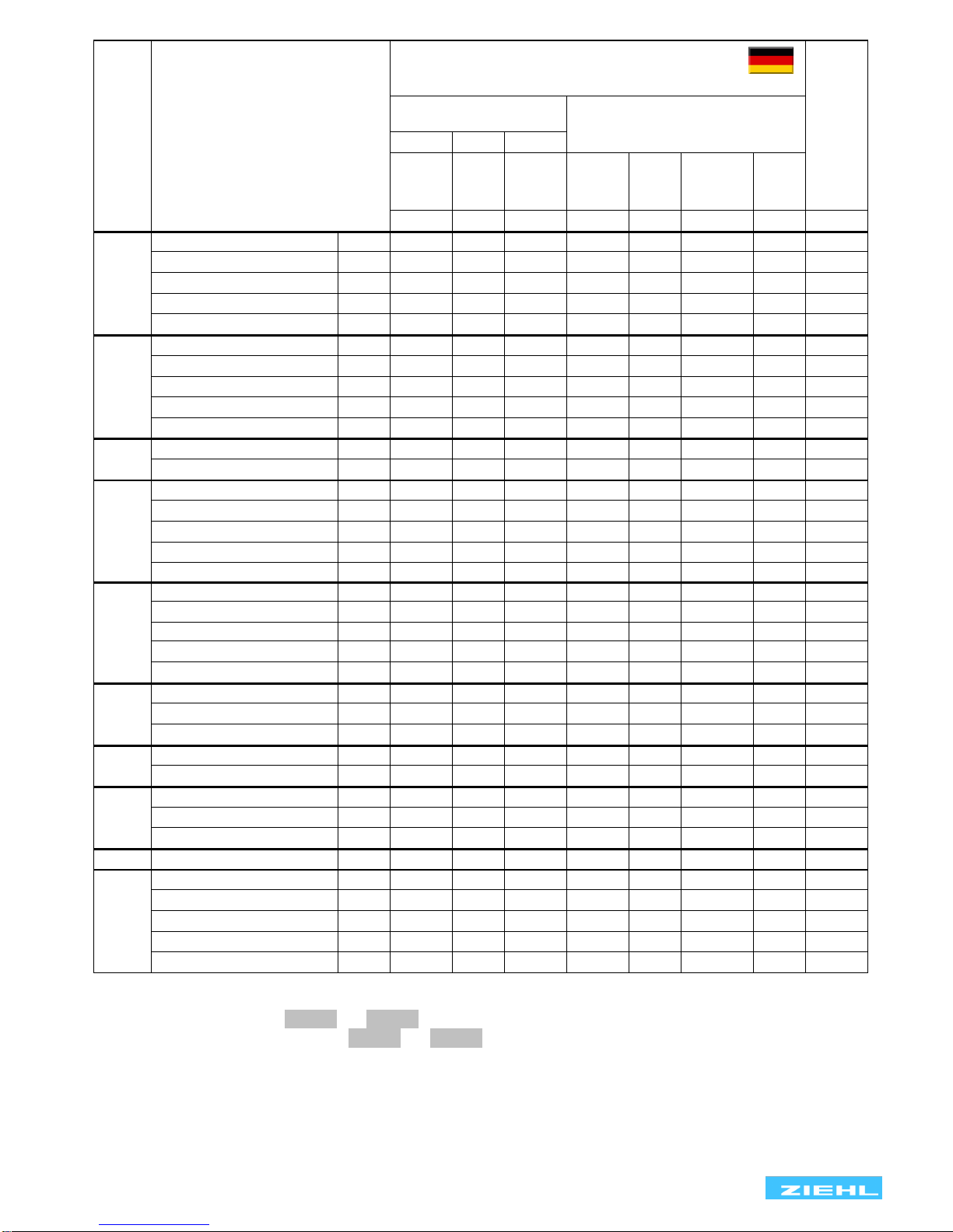
2Default settings and firmware version, VDE-AR-N 4105 + BDEW ....................................................... 5
3Default settings and firmware version, VDE-AR-N 4110:2018-11........................................................ 7
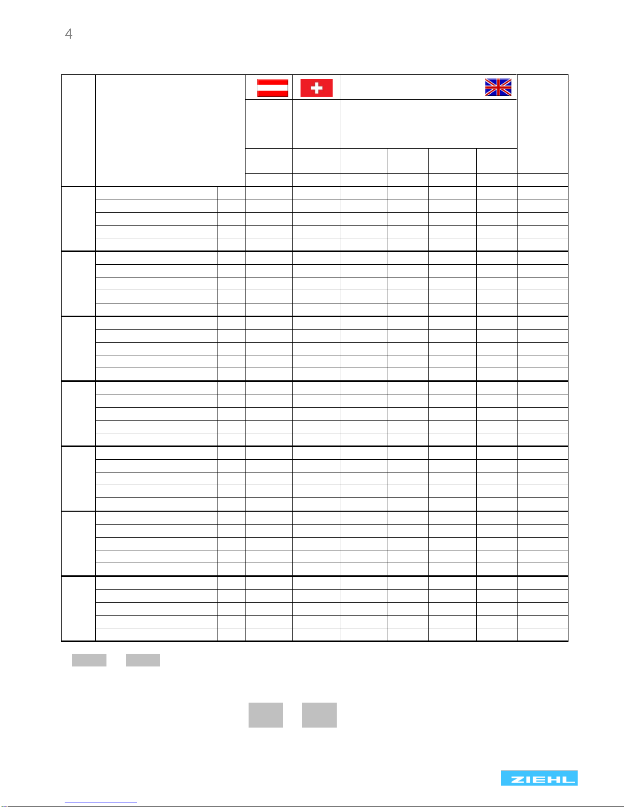
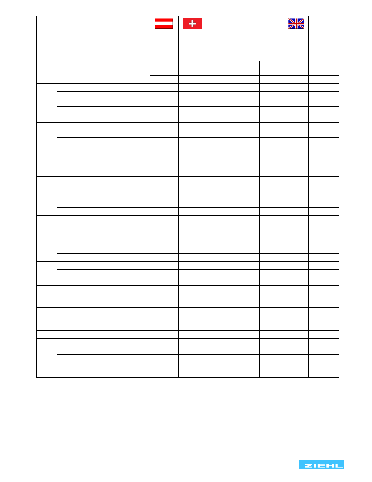
4Default settings and firmware version, ÖVE/ÖNORM E 8001-4-712, G83/2+G59/3............................. 9
5Application and brief description........................................................................................................ 11
6Summary of the functions ................................................................................................................... 11
7Connection diagrams........................................................................................................................... 12
7.1 1x PV, 1x section switch (VDE-AR-N 4105:2018-11)................................................................... 12
7.2 1x PV, 2x section switch (VDE-AR-N 4105:2011)........................................................................ 13
7.3 Multiple PV with section switch and with a series-switched NC's as feedback contacts............... 14
7.4 Multiple PV with section switch and with a parallel-switched closing contacts as feedback.......... 15
7.5 1x PV, 1x section switch with nc/normally closed contacts (VDE-AR-N 4110:2018-11)................ 16
8Important information .......................................................................................................................... 17
9Assembly .............................................................................................................................................. 17
10 Detailed description ............................................................................................................................. 18
10.1 Description of the connections..................................................................................................... 18
10.2 Functional characteristics ............................................................................................................ 19
11 Commissioning..................................................................................................................................... 20
11.1 Program setup............................................................................................................................. 20
11.2 Control chart Pr 2-6, 11-14, 20-23 ............................................................................................... 21
11.3 Control chart Pr 1, 7, 10, 15......................................................................................................... 22
11.4 Description of the parameters...................................................................................................... 23
11.5 Display mode (last decimal point off) ........................................................................................... 24
11.6 Menu mode (last decimal point on).............................................................................................. 24
11.7 Configuration mode (last decimal point flashes)........................................................................... 24
11.8 Test mode (timekeeping only activated and connected feedback contacts)................................. 24
11.9 Alarm counter.............................................................................................................................. 25
11.10 Cumulative alarm time (display in hours).................................................................................. 25
11.11 Alarm memory.......................................................................................................................... 25
11.12 Standby counter and standby time........................................................................................... 26
11.13 Code lock................................................................................................................................. 26
11.14 Sealing..................................................................................................................................... 27
11.15 Simulation................................................................................................................................ 27
11.16 Possible indications in display.................................................................................................. 28
12 Technical Data...................................................................................................................................... 29
13 Maintenance and repair........................................................................................................................ 30
14 Troubleshooting and measures .......................................................................................................... 31
15 Construction form V6........................................................................................................................... 32
16 Adjustment values table VDE-AR-N 4105:2011, Low Voltage Pr 1+7................................................ 33
17 Adjustment values table BDEW June 2008, acc 3.2.3.3-1, Medium Voltage Pr 3-6.......................... 33
18 Adjustment values table VDE-AR-N 4105:2018-11, 6. table 2, Pr 2.................................................... 33
19 Adjustment values VDE-AR-N 4110:2018-11, higher protection Pr11+12......................................... 34

UFR1001E 12420-0701-14 Page
3
/ 34 www.ziehl.de
20 Adjustment values VDE-AR-N 4110:2018-11, Unit Protection Pr13+14............................................. 34

UFR1001E 12420-0701-14 Page
4
/ 34 www.ziehl.de
Display and controls
1
Test button
Press
briefly
Output relays de-energize immediately. If Y1+Y2 are connected and the feedback signal is
activated, the tripping time is displayed until the next time a button is pressed / max 60s
2
LEDs frequency / voltage limit value undercut / exceeded (red)
On, 8AL 8or 8AL M8
Limit value undercut / exceeded
FLASHES, 8AL 8or 8AL M8
Reset delay 8dof 8counting down
3
LED vector surge (VSR, red)
ON, 8AL 8
Threshold value for vector shift exceeded
FLASHES, 8AL8
Reset delay 8dof 8counting down
4
LEDs relay status (yellow)
OFF
Relay is released
ON
Relay operating
5
Digital display 4-digits (red)
Depending on program, display of current voltage, frequency, vector shift, average value
Displays the alarm signals, e.g. 8AL 8, 8aL M8
Displays the errors with error code e.g. 8Err98
6
LED Time (yellow)
ON
A time is displayed
7
Last decimal point (red)
OFF
Display mode
Illuminated
Menu mode
Flashes
Configuration mode
8
Set/Reset key (in display mode, normal state)
Press briefly
Display of next measured value / alarm counter
Press for > 2 s
Reset, quit error messages
Press for > 4 s
Displays the program, e.g. 8Pr 18
Press for > 10 s
Displays the software version, e.g. 80-058
9
Up / Down key (in display mode, normal state)
Press briefly
Change to the menu mode, display of alarm memory (Down) / cumulative time
of alarms, standby counter, standby time (Up), pushing Set button for ≥ 2 s
resets the stored values
Press for > 2 s
Display of MAX (Up) / MIN (Down) - measured values, additional pushing of Set
button for ≥ 2 s deletes the stored values
10
LEDs measurement allocation (yellow)
LEDs
Measured value
Lx and N ON
Voltage value (L1 against N, L2 against N, L3 against N)
Lx and Ly ON
Voltage value (L1 against L2, L2 against L3, L1 against L3)
Lx FLASHING quickly
Vector surge (L1, L2, L3)
L1 FLASHING
Frequency
11
Sealable button + LED
Press for > 2 s
Lock / Unlock
LED red
Settings and simulation mode are locked,
While attempting to set, 8LOc 8is displayed for 3s
LED green
Setting and simulation enabled

UFR1001E 12420-0701-14 Page
5
/ 34 www.ziehl.de
Default settings and firmware version, VDE-AR-N 4105 + BDEW
When changing programs, all parameters are reset to the default settings.
Menu
Parameter / Unit
Default settings
Users
Data
Low voltage
VDE-AR-N 4105:
Medium voltage BDEW
2011
2018
2011
3 AC
+N
230V
3 AC
+N
230V
2/1 AC
+N
230V
3 AC
+N
57,7V
3 AC
100V
3/2/1AC
+N
230V
3 AC
400V
Pr1 *
Pr2
Pr7
Pr3
Pr4
Pr5
Pr6
U,,
59.S2
59>S2
u,, Alarm on/off
-
on
-
on
on
on
on
u,, Overvoltage
V
-
287
-
66.4
115
264
458
H,, Hysteresis
V
-
35.0
-
1.0
1.0
3.0
3.0
dal Response time
s
-
0.10
-
0.10
0.10
0.10
0.10
dof OFF-delay
s
-
60
-
60
60
60
60
U,
59.S1
59>S1
u, Alarm on/off
on
off
on
On
on
on
on
u, Overvoltage
V
264
264
264
62.3
108
249
430
H, Hysteresis
V
5.0
12.0
5.0
1.0
1.0
3.0
3.0
dal Response time
s
0.10
0.10
0.10
60.0
60.0
60.0
60.0
dof OFF-delay
s
60
60
60
60
60
60
60
UM:
59-Av
UM Alarm on/off
on
on
on
Off
Off
off
Off
UM Overvoltage
V
253
253 3
253
63.5
110
253
438
HM Hysteresis
V
3.0
5.0
3.0
1.0
1.0
3.0
3.0
dal Response time
s
0.10
0.10
0.10
0.10
0.10
0.10
0.10
dof OFF-delay
s
60
60
60
60
60
60
60
U_
27.S1
27<S1
u_ Alarm on/off
on
On
on
On
On
on
on
u_ Undervoltage
V
184
184
184
46.2
80.0
184
318
H_ Hysteresis
V
5.0
12.0
5.0
1.0
1.0
3.0
3.0
dal Response time
s
0.10
3.00 3
0.10
2.70
2.70
2.70
2.70
dof OFF-delay
s
60
60
60
60
60
60
60
U__
27.S2
27<S2
u__ Alarm on/off
-
On
-
Off
Off
off
Off
u__ Undervoltage
V
-
103
-
26.0
45.0
104
180
H__ Hysteresis
V
-
93.0
-
1.0
1.0
2.0
2.0
dal Response time
s
-
0.30 3
-
0.30
0.30
0.30
0.30
dof OFF-delay
s
-
60
-
60
60
60
60
F,,
81.S2
81>S2
F,, Alarm on/off
-
off
-
off
Off
off
Off
F,, Overfrequency
Hz
-
52.50
-
51.50
51.50
51.50
51.50
H,, Hysteresis
Hz
-
2.40 ²
-
1.45 1
1.45 1
1.45 1
1.45 1
dal Response time
s
-
0.10
-
0.10
0.10
0.10
0.10
dof OFF-delay
s
-
60
-
60
60
60
60
F,
81.S1
81>S1
F, Alarm on/off
On
On
on
on
on
on
On
F, Overfrequency
Hz
51.50
51.50
51.50
51.50
51.50
51.50
51.50
H, Hysteresis
Hz
1.45 1
1.40 ²
1.45 1
1.45 1
1.45 1
1.45 1
1.45 1
dal Response time
s
0.10
0.10
0.10
0.10
0.10
0.10
0.10
u,, Alarm on/off
s
60
60
60
60
60
60
60
* factory preset
1= Autohysteresis 50,05 Hz
² = Autohysteresis 50,10 Hz
3= Parameter can changed independently of the code lock (only in Pr2)
Display of the program: 8Info8→8Pr 8or when switching on
Display of the firmware version: 8Info8→8fnr 8

UFR1001E 12420-0701-14 Page
6
/ 34 www.ziehl.de
Menu
Parameter / Unit
Default settings
Users
Data
Low voltage
VDE-AR-N 4105:
Medium voltage
VDE-AR-N 4110:2018-11
2011
2018
2011
3 AC
+N
230V
3 AC
+N
230V
2/1 AC
+N
230V
3 AC
+N
57,7V
3 AC
100V
3/2/1AC
+N
230V
3 AC
400V
Pr1 *
Pr2
Pr7
Pr3
Pr4
Pr5
Pr6
F_
81.S1
81<S1
F_ Alarm on/off
on
On
on
on
on
on
on
F_ Underfrequency
Hz
47.50
47.50
47.50
47.50
47.50
47.50
47.50
H_ Hysteresis
Hz
1.00
0.10
1.00
1.00
1.00
1.00
1.00
dal Response time
s
0.10
0.10
0.10
0.10
0.10
0.10
0.10
dof OFF-delay
s
60
60
60
60
60
60
60
F__
81.S2
81<S2
F__ Alarm on/off
-
Off
-
off
off
off
off
F__ Underfrequency
Hz
-
47.00
-
47.50
47.50
47.50
47.50
H__ Hysteresis
Hz
-
0.60
-
1.00
1.00
1.00
1.00
dal Response time
s
-
0.10
-
0.10
0.10
0.10
0.10
dof OFF-delay
s
-
60
-
60
60
60
60
uonf
uonf on/off
off
Off
off
off
off
off
off
uonf voltage
V
46.0
46.0
46.0
20.0
20.0
46.0
46.0
Vsr
78
vsr Alarm on/off
stby
Stby
stby
stby
stby
stby
stby
vsr Vector shift
°
10.0
10.0
10.0
10.0
10.0
10.0
10.0
dof OFF-delay
s
3
3
3
3
3
3
3
dEon Suppression time
s
2
2
2
3
3
3
3
vsr Number of phases
3ph
3ph
3ph
3ph
3ph
3ph
3ph
Rocf
81r
rocf Alarm on/off
Off
Off
Off
Off
Off
Off
Off
dfdt delta f / delta t
Hz/s
0.800
2.000
0.800
0.800
0.800
0.800
0.800
Per periods
20
20
20
20
20
20
20
dal Response time
s
0.10
0.10
0.10
0.10
0.10
0.10
0.10
dof OFF-delay
s
60
60
60
60
60
60
60
rEL
trEL Response time Yx
s
5.0
5.0
5.0
off
off
off
off
dofa Mode
ind
Ind
ind
ind
ind
ind
ind
dofa Off-delay all
s
0
0
0
0
0
0
0
ddi
ddi Display delay
s
0.5
0.5
0.5
0.5
0.5
0.5
0.5
dit Display duration SCn
s
3.5
3.5
3.5
3.5
3.5
3.5
3.5
Si
U Voltage
V
230
230
230
57.7
100
230
400
F Frequency
Hz
50.00
50.00
50.00
50.00
50.00
50.00
50.00
vsr Vector shift
°
0.0
0.0
0.0
0.0
0.0
0.0
0.0
CodE
pin Pincode
504
504
504
504
504
504
504
Info
fnr Firmware version
0-09
0-09
0-09
0-09
0-09
0-09
0-09
snr Serial number
xxxx
xxxx
xxxx
xxxx
xxxx
xxxx
xxxx
h Operating hours
h
xxxx
xxxx
xxxx
xxxx
xxxx
xxxx
xxxx
err Error counter
xxx
xxx
xxx
xxx
xxx
xxx
xxx
Pr Program
1
2
7
3
4
5
6
* factory preset
Display of the program: 8Info8→8Pr 8or when switching on
Display of the firmware version: 8Info8→8fnr 8

UFR1001E 12420-0701-14 Page
7
/ 34 www.ziehl.de
Default settings and firmware version, VDE-AR-N 4110:2018-11
When changing programs, all parameters are reset to the default settings.
Menu
Parameter / Unit
Default settings
Medium voltage
VDE-AR-N 4110:2018-11
Users Data
3 AC
+N
57,7V
3 AC
100V
3/2/1AC
+N
230V
3 AC
400V
Pr11
Pr12
Pr13
Pr14
U,,
59.S2
59>S2
u,, Alarm on/off
on
on
on
on
u,, Overvoltage
V
69.2
120
287
498
H,, Hysteresis
V
1.0
1.0
3.0
3.0
dal Response time
s
0.30
0.30
0.10
0.10
dof OFF-delay
s
60
60
60
60
U,
59.S1
59>S1
u, Alarm on/off
On
on
off
off
u, Overvoltage
V
63.5
110
249
430
H, Hysteresis
V
1.0
1.0
3.0
3.0
dal Response time
s
180.0
180.0
60.0
60.0
dof OFF-delay
s
60
60
60
60
UM:
59-Av
UM Alarm on/off
Off
Off
off
Off
UM Overvoltage
V
63.5
110
253
438
HM Hysteresis
V
1.0
1.0
3.0
3.0
dal Response time
s
0.10
0.10
0.10
0.10
dof OFF-delay
s
60
60
60
60
U_
27.S1
27<S1
u_ Alarm on/off
On
On
on
on
u_ Undervoltage
V
46.2
80.0
184
318
H_ Hysteresis
V
1.0
1.0
35.0
35.0
dal Response time
s
2.70
2.70
1.00
1.00
dof OFF-delay
s
60
60
60
60
U__
27.S2
27<S2
u__ Alarm on/off
Off
Off
off
Off
u__ Undervoltage
V
26.0
45.0
111
180
H__ Hysteresis
V
1.0
1.0
108
108
dal Response time
s
0.30
0.30
0.30
0.30
dof OFF-delay
s
60
60
60
60
F,,
81.S2
81>S2
F,, Alarm on/off
off
Off
on
On
F,, Overfrequency
Hz
51.50
51.50
52.50
52.50
H,, Hysteresis
Hz
1.40 ²
1.40 ²
2.40 ²
2.40 ²
dal Response time
s
0.10
0.10
0.10
0.10
dof OFF-delay
s
60
60
60
60
F,
81.S1
81>S1
F, Alarm on/off
off
off
on
on
F, Overfrequency
Hz
51.50
51.50
51.50
51.50
H, Hysteresis
Hz
1.40 ²
1.40 ²
1.40 ²
1.40 ²
dal Response time
s
5.40
5.40
5.00
5.00
u,, Alarm on/off
s
60
60
60
60
² = Autohysteresis 50,10 Hz
Display of the program: 8Info8→8Pr 8or when switching on
Display of the firmware version: 8Info8→8fnr 8

UFR1001E 12420-0701-14 Page
8
/ 34 www.ziehl.de
Menu
Parameter / Unit
Default settings
Medium voltage
VDE-AR-N 4110:2018-11
Users Data
3 AC
+N
57,7V
3 AC
100V
3/2/1AC
+N
230V
3 AC
400V
Pr11
Pr12
Pr13
Pr14
F_
81.S1
81<S1
F_ Alarm on/off
off
off
on
on
F_ Underfrequency
Hz
47.50
47.50
47.50
47.50
H_ Hysteresis
Hz
2.40 4
2.40 4
2.40 4
2.40 4
dal Response time
s
0.40
0.40
0.10
0.10
dof OFF-delay
s
60
60
60
60
F__
81.S2
81<S2
F__ Alarm on/off
Off
Off
Off
Off
F__ Underfrequency
Hz
47.50
47.50
47.50
47.50
H__ Hysteresis
Hz
2.40 4
2.40 4
2.40 4
2.40 4
dal Response time
s
0.10
0.10
0.10
0.10
dof OFF-delay
s
60
60
60
60
uonf
uonf on/off
off
off
off
off
uonf voltage
V
20.0
20.0
46.0
46.0
Vsr
78
vsr Alarm on/off
stby
stby
stby
stby
vsr Vector shift
°
10.0
10.0
10.0
10.0
dof OFF-delay
s
3
3
3
3
dEon Suppression time
s
3
3
3
3
vsr Number of phases
3ph
3ph
3ph
3ph
Rocf
81r
rocf Alarm on/off
Off
Off
Off
Off
dfdt delta f / delta t
Hz/s
2.000
2.000
2.000
2.000
Per periods
20
20
20
20
dal Response time
s
0.10
0.10
0.10
0.10
dof OFF-delay
s
60
60
60
60
rEL
trEL Response time Yx
s
off
off
off
off
dofa Mode
ind
ind
ind
ind
dofa Off-delay all
s
0
0
0
0
ddi
ddi Display delay
s
0.5
0.5
0.5
0.5
dit Display duration SCn
s
3.5
3.5
3.5
3.5
Si
U Voltage
V
57.7
100
230
400
F Frequency
Hz
50.00
50.00
50.00
50.00
vsr Vector shift
°
0.0
0.0
0.0
0.0
CodE
pin Pincode
504
504
504
504
Info
fnr Firmware version
0-09
0-09
0-09
0-09
snr Serial number
xxxx
xxxx
xxxx
xxxx
h Operating hours
h
xxxx
xxxx
xxxx
xxxx
err Error counter
xxx
xxx
xxx
xxx
Pr Program
11
12
13
14
4= Autohysteresis 49,90 Hz
Display of the program: 8Info8→8Pr 8or when switching on
Display of the firmware version: 8Info8→8fnr 8

UFR1001E 12420-0701-14 Page
9
/ 34 www.ziehl.de
Default settings and firmware version, ÖVE/ÖNORM E 8001-4-712,
G83/2+G59/3
When changing programs, all parameters are reset to the default settings.
Menu
Parameter / Unit
Default settings
Users
Data
ÖVE/
ÖNORM
E 8001-
4-712
VSE/EE
A-CH
2014
G83/2 + G59/3
3AC+N
230V
3AC+N
230V
3AC+N
230V *
3AC
400V *
3AC+N
57,7V *
3AC
100V *
Pr10
Pr15
Pr20
Pr21
Pr22
Pr23
U,,
u,, Alarm on/off
-
-
on
On
on
On
u,, Overvoltage
V
-
-
273
476
68.7
124
H,, Hysteresis
V
-
-
5.0
5.0
1.0
1.0
dal Response time
s
-
-
0.50
0.50
0.50
0.50
dof OFF-delay
s
-
-
20
20
20
20
U,
u, Alarm on/off
On
on
on
On
On
On
u, Overvoltage
V
264
264
262
456
65.8
121
H, Hysteresis
V
5.0
5.0
5.0
5.0
1.0
1.0
dal Response time
s
0.10
0.10
1.00
1.00
1.00
1.00
dof OFF-delay
s
30
120
20
20
20
20
UM
UM Alarm on/off
on
On
Off
Off
Off
Off
UM Overvoltage
V
258
253
262
456
65.8
121
HM Hysteresis
V
3.0
3.0
5.0
5.0
1.0
1.0
dal Response time
s
0.10
0.10
1.00
1.00
1.00
1.00
dof OFF-delay
s
30
120
20
20
20
20
U_
u_ Alarm on/off
On
On
On
On
On
On
u_ Undervoltage
V
184
184
200
348
50.2
95.7
H_ Hysteresis
V
5.0
23.0
5.0
5.0
1.0
1.0
dal Response time
s
0.10
0.10
2.50
2.50
2.50
2.50
dof OFF-delay
s
30
120
20
20
20
20
U__
u__ Alarm on/off
-
-
On
On
On
On
u__ Undervoltage
V
-
-
184
320
46.2
88.0
H__ Hysteresis
V
-
-
5.0
5.0
1.0
1.0
dal Response time
s
-
-
0.50
0.50
0.50
0.50
dof OFF-delay
s
-
-
20
20
20
20
F,,
F,, Alarm on/off
-
-
on
on
on
on
F,, Overfrequency
Hz
-
-
52.00
52.00
52.00
52.00
H,, Hysteresis
Hz
-
-
1.45 1
1.45 1
1.45 1
1.45 1
dal Response time
s
-
-
0.50
0.50
0.50
0.50
dof OFF-delay
s
-
-
20
20
20
20
F,
F, Alarm on/off
on
On
On
On
On
On
F, Overfrequency
Hz
51.50
51.50
51.50
51.50
51.50
51.50
H, Hysteresis
Hz
1.45 1
1.45 1
1.45 1
1.45 1
1.45 1
1.45 1
dal Response time
s
0.10
0.10
90.0
90.0
90.0
90.0
dof OFF-delay
s
30
120
20
20
20
20
* 8pr208… 8Pr238for 240/416 V rated voltage change settings of: Voltage x (240V / 230 V)
1= Autohysterese 50.05 Hz
Display of the program: 8Info8→8Pr 8or when switching on
Display of the firmware version: 8Info8→8fnr 8

UFR1001E 12420-0701-14 Page
10
/ 34 www.ziehl.de
Menu
Parameter / Unit
Default setting
Users
Data
ÖVE/
ÖNORM
E 8001-
4-712
VSE/EE
A-CH
2014
G83/2 + G59/3
3AC+N
230V
3AC+N
230V
3AC+N
230V
3AC
400V
3AC+N
57,7V
3AC
100V
Pr10
Pr15
Pr20
Pr21
Pr22
Pr23
F_
F_ Alarm on/off
on
on
on
on
on
On
F_ Underfrequency
Hz
47.50
47.50
47.50
47.50
47.50
47.50
H_ Hysteresis
Hz
1.00
1.00
1.00
1.00
1.00
1.00
dal Response time
s
0.10
0.10
20.0
20.0
20.0
20.0
dof OFF-delay
s
30
120
20
20
20
20
F__
F__ Alarm on/off
-
-
on
on
on
on
F__ Underfrequency
Hz
-
-
47.00
47.00
47.00
47.00
H__ Hysteresis
Hz
-
-
1.00
1.00
1.00
1.00
dal Response time
s
-
-
0.50
0.50
0.50
0.50
dof OFF-delay
s
-
-
20
20
20
20
uonf
uonf on/off
off
On
off
off
off
off
uonf voltage
V
46.0
161.0
46.0
46.0
20.0
20.0
vsr
vsr Alarm on/off
stby
stby
stby
stby
stby
stby
vsr Vector shift
°
10.0
10.0
50.0
50.0
50.0
50.0
dof OFF-delay
s
30
3
20
20
20
20
dEon Suppression time
s
2
2
2
2
2
2
vsr Number of phases
3ph
3ph
1ph
1ph
1ph
1ph
rocf
rocf Alarm on/off
Off
Off
On
On
On
On
dfdt delta f / delta t
Hz
/s
0.800
0.800
1.000
1.000
1.000
1.000
Per periods
20
20
20
20
20
20
dal Response time
s
0.10
0.10
0.50
0.50
0.50
0.50
dof OFF-delay
s
30
60
20
20
20
20
rEL
trEL Response time Yx
s
Off
5.0
off
off
off
off
dofa Mode
ind
ind
ind
ind
ind
ind
dofa Response time all
s
0
0
0
0
0
0
ddi
ddi Display delay
s
0.5
0.5
0.5
0.5
0.5
0.5
dit Display duration
SCn
s
3.5
3.5
3.5
3.5
3.5
3.5
Si
U Voltage
V
230
230
230
400
57.7
110
F Frequency
Hz
50.00
50.00
50.00
50.00
50.00
50.00
vsr Vector shift
°
0.0
0.0
0.0
0.0
0.0
0.0
CodE
pin Pincode
504
504
504
504
504
504
Info
fnr Firmware version
0-09
0-09
0-09
0-09
0-09
0-09
snr Serial number
xxxx
xxxx
xxxx
xxxx
xxxx
xxxx
h Operating hours
h
xxxx
xxxx
xxxx
xxxx
xxxx
xxxx
err Error counter
xxx
xxx
xxx
xxx
xxx
xxx
Pr Program
10
15
20
21
22
23

UFR1001E 12420-0701-14 Page
11
/ 34 www.ziehl.de
Application and brief description
The grid- and plant protection device UFR1001E monitors voltage and frequency in plants for own
generation of electricity. It complies with the requirements of VDE-AR-N 4105:2018-11, VDE-AR-N
4110:2018-11, G59/3, G83/2, ÖVE/ÖNORM E 8001-4-712:2009 and other standards for generators
connected to the public grid.
The UFR1001E is a dual-channel device and thus one-fault-proof. The function of the output-relays and of the
connected switches can be monitored with feed-back contacts. When a connected switch does not switch off,
the UFR does not switch on again. When a switch does not switch on it makes 2 restarts and thus improves
availability of monitored plant.
The limits are pre-set according to VDE-AR-N 4105_2011-08, VDE-AR-N 4105:2011-11 and other standards.
They can be changed if required and be protected with
a code and/or a seal.
With a test-button the function of the connected switches can be tested and their switching-time can be
measured.
The standby input allows a remote shutoff e.g. with a RCR.
Summary of the functions
•Under and overvoltage monitoring 15…520 V
•Measuring phase-neutral or phase-phase
•Monitoring of under- and overfrequency 45…65 Hz
•Monitoring of quality of voltage (10-minutes-average)
•Monitoring of vector shift 2…65°
•Monitoring of rate of change of frequency (ROCOF, df/dt) 0,100...5,000 Hz/s
•One-fault-proof with monitoring of connected switches (defeatable),
•2 automatic restarts at error
•Passive anti-islanding protection acc. to ch. 6.5.3 and app. D2
•Switching delay adjustable 0.05 … 300 s
•Switching back delay adjustable 0 … 6.000 s
•Switching back delay at alarms <3 s: 5 s
Preset values acc. to
•VDE-AR-N 4105:2018-11 (Pr2), VDE-AR-N 4105_2011-08 (Pr1)
•VDE-AR-N 4110:2018-11 (PR11-14) and BDEW (Pr 3-6)
•G59/3 and G83/2 for Great Britain
•ÖVE standard for Austria
•VSE/EEA-CH 2014 for Switzerland
•Alarm counter for 100 alarms (trip value, cause and rel. time stamp)
•Record of added times of alarms
•Input for standby with counter and recording of time
•Test button and simulation with measuring of switching-times
•Sealing, all values can be read-out when sealed
•Easy installation and programming with pre-set programs
•Housing for DIN-rail-mount, 105 mm wide, mounting height 66 mm

UFR1001E 12420-0701-14 Page
12
/ 34 www.ziehl.de
Connection diagrams
7.1 1x PV, 1x section switch (VDE-AR-N 4105:2018-11)
1) Feedback contacts not connected: set 8rel .8→8trel.8→8off.8
2) N connected →only for programs with N
3) NC- or NO-contacts can be connected, self-learning when switching on
4) Switch off of plant without recording an alarm, e.g. with contact of a ripple control receiver
5) Fuses only when line protection necessary, e.g. 3x16A
6) Contact closed an 8vsr .8→8stby.8(default setting) = Standby, K1+2 switched-off
(e.g. by ripple control receiver or clock,…)
Contact closed and 8vsr .8→8on.8= repressed vector shifts
(e.g. wehen switching on …),
contact closed and 8vsr .8→8y1y2.8= no evaluation of the feedback contacts
(e.g. for synchronisation, …)
7) 1 phase Application connect L1-L2-L3, 2 phase Application L1 / L2+L3 (only Pr 5, 7, 10, 13, 20)
8) Additional switch-off of inverters by 0% contact for ripple control receiver
Single-fault safety: shutdown of the self generation plan e.g. by ripple control input 0% eith K2. Use
coupling relays if safe isolation is required or for contact multiplication. This second shutdown path
must be tested separately during commissioning. Pressing the test button on the UFR is not enough.

UFR1001E 12420-0701-14 Page
13
/ 34 www.ziehl.de
7.2 1x PV, 2x section switch (VDE-AR-N 4105:2011)
1) Feedback contacts not connected: set 8rel .8→8trel.8→8off.8
2) N connected →only for programs with N
3) NC- or NO-contacts can be connected, self-learning when switching on
4) Switch off of plant without recording an alarm, e.g. with contact of a ripple control receiver
5) Fuses only when line protection necessary, e.g. 3x16A
6) Contact closed an 8vsr .8→8stby.8(default setting) = Standby, K1+2 switched-off
(e.g. by ripple control receiver or clock,…)
Contact closed and 8vsr .8→8on.8= repressed vector shifts
(e.g. wehen switching on …),
contact closed and 8vsr .8→8y1y2.8= no evaluation of the feedback contacts
(e.g. for synchronisation, …)
7) 1 phase Application connect L1-L2-L3, 2 phase Application L1 / L2+L3 (only Pr 5, 7, 10, 13, 20)

UFR1001E 12420-0701-14 Page
14
/ 34 www.ziehl.de
7.3 Multiple PV with section switch and with a series-switched NC's as feedback contacts
(expanded inventory plant)
1) Contactor feedback contacts Y1/Y2 not connected set 8rel .8→8trel.8→8off.8
2) N connected →only for programs with N
4) Switch off the plant without recording an alarm, e.g. with output contact of a ripple control receiver
5) Fuses only when line protection necessary, e.g. 3x16A
6) Contact closed an 8vsr .8→8stby.8(default setting) = Standby, K1+2 switched-off
(e.g. by ripple control receiver or clock,…)
Contact closed and 8vsr .8→8on.8= repressed vector shifts
(e.g. wehen switching on …),
contact closed and 8vsr .8→8y1y2.8= no evaluation of the feedback contacts
(e.g. for synchronisation, …)
7) 1 phase Application connect L1-L2-L3, 2 phase Application L1 / L2+L3 (only Pr 5, 7, 10, 13, 20)
8) Additional switch-off of inverters by 0% contact for ripple control receiver
Single-fault safety: shutdown of the self generation plan e.g. by ripple control input 0% eith K2. Use
coupling relays if safe isolation is required or for contact multiplication. This second shutdown path
must be tested separately during commissioning. Pressing the test button on the UFR is not enough.

UFR1001E 12420-0701-14 Page
15
/ 34 www.ziehl.de
7.4 Multiple PV with section switch and with a parallel-switched closing contacts as
feedback
(expanded inventory plant)
1) Feedback contacts Y1/Y2 not connected set 8rel .8→8trel.8→8off.8
2) N connected →only for programs with N
4) Switch off the plant without recording an alarm, e.g. with output contact of a ripple control receiver
5) Fuses only when line protection necessary, e.g. 3x16A
6) Contact closed an 8vsr .8→8stby.8(default setting) = Standby, K1+2 switched-off
(e.g. by ripple control receiver or clock,…)
Contact closed and 8vsr .8→8on.8= repressed vector shifts
(e.g. wehen switching on …),
contact closed and 8vsr .8→8y1y2.8= no evaluation of the feedback contacts
(e.g. for synchronisation, …)
7) 1 phase Application connect L1-L2-L3, 2 phase Application L1 / L2+L3 (only Pr 5, 7, 10, 13, 20)
8) Additional switch-off of inverters by 0% contact for ripple control receiver
Single-fault safety: shutdown of the self generation plan e.g. by ripple control input 0% eith K2. Use
coupling relays if safe isolation is required or for contact multiplication. This second shutdown path
must be tested separately during commissioning. Pressing the test button on the UFR is not enough.

UFR1001E 12420-0701-14 Page
16
/ 34 www.ziehl.de
7.5 1x PV, 1x section switch with nc/normally closed contacts (VDE-AR-N 4110:2018-11)
1) Feedback contacts Y1/Y2 not connected set 8rel .8→8trel.8→8off.8
2) N connected →only for programs with N
3) NC- or NO-contacts can be connected, self-learning when switching on
4) Switch off the plant without recording an alarm, e.g. with output contact of a ripple control receiver
5) Fuses only when line protection necessary, e.g. 3x16A
6) Contact closed an 8vsr .8→8stby.8(default setting) = Standby, K1+2 switched-off
(e.g. by ripple control receiver or clock,…)
Contact closed and 8vsr .8→8on.8= repressed vector shifts
(e.g. wehen switching on …),
contact closed and 8vsr .8→8y1y2.8= no evaluation of the feedback contacts
(e.g. for synchronisation, …)

UFR1001E 12420-0701-14 Page
17
/ 34 www.ziehl.de
Important information
A marked switch and a protective device must be provided in the supply line in the
vicinity of the device (easily accessible) as a disconnecting element
(rated current ≤ 6A).
Flawless and safe operation of such a device requires proper transport and storage, professional instillation
and later commissioning along with operation as intended.
Only persons who are familiar with the installation, commissioning and operation of the device and who are
correspondingly qualified for their job are permitted to work on the device. They must comply with the
contents of the operating manual, the instructions attached to the device and the pertinent safety regulations
for the erection and operation of electrical equipment.
The devices are built and certified in accordance with EN 60255 and leave the factory in a safe and
technically flawless condition. To maintain this condition they must comply with the safety regulations
marked in the operating manual with the headline "Caution". Failure to follow the safety regulations can lead
to death, bodily injury or property damage to the device itself and to other devices and equipment.
If the information contained in the operating instructions/operating manual are not sufficient, please
contact us directly or contact your responsible agency or representative.
Instead of the industrial norms and stipulations stated in the operating manual and applicable in Europe you
must comply with the valid and applicable regulations in the country of utilisation if the device is used
outside of the area of application.
WARNING
Hazards electrical voltage!
Can lead to an electric shock and burns.
Disconnect and de-energize before working on the system and the device.
Comply with the maximum permissible temperature when installing in a switch cabinet. Ensure
sufficient clearance to other devices or heat sources. If cooling is inhibited, e.g., through close
proximity to devices with increased surface temperature or interference with the cooling-air current,
the permissible ambient temperature is decreased.
Caution!
Before you apply mains voltage to the device, make sure that the permissible control
voltage Us on the side rating plate matches the mains voltage connected to the device!
Assembly
The device can be mounted:
•Distribution panel or control panel on 35 mm rail according to EN 60715

UFR1001E 12420-0701-14 Page
18
/ 34 www.ziehl.de
Detailed description
10.1 Description of the connections
Connection Description
A1 and A2
Rated control supply voltage Us, see Technical Data
11, 12, 14; 21, 22, 24
Relay K1 and K2
E1 –E2
Enable –Input
Volt-free contact
8vsr .8→8 off.8, no function
8vsr .8→8 on.8, E1-E2 closed: Vector shift active but not evaluated,
monitoring of feedback contacts off for use with generator (mains
synchronization)
8vsr .8→8stby.8, E1-E2 closed: K1 and K2 off (standby), vector shift off
8vsr .8→8Y1Y2.8, E1-E2 closed: Feedback contacts no evaluated, vector
shift off, when using with generator (mains synchronization)
Y0, Y1, Y2
Inputs, feedback contacts
Volt-free n/o or n/c contact, self-learning when switching on
Set value > turn-on time section switch under 8rel .8→8trel.8/ can switch-
off if not connected or if external devices/switches can activate the section
switch (8off .8)
I1
Supply voltage for digital outputs, max. 27 V DC
Q1…Q4
Digital output over-/under voltage/-frequency, Q3 + Q4 = ROCOF
Q5
Digital output error, in Programs with >> and << additionally the 2nd threshold
value
L1, L2, L3, N
Phase L1, L2, L3 and neutral conductor

UFR1001E 12420-0701-14 Page
19
/ 34 www.ziehl.de
10.2 Functional characteristics
Functional characteristics
Explanation
VSR display value
The highest measured value is always displayed. The display value is reset to
0 by deleting the max. value and when resetting into the go (good) state.
Delay Enable On time
Runs down when starting the unit and after opening the enable input; during
this time there is no evaluation of the vector shift
Reset time
When a reset time 8dof 8is running, it is always counted down in the display
(shortest one first)
Reset
Use the Reset key or interrupt the control voltage for > 2 s (comply with reset
delay)
Display mode 8Scn8
After the last measurement it switches into the scan mode; this is indicated by
the display8scn 8.
All measurements will now be displayed cyclically for the time set in 8dit8.
MIN / MAX values
All min and max values are saved zero-voltage maintained (non-volatile).
Tripping time
(only with feedback
contacts connected)
Connecting the feedback contacts enables measuring the shut-down time. After
a tripping time with the test button it is displayed until a button is pressed again
with a resolution of up to 1ms.
Total shut-down time = Tripping time + Response time 8 dal.8
After a shut-down in the simulation mode the total shut-down time is displayed
until the button is pressed again)
The longer time of both channels is always displayed.
Alarm counter
The unit saves max 100 alarms (cause, measurement value, at operating time).
The LEDs indicate the cause; the tripping value that led to the alarm each
stands in the 7-segment display. Alternately the time difference, current
operating time –tripping operating time is displayed. (how long ago the alarm
triggered)
Cumulative alarm time
8tal .8
The cumulative alarm time TAL indicates how long the relay was switched off
due to an alarm. It is recorded with a resolution of 1 minute and only when the
control voltage is applied.
Query: In the display mode button to 8ac .8is displayed. 1x button =
Cumulative alarm time8tal .8
Standby mode
8vsr .8→8stby.8
If E1-E2 are closed (e.g., by ripple control receiver, timer, dimmer), Relays K1
and K2 are switched off. The number and duration of the shut-downs is
recorded.
Query: In the display mode button to 8ac .8is displayed. 2x button =
Standby counter 8stby.81x button = Standby time 8stby.8
synchronization mode
8vsr .8→8y1y2.8
If E1-E2 are closed, the evaluation of the feedback contacts is suppressed.
That means when using generators, a section switch can be used for mains
synchronization.
Automatic restart attempts
If there is an error by the feedback contacts 8err78, 2 restart attempts are
automatically performed in an interval of 10s.
False triggering by undervoltage trips (e.g. during a thunderstorm) do not lead
to permanent shut-down.
Frequency undervoltage
protection
8uonF8
F one of the measured voltages less than 8uonf8, the frequency
evaluation is interrupted until all voltages have exceeded 8uonf8.
(does not apply to device start / apply of the control voltage)

UFR1001E 12420-0701-14 Page
20
/ 34 www.ziehl.de
Commissioning
11.1 Program setup
The suitable program must be set on the UFR1001E in accordance with the application. If the UFR1001E is
sealed/locked (red LED illuminated), the sealing has to be deactivated first.
Pr
Anschluss
Grenzwerte
Nennspannung
Land / Norm
2
3 AC with N
Niederspannung
2x over voltage, 2x under voltage
2x over frequency, 2x under frequency
10min average value,1x vector shift
1x ROCOF
230V
VDE-AR-N 4105:2018
* 1
3 AC with N
Niederspannung
1x over voltage, 1x under voltage
1x over frequency, 1x under frequency
10min average value, 1x vector shift
1x ROCOF
230V
VDE-AR-N 4105:2011
7
2/1 AC with N
11(3)
3 AC with N
Mittelspannung
2x over voltage, 2x under voltage
2x over frequency, 2x under frequency
10min average value, 1x vector shift
1x ROCOF
57,7V
VDE-AR-N 4110:2018
(BDEW Juni 2008 by
3.2.3.3-1)
12(4)
3 AC without N
100V
13(5)
3/2/1 AC with N
230V
14(6)
3 AC without N
400V
10
3/2/1 AC with N
1x over voltage, 1x under voltage
1x over frequency, 1x under frequency
10min average value, 1x vector shift
1x ROCOF
230V
ÖVE/ÖNORM
E 8001-4-712
15
3 AC with N
230V
VSE/EEA-CH 2014
20
3/2/1 AC with N
2x over voltage, 2x under voltage
2x over frequency, 2x under frequency
10min average value, 1x vector shift
1x ROCOF
230V
G83/2 + G59/3
21
3 AC without N
400V
22
3 AC with N
57,7V
23
3 AC without N
110V
* default setting
Adjustment process:
If present, remove seal (only authorised person)
•Apply control supply voltage at A1-A2
•Slightly lift the key cover and turn 180°
•Actuate the small blue button by firmly pressing the button cover (LED starts flashing) until the green
LED is illuminated.
Sealing is deactivated
•Press button 1x →display 8Info.8
•Press button 5x →display 8Pr 1.8
•Set the program with the buttons
•Press button 1x →display 8no.8
•Press button 1x →display 8yes.8
•Press button
Device resets and starts with the newly selected program
Hint: When changing programs, all parameters of the selected program are reset to “default settings“ (see
table „Default settings“). Only change the parameters after having selected the correct program.
Other manuals for UFR1001E
5
Table of contents
Other ZIEHL Other manuals
Popular Other manuals by other brands

Flowmaster
Flowmaster DELTA FORCE 17382 Installation instructions manual

Reptile One
Reptile One RTF 300ST instructions

EMG
EMG AB Installation information

Okki Nokki
Okki Nokki Record Cleaning Machine owner's manual

Quest Engineering
Quest Engineering CDG 114 Installation, operation and maintenance instructions

Lippert Components
Lippert Components Quick Drop Tongue Jack Installation and owner's manual