Ziehm Imaging, Inc. VISION User manual

sZiehm VISION™
Installation Manual
and CDRH Report

MAN 06-0015 Rev. A Ziehm VISION Digital Mobile C-Arm
Copyright
© 2004 Ziehm Imaging, Inc.
Documentation, trademark, and software are copyrighted with all rights reserved. Under copyright laws
this documentation may not be copied, photocopied, reproduced, translated or reduced to any electronic
medium or machine-readable form - in whole or in part - without the prior written permission of Ziehm
Imaging, Inc.
This manual was originally drafted, approved, and supplied by Ziehm Imaging, Inc. in English.
Ziehm Imaging, Inc. reserves the right to revise this publication from time to time, and to make changes in
content, without obligation to notify any person of such revisions or changes.
Manufactured By
Ziehm Imaging, GmbH
Isarstrasse 40, D-90451
Nuremberg, Germany
E-mail: www.ziehm-eu.com
Ziehm Imaging, Inc.
4181 Lathram Street
Riverside, CA 92501
E-mail: www.ziehm.com

MAN 06-0015A
Please make a copy of this page, fill it out and send to Ziehm imaging, Inc. within two (2) weeks of equip-
ment installation. May mail or fax as instructed below:
Mail:Ziehm Imaging, Inc., Attention: Service Dept.,
4181 Latham Street,
Riverside, CA 92501
Fax: 909-781-6457
If you have any questions, call: 909-781-2020.
Equipment: Installation Date:
Model Number: Serial Number:
Final Destination:
Street Address:
City / State / Zip Code
Contact Person:
Phone Number:
Dealer:
Street Address:
City / State / Zip Code
Contact Person:
Phone Number:
Ziehm Imaging, Inc., 4181 Latham Street, Riverside, CA 92501
FDA Equipment Locator Card

MAN 06-0015: Chapter Rev. A Page 1
Table of Contents
Audience.............................................................................................. 1
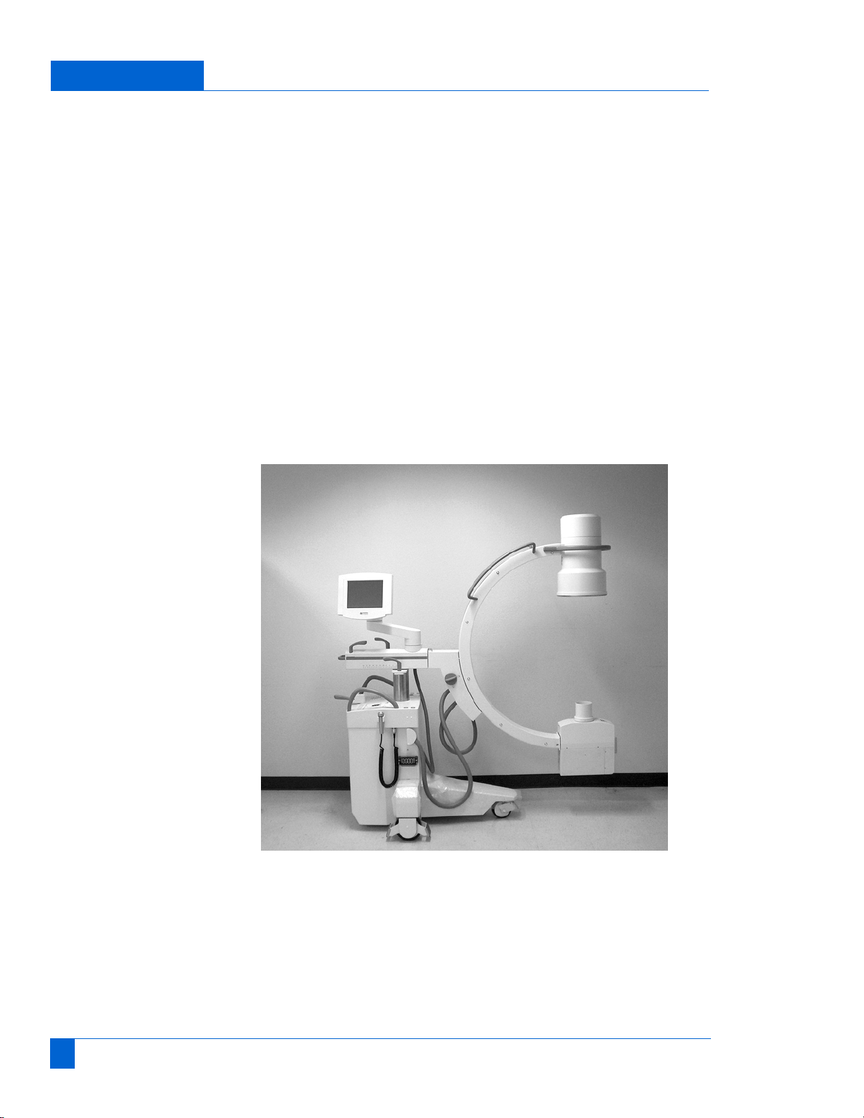
Unpacking the
C-Arm .................................................................................................. 1
Mounting Monitors............................................................................... 2
AC Power Check ................................................................................. 4
Mechanical Movement......................................................................... 5
CDRH Report ...................................................................................... 5
Maintenance Report
Introduction.......................................................................................... 1
Safety .................................................................................................. 2
Documentation .................................................................................... 2
Image intensifier .................................................................................. 2
Labels.................................................................................................. 3
Switch Safety Cutoff .......................................................................... 12
Radiation Indicators........................................................................... 12
Fluoroscopy Time (see 21 CFR 1020.31 (a)).................................... 12
Check kV Values ............................................................................... 12
Check Tube Current .......................................................................... 14
Check Radiographic Tube Current.................................................... 14
Check Reproducibility........................................................................ 15
Beam Quality..................................................................................... 18
Exposure Times................................................................................. 21
Maximum Dose Rate......................................................................... 22
Checking Central X-Ray Beam.......................................................... 23
Adjusting Central X-Ray .................................................................... 25
Tube Head Adjustment...................................................................... 26
Check Collimation.............................................................................. 30
Image Intensifier Format.................................................................... 32
Cassette Format................................................................................ 32
Smallest Field Size............................................................................ 34
Mechanical ........................................................................................ 36
........................................................................................................... 39
Technical data ................................................................................... 39
........................................................................................................... 42
Cleaning, Disinfecting, and Sterilization ............................................ 42

Table of Contents
Page 2 MAN 06-0015: Chapter Rev. A

MAN 06-0015: Rev. A Page 1
ZIEHM VISION INSTALLATION MANUALInstallation
Installation Manual
This Installation Manual supplements the ZIEHM VISION Service
Manual. By no means should installation be attempted without consult-
ing the Service Manual in addition to this Installation Manual.
AudienceThis manual is written to qualified Service Engineers. It does not con-
tain any procedures that can be performed by the System Users. Do
NOT allow System Users to perform any of the service tasks described
in this manual, or any tasks that are not described in the User Manual.
In order to be qualified to perform the Installation procedures described
in this manual, Service Engineers must attend formal training provided
by Instrumentarium Imaging Ziehm. Inc. (hereafter referred to as the
manufacturer).
Unpacking the
C-Arm
Shipping Container
The system is shipped on a single pallet and contains a mobile stand,
monitor cart, case assembly (unmounted), and the items listed in the
table below.
Carefully inspect the equipment for damage. If you find any damage,
immediately report it to the shipping carrier in the form of a damage
claim.
Unpacking
Unpacking of the x-ray system is to be carried out by authorized, quali-
fied personnel.
1. To avoid damage being caused to the equipment by condensation
resulting from temperature differences, make sure that all parts of
the equipment have reached room temperature before turning the
equipment on
2. Remove the outside of the shipping container and inspect.
Item Quantity
User Manual 2
Technical Manual
- C-arm Technical Data
- Approval Certificate
2
Foot Switch 1
Hand Switch 1
Connection Cable 1

ZIEHM VISION INSTALLATION MANUAL: Mounting
Page 2 MAN 06-0015: Rev. A
3. Lower the unloading ramp into position.
4. The Monitor Cart is secured to the pallet by a bracket and four
bolts. Remove the bolts and carefully slide the Monitor Cart off the
pallet.
5. Remove the two straps that hold the monitors and take the monitors
off the pallet.
6. Remove all of the brackets from the pallet.
7. Loosen the Wig-Wag knob and straighten the C-Arm as shown in
Figure 2.1. This will keep the C-Arm from tipping over as it is
removed.
8. Remove the metal brackets that hold the C-Arm mobile stand to the
pallet. Take care not to scratch the mobile stand.
9. Lift the lever located in the center of the control panel (the hand
brake) and carefully move the mobile stand off the pallet and onto
the floor.
2-1: C-Arm in the Transport Position
Mounting Monitors The monitors are the only components that need to be mounted. They
are clearly marked Left and Right (as viewed from the front of the
monitor cart).
1. Remove the monitor’s rear panels.
2. Have a qualified person help you place the monitor assembly onto
the mobile cart’s mounting surface.

MAN 06-0015: Rev. A Page 3
ZIEHM VISION INSTALLATION MANUALInstallation
Caution: Do not attempt to move the monitor assembly by your self.
3. There are four screw holes located on the bottom of the monitor
case. Attach the monitor case to the cart with four allen screws.
4. Route the mobile cart wiring through the hole in the bottom of the
monitor case.
5. Connect the AC power cords and video BNC connectors to their
respective monitors (left and right).
6. Connect the CAN-BUS cables to the RJ45 connector on the CAN
module boards on each monitor.
7. Attach the ground wires to the rear panel and cart.
8. Apply power to the C-Arm and Monitor Cart and verify that the
system works properly. Test All functions. If the system is set-up to
be non-fluoroscopic, then confirm that it cannot produce radiation.
9. Re-attach the rear panels and access plates

ZIEHM VISION INSTALLATION MANUAL: Mounting
Page 4 MAN 06-0015: Rev. A
2-2: .

MAN 06-0015: Rev. A Page 5
ZIEHM VISION INSTALLATION MANUALInstallation
System
Interconnect
The monitor cart and mobile stand are connected with a single, heavy-
duty cable which attaches at the rear of the monitor cart. Connect the
monitor to the monitor cart before turning on the system’s power. Plug
the monitor cart power cord into a properly-rated and grounded power
outlet.
AC Power CheckEnsure that the system’s AC power cord is compatible with the AC
power receptacle. The system must be grounded through the U-shaped
grounding prong of the line.
WARNING: DO NOT use a 3-prong to 2-prong adapter, unless properly
installed by a licensed electrician. Failure to comply may result in seri-
ous or fatal injuries to the System User and other persons in the sur-
rounding area.
Ensure that the AC line voltage is compatible with the power require-
ments of the system. Line voltage must be set to match service. For
voltages above and below 110 VAC (or optional 230 VAC operation),
adjust module 10 line voltage.
Verify power input to the Monitor Cart and adjust Module 10 trans-
former input according to the wall outlet drop-off. For 110 VAC sys-
tems, if the wall outlet idles at 115 VAC and drops to 110 VAC when
the x-ray system produces fluoroscopy at 90 kV, then tap the Monitor
Cart for 110 VAC. For 230 VAC operation, tap to the nearest line volt-
age.
WARNING: Failure to properly set line voltage taps may result in dam-
age to the system’s electronic components.
Check Leakage Current
We recommend that you perform a check of leakage current, using a
calibrated leakage meter, in the following manner:
1. Inspect ground leads to ensure that ground connections are solid.
2. Insert the meter (with 100 ohm input impedance) in series with the
line cord, per the meter manufacturer’s instructions.
3. Turn the meter on and verify that leakage current does not exceed
100 µA, in either normal or reversed line polarity.
4. Connect the black lead of the meter to an exposed metal surface on
the x-ray system.
5. Turn the meter on and verify that leakage current does not exceed
100 µA.

ZIEHM VISION INSTALLATION MANUAL: Mechanical
Page 6 MAN 06-0015: Rev. A
Mechanical
Movement The C-Arm is capable of moving in a 115º arc: 90º from horizontal to
vertical, and 25º beyond the vertical plane; rotating in the vertical plane
around the horizontal cross arm (+225º), or swinging from side-to-side
(+12º). Test C-Arm movement and brakes in the following manner:
1. Release one brake and verify full the full and unrestricted move-
ment of the C-Arm. Secure the brake.
2. Repeat step one for each brake.
3. Release the hand brake on the mobile cart by pulling the handle up,
and check that the cart moves freely and can be steered by turning
the brake/handle.
4. Turn on C-Arm power at the monitor cart control panel. Raise and
lower the C-Arm
2-3: .ON / OFF Keys
Caution: The starting circuit is always powered - even when power is
switched off! To completely disconnect from Mains Power, remove the
power cord from the wall power outlet.
CDRH Report Follow the instructions in the CDRH report and record the results into
the report.

MAN 06-0015: Rev. A Page 7
ZIEHM VISION INSTALLATION MANUALInstallation
This page is intentionally blank.

ZIEHM VISION INSTALLATION MANUAL: CDRH Report
Page 8 MAN 06-0015: Rev. A

Ziehm Imaging, Inc. Vision Installation Manual MAN 06-0015, Rev. A Page 1
Maintenance Report: Introduction
Maintenance Report
This is a master copy of Ziehm’s Maintenance Report for the ZIEHM
VISION C-Arm. Make photocopies and safeguard the original for future
use.
IntroductionYou are required by the Food and Drug Administration (FDA) to perform the checks
and inspections described in this document, at least every six months. This is to ensure
that the x-ray system complies with federal regulations (specifically, the applicable
sections of CFR 21, Subchapter J - Radiological Health).
Responsibilities
The equipment user is responsible for ensuring that the maintenance steps described
in this procedure are performed every six months. Failure to comply with this require-
ment relieves the manufacturer and his agents of all responsibility in this matter.
The equipment user is responsible for ensuring that only service technicians certified
by the manufacturer perform the tests and adjustments described in this procedure.
Service technicians are responsible for performing this procedure in the manner
described in this document.
Company Information
Please provide the following information:
Required Equipment
The following equipment and material is required to perform this procedure:
1. Digital multi meter (e.g., Fluke 8040A, or Fluke 87)
2. Dosimeter kit
3. Beam center target, 40-400-T10
4. Storage oscilloscope
5. Fluorescent cross, 44-14-538 RH090
6. Vinyl lead sheets (3 mm lead blocker)
7. Maintenance Record
Company Name:
Phone Number:
Address:
C-Arm Serial Number:
Location/Room Number:
Name of Technician:

Ziehm Imaging, Inc. Vision Installation Manual MAN 06-0015, Rev. A Page 2
Maintenance Report: Safety
SafetyThroughout this procedure you will be required to measure several equipment operat-
ing values and record your measurements.
Checks or adjustments that require radiation exposure are marked with the radiation
symbol displayed on the right, to alert you to follow all applicable safety codes and
regulations.
CAUTION: Follow all safety rules regarding the use of radiation-emitting
equipment including the following:
1. Make all earth-lead connections provided by the manufacturer. For example,
equipment metal panels may expose you to dangerous voltages, unless they are
grounded. Therefore, ground metal panels.
2. Use a digital multi meter to check each ground lead connection. Measure from
ground point to outside cover, to ensure that positive grounding has been
achieved.
3. Follow all local occupational safety laws and state codes that pertain to your
installation site.
4. If an accident occurs, or if there are hazards which may result in an accident,
immediately notify your supervisor.
5. Make sure that you raise the C-Arm high enough to allow the C to rotate freely
without interference from the C-Arm base or floor. Verify that the C-Arm is high
enough and that the control locks work properly with the C in various positions.
Ensure that there are no objects which may impede the free movement of the C-
Arm.
DocumentationVerify that the following documents were delivered to the customer.
If the customer cannot locate either of these documents, arrange to have the missing
documents replaced immediately.
Image intensifierVisually inspect the image intensifier to determine if there are any mechanical faults
(e.g., broken or missing covers). If there is a mechanical fault, write a description of the
fault below and contact Ziehm Imaging, Inc.
_____________________________________________________________________
_____________________________________________________________________
_____________________________________________________________________
_____________________________________________________________________
_____________________________________________________________________
_____________________________________________________________________
Document Documents Received?
Operating Instructions Yes No
Maintenance Instructions Yes No

Ziehm Imaging, Inc. Vision Installation Manual MAN 06-0015, Rev. A Page 3
Maintenance Report: Labels
Labels
Fig. 1 Labels on the C-arm stand (USA)
Fig. 2 Labels on systems with laser aiming device on the image intensifier
(left) and on the generator (right) - USA
1
9
11&12
2&4
13
34
29
13
6
30
31
33
32
8
35
7
14
14 15
16
17
17
15
14
16
18
Keep Out
Radiatio n
ControlArea 1m
CircleDistance4m
MANUFACTURED: MONTH: O CTO BER YEAR:2001
MANUFACTUREDBY:
ZIEHMIMAGING GMBH
D-90451NU RN BERG -ISARSTSSE 40 GERMANY
COMPLIES WI TH CD RH RADIATION PERFORMANCE
STANDARDS,21CFRSUBCHAPTERJ.ASOFDATE
OFMANUFACT U RE
C
ZiehmVision
SERIALNo.
ZV-3774
1275
MobileStand
21CFRS UBCHAPTER JSECTION1020.32;
14
15
815 14
18
17
17
16
18

Ziehm Imaging, Inc. Vision Installation Manual MAN 06-0015, Rev. A Page 4
Maintenance Report: Labels
Fig. 3 Labels on the Ziehm Vision monitor cart (USA)
Fig. 4 Labels on a Ziehm Vision monitor cart with flat screens (USA)
2.
LINEVOLTAGE: 12 0 va c 60 Hz
LINEIMPEDA NCE : <=0.6ohm
CURRENTINPUT 10AContinuos/20AMomentary
20A,250V
MAINFUSE:
C
VISIONMC
SERIALNo.
MC-3774
1275
MonitorCart
MANUFACTURED:MONTH:O CTOBER YEAR: 2001
MANUFACTUREDBY:
ZIEHMIMAGING GMBH
D-90451 NUR NBE RG - IS AR STS SE 40 GE RMAN Y
27
26
25
10
22
DICOM
DICOM
TX RX
23
28
Warning:
Forcontinuedprotectionagainst
riskoffire.Replaceonlywiththe
same type and ra ting of fuse.
20
19
2
4
28
DICOM
DICOM
27 26
25
10
22
2
3
28
20
19
24
28
LINEV O LT AG E: 120vac60 Hz
LINEIMP E DAN C E: <=0. 6 oh m
CURRENTINPUT 10AContinuos/20AMomentary
20A,250V
MAINFUSE:
C
VISIONMC
SERIALNo.
MC-3774
1275
MonitorCart
MANUFACTURE D : MONTH: OCTOBER YE AR:2001
MANUFACTUREDBY:
ZIEHMIMAGINGGMBH
D-90451NURNBERG-ISARSTSSE 40 GERMANY
Warning:
Forcontinuedprotectionagainst
risk of f ire. R epla ce onl y with t he
sametypeand ratingof fuse.

Ziehm Imaging, Inc. Vision Installation Manual MAN 06-0015, Rev. A Page 5
Maintenance Report: Labels
No. Label Comments Present &
Legible?
1—
2—
3—
4—
5—
6—
Table 1 Labels on the Ziehm Vision (USA)
THISX-RAYUNITMAYBEDANGEROUSTO
PATIENT AND OPERATOR UNLESS SAFE
EXPOSURE FACTORS AND OPERATING
INSTRUCTIONSAREOBSERVED.
Cet appareil de radiographie peut presenter
des dangers pour le patient etl’operateur si les
facteurs d’exposition en securite et les
instructionsd’utilisationnesontpasrespectes.
EXPLOSION HAZARD!
DO NOT USE IN PRESENCE OF
FLAMMABLE ANESTHETICS.
RISQUE D’EXPLOSION!
NE PAS UTILISER EN PRESENCE
DE PRODUITSANESTHESIANTS.

Ziehm Imaging, Inc. Vision Installation Manual MAN 06-0015, Rev. A Page 6
Maintenance Report: Labels
7—
8—
9—
10 Please observe
accompanying documents!
11 —
12 —
13 —
14 Only on systems with laser
aiming device
15 Only on systems with laser
aiming device
Table 1 Labels on the Ziehm Vision (USA)
Keep Out
Radiation
Control Area 1m
Circle Distance 4m
CAUTION
LASER RADIATION-DO NOT
STARE INTO BEAM
PEAK POWER: 1mW
WAVELENGTH: 5nm
CLASS II LASER PRODUCT
63

Ziehm Imaging, Inc. Vision Installation Manual MAN 06-0015, Rev. A Page 7
Maintenance Report: Labels
16 Only on systems with laser
aiming device
17 Only on systems with laser
aiming device
18 Only on systems with laser
aiming device
19a —
Table 1 Labels on the Ziehm Vision (USA)
LASER
APERTURE
Table of contents
Popular Medical Equipment manuals by other brands

Cliq
Cliq TC-2000v manual

Boston Scientific
Boston Scientific Precision Connector M1 Directions for use

Ferno
Ferno Pedi-Mate 678 user manual

Ferno
Ferno Multi-Stretcher Pedi-Mate BRH-678-MS user manual

Pari
Pari LC SPRINT SINUS Instructions for use

Stryker Medical
Stryker Medical RUGGED 6080 MX-PRO Operation & maintenance manual