ZipRip UC5 User manual

Printer Controller Unit
(UC5)

Trademarks
Microsoft®, Windows®, and MS-DOS®are registered trademarks of Microsoft
Corporation in the United States and /or other countries.
Other product names used herein are for identification purposes only and may be
trademarks of their respective companies. We disclaim any and all rights involved
with those marks.
Symbols
This manual uses several symbols. The meanings of those symbols are as follows:
☛See or Refer to
!Clip ring
"E-ring
#Screw
$Connector

TABLE OF CONTENTS
1. INSTALLATION ..................................................................... UC5-1
2. REPLACEMENT AND ADJUSTMENT................................... UC5-2
2.1 CONTROLLER BOARD MEMORY....................................................... UC5-2
2.2 VIDEO I/F BOARD................................................................................ UC5-3
2.3 LOAD PROGRAM................................................................................. UC5-4
2.4 TEST PAGE.......................................................................................... UC5-5
3. TROUBLESHOOTING ........................................................... UC5-6
3.1 TROUBLESHOOTING FLOWCHART .................................................. UC5-6
3.2 LED STATUS LIGHT SEQUENCE AND CONDITIONS ....................... UC5-7
3.2.1 POWER ON AND ACTIVATION.................................................. UC5-7
3.2.2 TEST PAGE BUTTON................................................................. UC5-8
3.3 PRINTER DRIVER OPERATION.......................................................... UC5-9
4. SERVICE TABLE ................................................................... UC5-9
5. DETAILED DESCRIPTIONS ................................................ UC5-10
5.1 OVERVIEW ........................................................................................ UC5-10
5.2 MACHINE LAYOUT ............................................................................ UC5-11
6. SEPECIFICATIONS ............................................................. UC5-12
29 August, 2003 CONTROLLER BOARD MEMORY
UC5-1
1. INSTALLATION
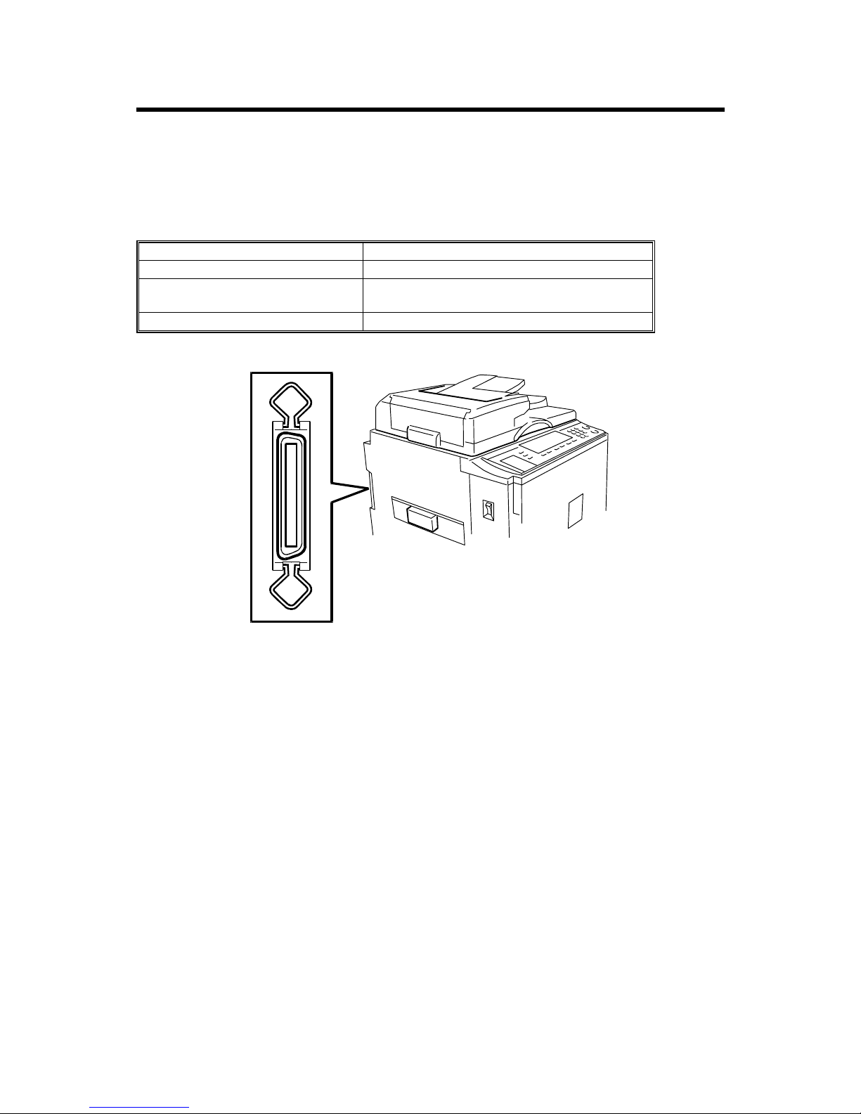
The HP4 for China (HP4P) is equipped with a standard printer controller unit and
Video I/F board. Connect the printer controller unit to the host computer with a
parallel cable. Then install the printer driver in the host computer.
Host computer IBM PC/AT compatible PC
Interface IEEE1284B (Compatible, Nibble, ECP)
Operating Systems Supported Windows 95/98/Me, Windows NT4.0,
Windows 2000/XP
Printer Driver Digital Duplicator A3 400 GDI
C249I950.WMF
CONTROLLER BOARD MEMORY 29 August, 2003
UC5-2
2. REPLACEMENT AND ADJUSTMENT
!CAUTION
Before removing any of the controller components, do the following:
1. If the ‘data-in’ lamp on the operation panel is blinking or lit, wait until the
document or report is printed. Then turn off the machine.
2. Turn off the main switch and disconnect the power cord, and the cable.
NOTE: This manual uses these symbols:
Screw: #Connector: $
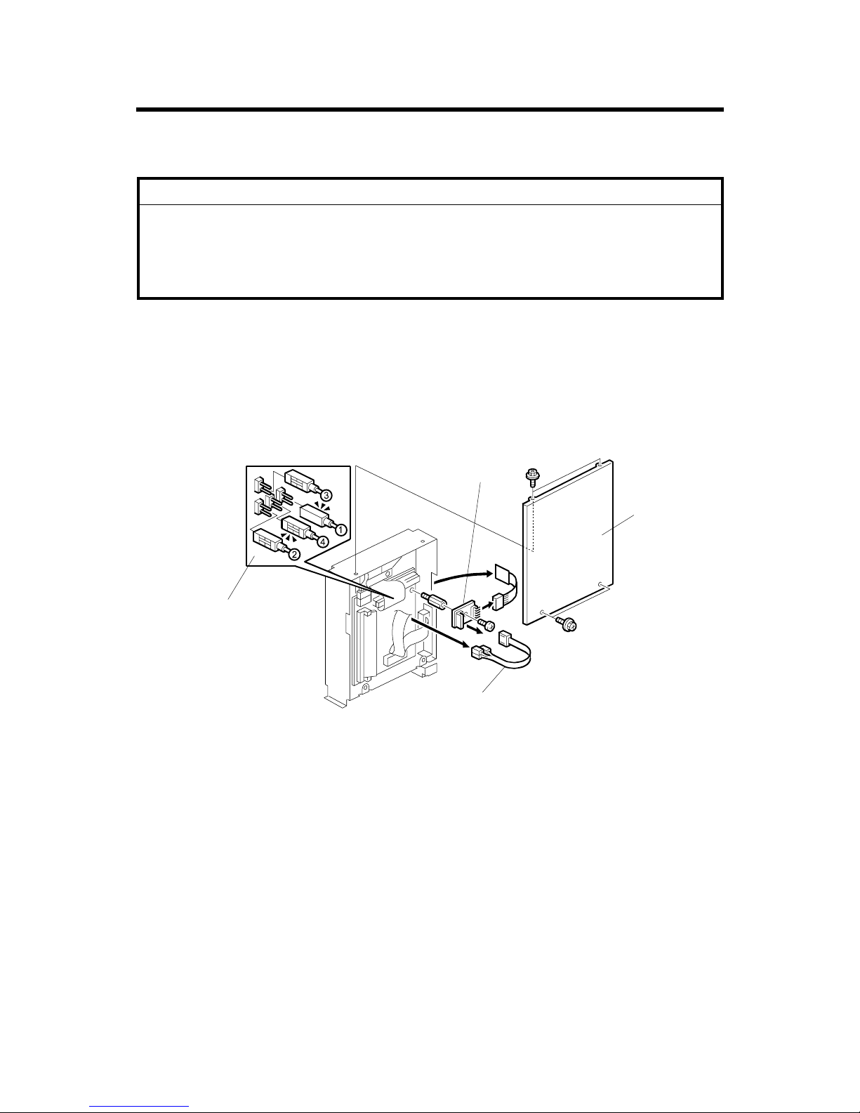
2.1 CONTROLLER BOARD MEMORY
[A]: Cover
[B]: Keypad board
NOTE: When you attach the connector [C] make sure to attach it in the correct
direction and position [D].
C249R951.WMF
[A]
[B]
[D]
[C]
29 August, 2003 VIDEO I/F BOARD
UC5-3
[A]: Connector
[B]: Printer controller board
[C]: SIMM module
NOTE: The twisted portion of the harness [D] should fit loosely and close to the
controller board.
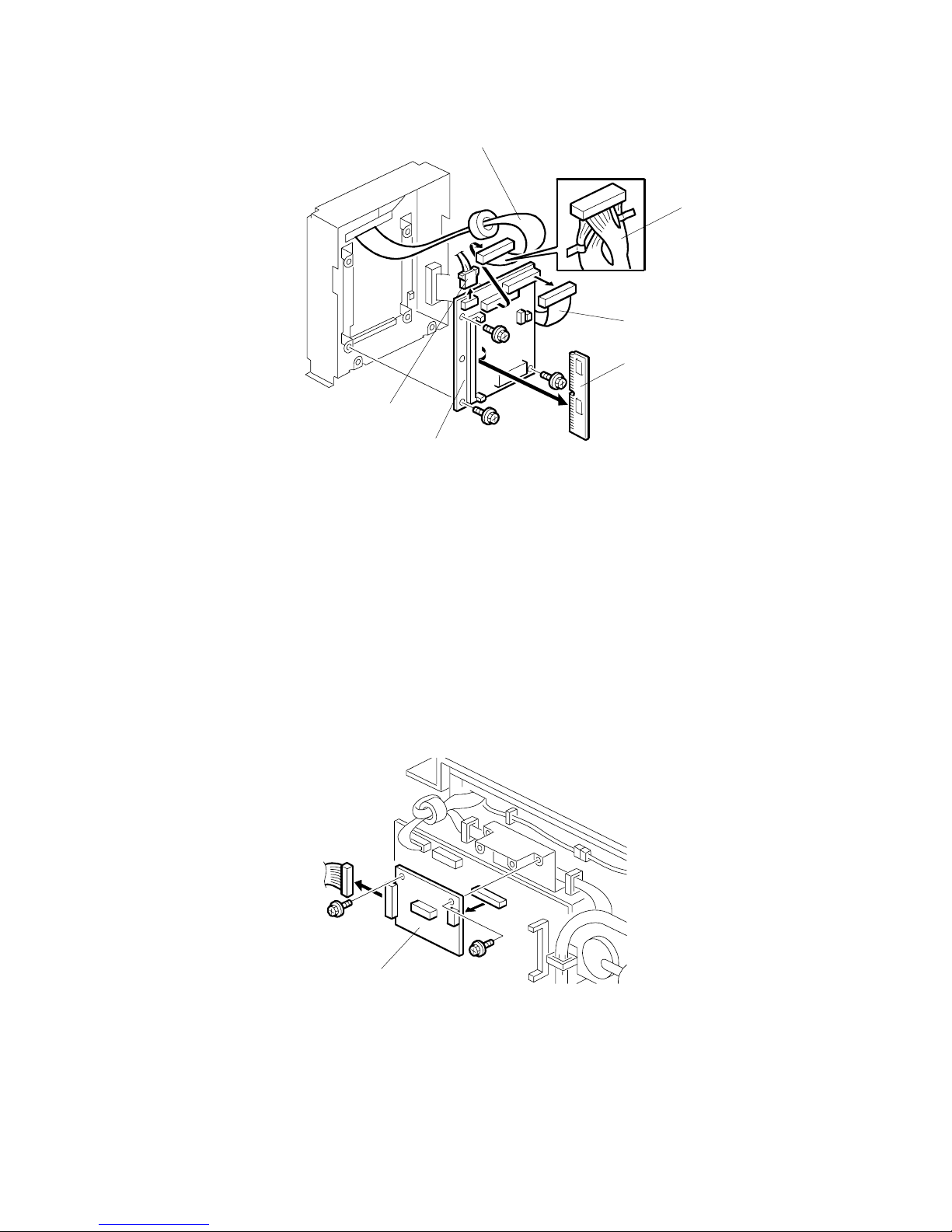
2.2 VIDEO I/F BOARD
[A]: Video I/F Board
C249R952.WMF
C249R953.WMF
[A]
[A]
[A]
[A]
[B]
[C]
[D]
LOAD PROGRAM 29 August, 2003
UC5-4
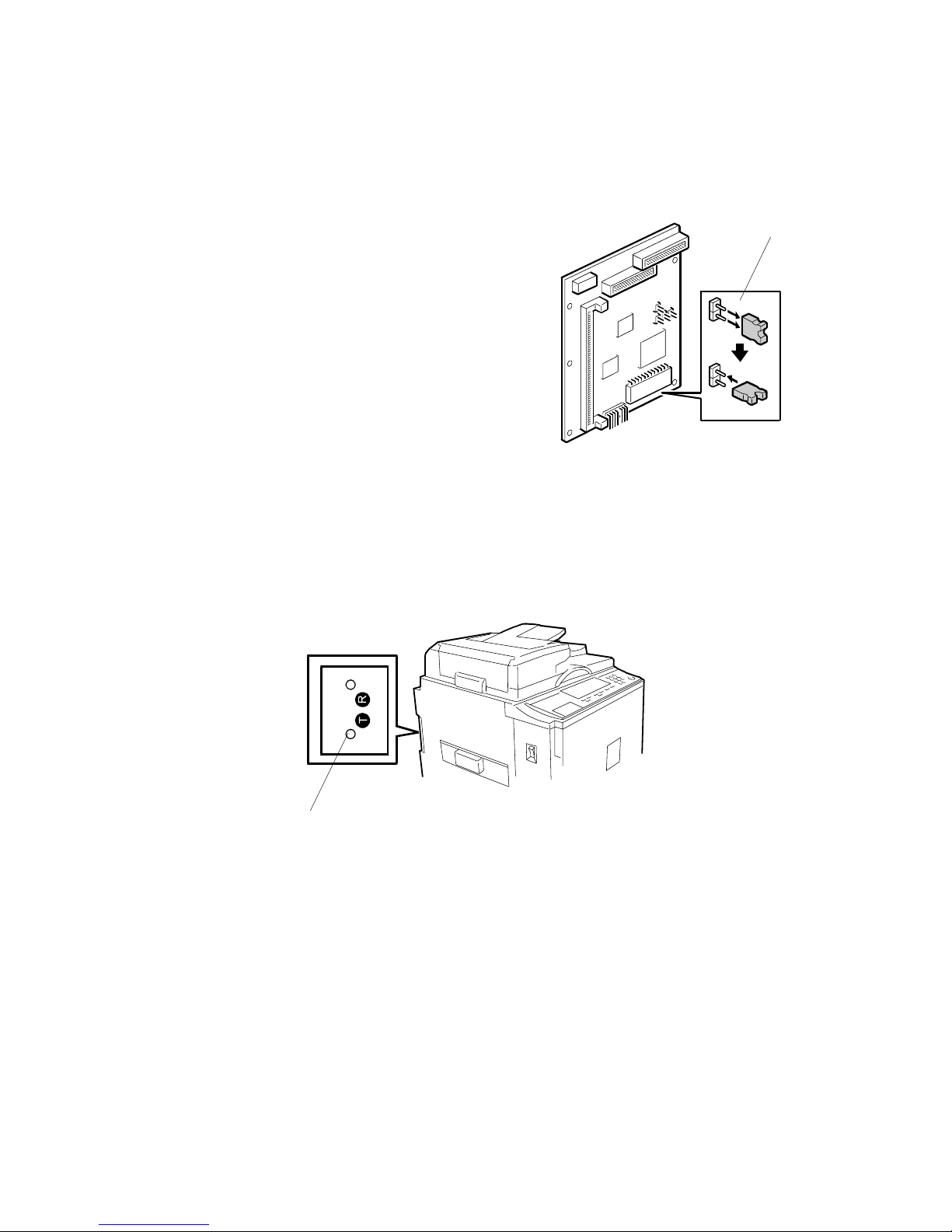
2.3 LOAD PROGRAM
This procedure is for upgrading the system firmware for the controller.
NOTE: If the controller does not start up after a firmware update, try to download
the firmware again. If it still does not work, you may need to replace the
flash ROM on the printer controller board.
!CAUTION
Do not turn off the machine while downloading the firmware.
1. Before downloading new firmware, print the test page. Then check the current
version. (☛2.6)
2. Turn off the machine.
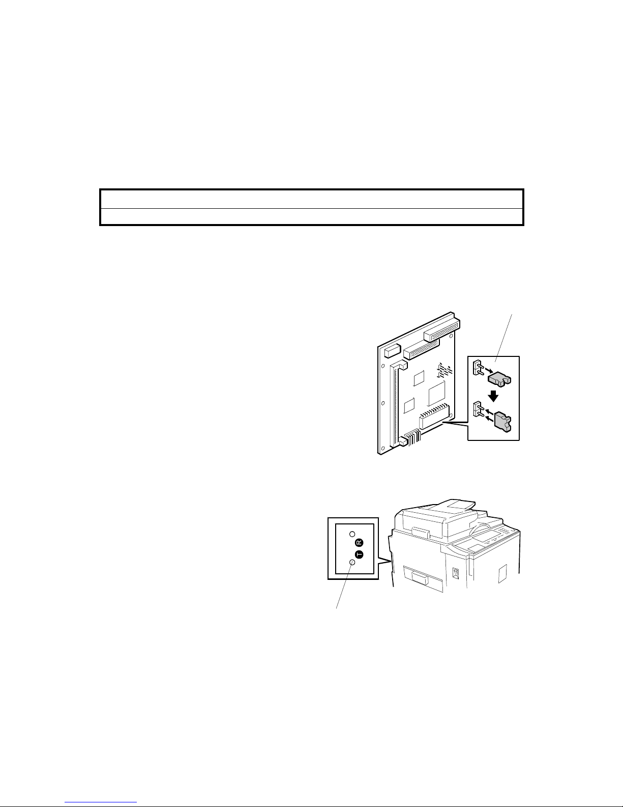
3. Remove the rear cover and the controller cover.
4. Put the jumper next to the flash ROM into the
position [A].
5. Turn on the machine.
6. Boot up the PC and access the MS-DOS prompt
or Command Prompt.
7. Use COPY command to update the flash ROM.
e.g. “copy file_name LPT1:” LPT1 is the
connected port.
8. While the flash ROM is updating, the
left LED [B] on the control button
board is continuously on.
C249R957.WMF
C249R954.WMF
[B]
[A]
29 August, 2003 TEST PAGE
UC5-5
9. When the left LED flashes rapidly, the process has completed.
10. Turn off the machine.
11. Put the jumper into the off position [C] next to
the flash ROM.
12. Turn on the machine and print the test page
pressing the test page button. Then check
the new version.
2.4 TEST PAGE
Press the test page button [A] on the keypad board. The right LED will start to flash
quickly. This indicates that the controller is in the process of creating the test page.
C249R958.WMF
C249R954.WMF
[A]
[C]
TROUBLESHOOTING FLOWCHART 29 August, 2003
UC5-6
3. TROUBLESHOOTING
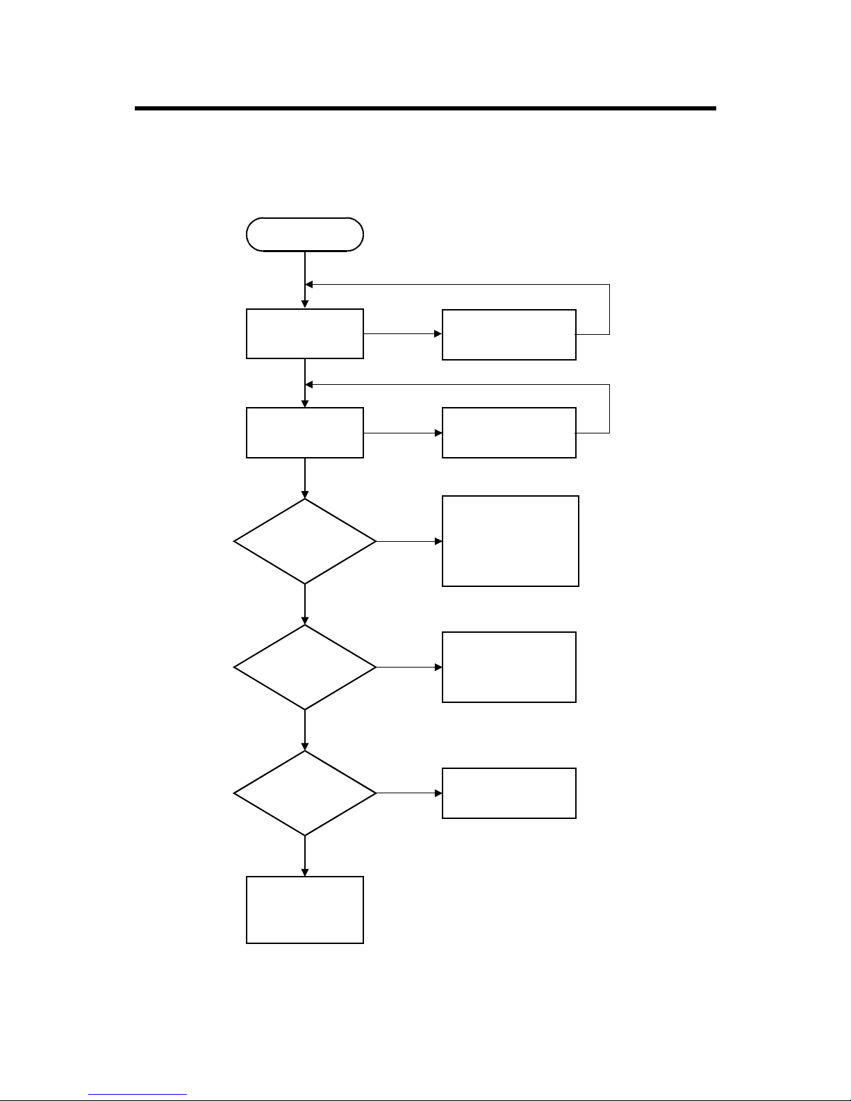
3.1 TROUBLESHOOTING FLOWCHART
Problem
Engine works
normally
LED status is
normal
Test page is
printed normal
Is print test
result normal?
Printed normal
with DOS
Printer Port of
Computer, Printer
Cable
Recover from the
error
Recover from the
error
!Controller Board
!Program ROM
!Video Cable
!Video I/F Board
!Cable
Printer Driver
Setting, or
Application
Software Setting.
Printer Driver Fault
Yes
Yes
Yes
No
No
Yes
Yes
No
No
No
C249T950.WMF
29 August, 2003 LED STATUS LIGHT SEQUENCE AND CONDITIONS
UC5-7
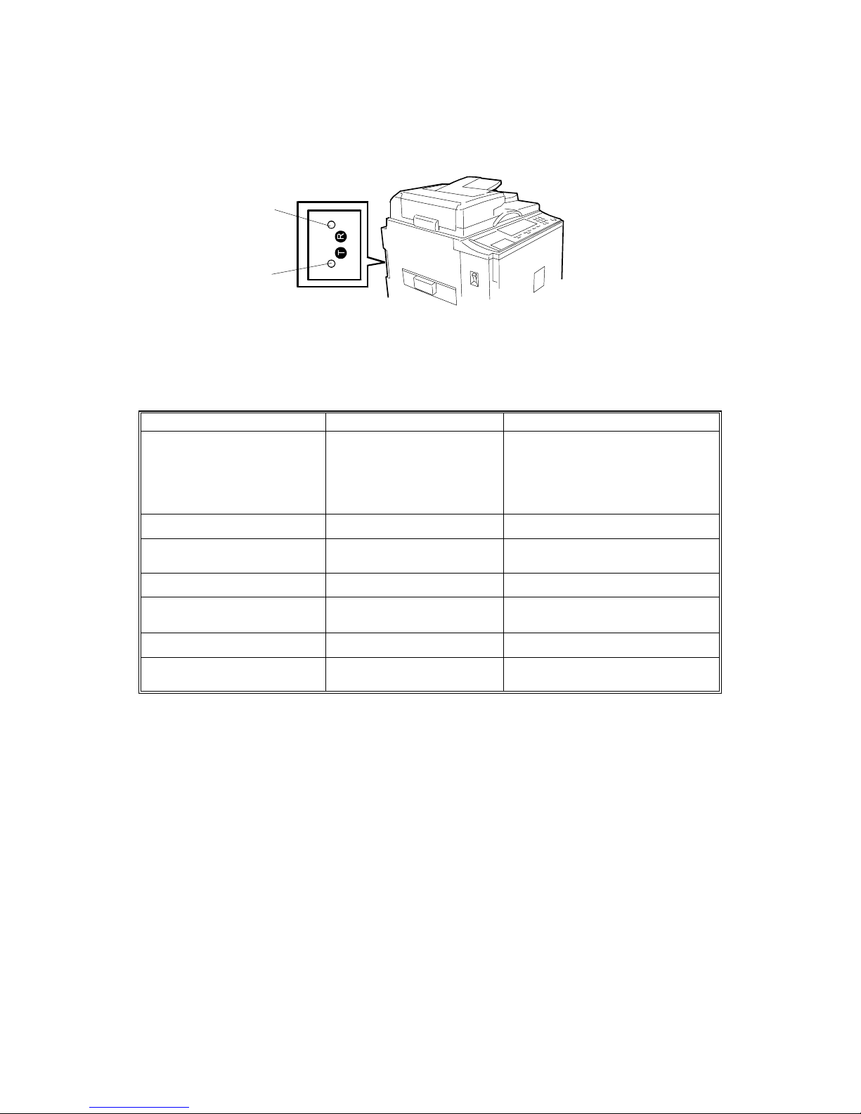
3.2 LED STATUS LIGHT SEQUENCE AND CONDITIONS
3.2.1 POWER ON AND ACTIVATION
STATUS CONTENTS CHECK POINT
All LEDs are off No power supply • No AC power.
• AC cord not properly
connected.
• Power supply failure in the
controller.
Right LED is on Power on -
Left LED is flashing Self-diagnostic test before
ready -
Left LED is flashing rapidly Receiving data -
Left LED is on continuously Transferring data
Making a master
-
Left LED is continuously off Idle -
Left LED flashing slowly
and evenly
Error on engine • Check message on operation
panel.
C249T951.WMF
Left LED
Right LED
Other manuals for UC5
1
Table of contents


