Zoeller 4000 Series User manual

TO AVOID SERIOUS OR FATAL PERSONAL INJURY OR MAJOR
PROPERTY DAMAGE, READ AND FOLLOW ALL SAFETY
INSTRUCTIONS IN MANUAL AND ON VALVE.
THISMANUALISINTENDEDTOASSISTINTHEINSTALLATION
AND OPERATION OF THIS UNIT AND MUST BE KEPT WITH
THE VALVE.
This is a SAFETY ALERT SYMBOL.
When you see this symbol on the valve or in
the manual, look for one of the following signal
words and be alert to the potential for personal
injury or property damage.
Warns of hazards that WILL cause serious
personal injury,deathormajorpropertydamage.
Warns of hazards that CAN cause serious
personalinjury,deathormajorpropertydamage.
Warns of hazards that CAN cause personal
injury or property damage.
Indicates special instructions which are very
important and must be followed.
THOROUGHLY REVIEW ALL INSTRUCTIONS AND
WARNINGS PRIOR TO PERFORMING ANY WORK ON THIS
VALVE.
MAINTAIN ALL SAFETY DECALS.
Product information presented
here reects conditions at time
of publication. Consult factory
regarding discrepancies or
inconsistencies.
MAIL TO: P.O. BOX 16347 • Louisville, KY 40256-0347
SHIP TO: 3649 Cane Run Road • Louisville, KY 40211-1961
TEL: (502) 778-2731 • 1 (800) 928-PUMP • FAX: (502) 774-3624
Visit our website:
zoellerpumps.com
© Copyright 2021. All rights reserved.
SECTION: C4.00.120
CL0161
0321
Supersedes
0515
4000 Series Automatic Multizone Valve
OWNER'S MANUAL
Congratulations on the purchase of the Zoeller Pump Company
4000 Series Automatic Multizone Valve. High quality workmanship
and easy maintenance design has been incorporated into this line
of onsite wastewater products. This Zoeller Pump Company product
will provide years of trouble-free service when installed according
to the manufacturers recommendations.
This manual incorporates the installation, operation, maintenance,
and service instructions into one document to aid the owner of a Zoeller
PumpCompanyonsitewastewaterproduct.Please read andreviewthis
manualbeforeinstallingtheproduct.Theinstructionscontained herein,
when followed correctly, will not only ensure a long and problem-free
life for the system, but will also save time and money during installation.
Should further assistance be necessary please call 1-800-928-7867.
Owner’s Information
Part Number: ______________ Date Code: _________
Job Name: ______________________________________
Dealer: _________________________________________
Date of Purchase: ________________________________
Contractor:______________________________________
Date of Installation: ______________________________
Safety Instructions ........................................................................1
Limited Warranty...........................................................................2
Major Components........................................................................2
Cam Replacement Instructions...................................................2
Valve Installation Instructions ............................................... 2-3
Technical Specifications.............................................................3
Parts List..........................................................................................4
Troubleshooting and Service Checklist ...................................4
Table of Contents Safety Instructions
CAUTION
Register your
Zoeller Pump Company Product
on our website:
http://reg.zoellerpumps.com/

2
© Copyright 2021. All rights reserved.
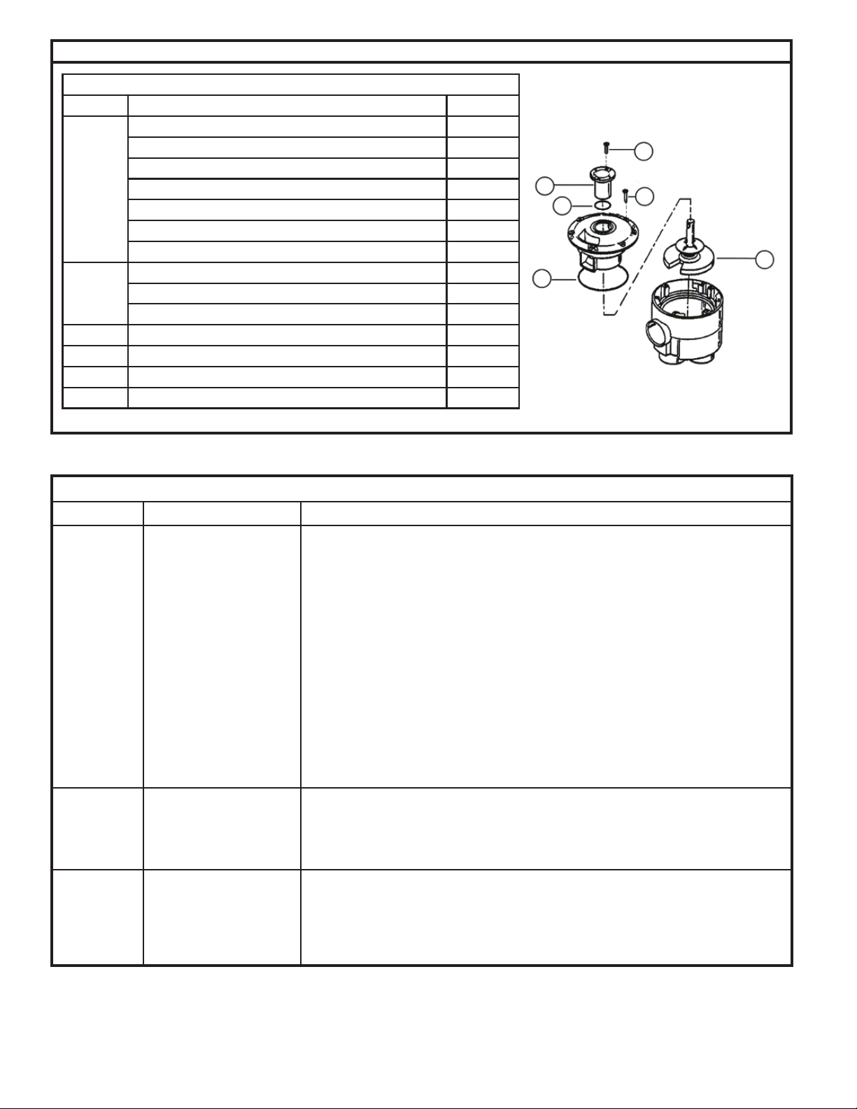
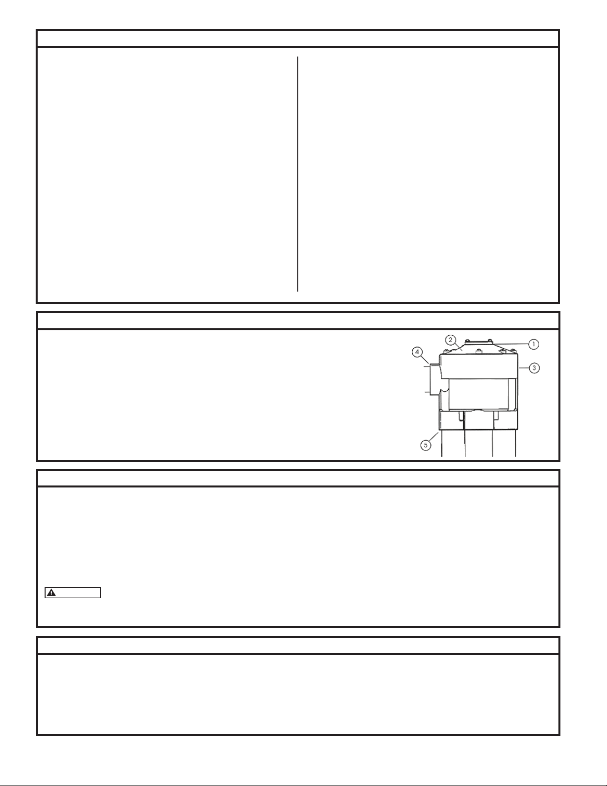
1. Cam - Used to index the valve to the next zone and controls how many outlets are to be used. May
be changed to increase or decrease number of operating zones. Secured to valve top with two cam
retaining screws.
2. Valve Top - A high strength ABS plastic top secured with seven valve top retaining screws.
3. Valve Body - A high strength ABS plastic housing.
4. Inlet - Allows for slip and glue connection of a 1-1/4' pipe.
5. Outlets - 4 outlet model - 1-1/4 PVC pipe / 6 outlet model 1' PVC pipe.
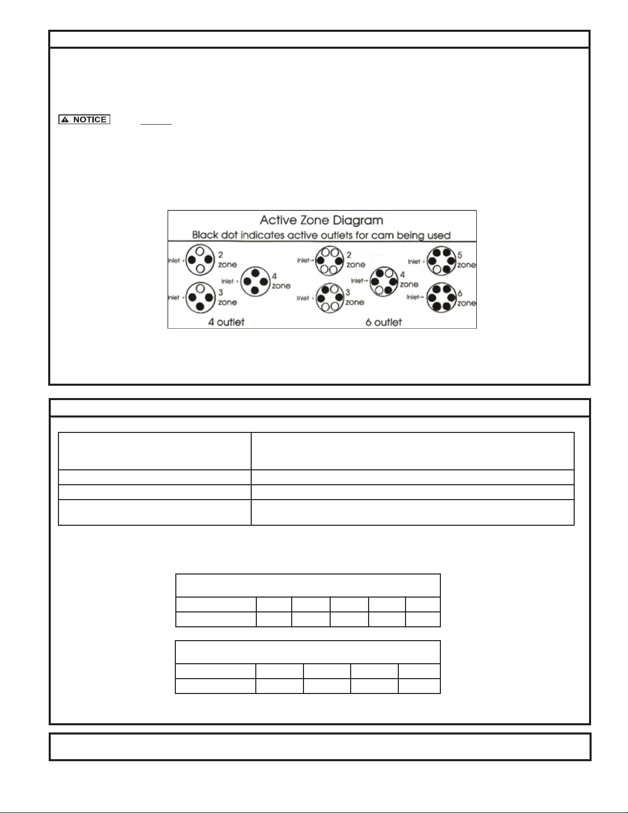
Replacement cams are available to increase or decrease the number of operating outlets on the 4000 Series Automatic Multizone Valve.
BE SURE YOU HAVE THE CORRECT REPLACEMENT CAM. Except for the two zone cam, cams for the four outlet valves and the six outlet valves are NOT inter-
changeable. The correct bottom to be used is marked on the top of the cam.
To remove cam, remove two cam retaining screws and pry up gently with screwdriver.
To install a new cam, partially insert the cam into the valve top and rotate it counterclockwise while applying gentle downward pressure. This allows the upper
lug on the stem in the valve to slip into the cam. The cam should slip into place easily. When installed correctly, the cam should slide down in place with NO
tendency to spring back. Improper installation will cause the valve to jam and prevent the valve from advancing properly.
CAUTION
Cams for operation of fewer than the full number of outlets have one or more camming slots blocked. Because of this, it is important to
make sure that the cam is lowered in the valve so that the lug on the stem in the valve is inserted into an open cam slot in the cam.
Prior to installation of 4000 Series Automatic Multizone Valve, make sure that the system is designed using adequate pipe sizes to ensure maximum perfor-
mance of the valve.
For installation with large terrain elevations, or applications with high lift requirements, the valve should be installed at the highest point in the system, or
check-valves should be installed near the valve in the elevated lines to prevent the back ow of water from the higher locations to the lower zones.
Limited Warranty
Manufacturer warrants, to the purchaser and subsequent owner during
the warranty period, every new product to be free from defects in material
and workmanship under normal use and service, when properly used and
maintained, for a period of one year from date of purchase by the end user, or
18 months from date of original manufacture of the product, whichever comes
rst. Parts that fail within the warranty period, one year from date of purchase
by the end user, or 18 months from the date of original manufacture of the
product, whichever comes rst, that inspections determine to be defective
in material or workmanship, will be repaired, replaced or remanufactured
at manufacturer's option, provided however, that by so doing we will not be
obligatedtoreplace anentireassembly,theentire mechanismor thecomplete
unit. No allowance will be made for shipping charges, damages, labor or
other charges that may occur due to product failure, repair or replacement.
Thiswarranty does not apply to and there shall be no warrantyfor any material
orproductthathas beendisassembledwithoutprior approvalofmanufacturer,
subjected to misuse, misapplication, neglect, alteration, accident or act of
God; that has not been installed, operated or maintained in accordance with
manufacturer's installation instructions; that has been exposed to outside
substances including but not limited to the following: sand, gravel, cement,
mud,tar, hydrocarbons, hydrocarbonderivatives (oil, gasoline, solvents, etc.),
or other abrasive or corrosive substances, wash towels or feminine sanitary
products, etc. in all applications other than in efuent pumping applications.
The warranty set out in the paragraph above is in lieu of all other warranties
expressed or implied; and we do not authorize any representative or other
person to assume for us any other liability in connection with our products.
Contact manufacturer at, 3649 Cane Run Road, Louisville, Kentucky 40211,
Attention: Customer Support Department to obtain any needed repair or
replacement of part(s) or additional information pertaining to our warranty.
MANUFACTURER EXPRESSLY DISCLAIMS LIABILITY FOR SPECIAL,
CONSEQUENTIAL OR INCIDENTAL DAMAGES OR BREACH OF EXPRESSED
OR IMPLIED WARRANTY; AND ANY IMPLIED WARRANTY OF FITNESS FOR
A PARTICULAR PURPOSE AND OF MERCHANTABILITY SHALL BE LIMITED
TO THE DURATION OF THE EXPRESSED WARRANTY.
Some states do not allow limitations on the duration of an implied warranty,
so the above limitation may not apply to you. Some states do not allow the
exclusion or limitation of incidental or consequential damages, so the above
limitation or exclusion may not apply to you.
This warranty gives you specic legal rights and you may also have other
rights which vary from state to state.
Major Components
Cam Replacement Instructions
Valve Installation Instructions

3
© Copyright 2021. All rights reserved.
Pump Fed Applications:
The 4000 Series Automatic Multizone Valve can be installed directly off the discharge side of the pump. The valve is cycled as the pump is turned off and on. It
is important to install the valve as close to the pump as possible.
The 4000 Series Automatic Mulitzone Valve may be installed below ground in a valve box.
Valve MUST BE at the highest point in your system.
When connecting the lines to the valve outlets, ensure that the correct cam is installed. Install lines to outlets corresponding to the numbers on the cam. See
diagram for proper zone hookup of outlets.
Do NOT turn the valve upside down when gluing the inlet and outlet lines into the valve as glue may run down into the valve and interfere with proper operation.
Allow glue to dry for at least two hours before operating or testing the valve. For best results, use a multi-purpose glue.
Valve Installation Instructions, continued
Technical Specifications
Flow Characteristics:
Flow Range: 10-50 GPM on 4400 Series
10-40 GPM on 4600 Series
Stem and disk assembly for lower ows available. (See parts list).
Valve Top and Body Construction: High strength ABS plastic.
Inlet: Slip and glue connection to a 1-1/4" PVC pipe.
Outlets: 4 outlet accepts 1-1/4" PVC pipe with slip and glue connection.
6 outlet accepts 1" PVC pipe with slip and glue connection.
4400 Series 4 Outlet Valve
Flow (GPM) 10 20 30 40 50
Pressure (PSI) 2.0 3.0 4.5 6.4 10.0
4600 Series 6 Outlet Valve
Flow (GPM) 10 20 30 40
Pressure (PSI) 2.5 4.5 7.5 11.5
To seal off any unused outlets, install a piece of PVC pipe at least six inches in length to the outlet and cap the pipe. This will allow additional zones
to be used.
All Zoeller Pump Company products must be installed and maintained in accordance with all applicable codes.
Product information presented here reects conditions at time of publication. Consult factory regarding discrepancies or inconsistencies.

4
© Copyright 2021. All rights reserved.
4
1
3
6
5
2
Parts List
REF NO. DESCRIPTION PART NO.
1
Two zone for four or six outlet valve 153276
Three zone cam for four outlet valve 019586
Four zone cam for four outlet valve 019938
Three zone cam for six outlet valve 153277
Four zone cam for six outlet valve 153278
Five zone cam for six outlet valve 153279
Six zone cam for six outlet valve 152185
2
Stem / disk assy. w/ .028 spring (white) 151236
Light stem / disk assy. w/ .025 spring (blue) 152518
Heavy stem / disk assy. w/ .032 spring (red) 153280
3 Valve top retaining screw set (7)(10x1 Phil Pan SS) 153281
4 Cam retaining screw set (2)(10-24x3/4 Phil Pan SS) 153282
5 Valve Top O-ring 153283
6 Cam O-ring 153284
Parts List
Troubleshooting and Service Checklist
Problem Cause Solution
Valve does
not change or
cycle to next
zone or outlet.
The stem and disk assembly
is not rotating when the
water ow is turned OFF and
then back ON.
• Ensure there is no debris inside the cam. Clean and carefully reinstall the cam.
• If fewer than the maximum number of outlets are being used, check the installation of
the cam. Ensure that the stem and disk assembly is not being held down by an improperly
installed cam. Refer to the Cam Replacement Instructions.
• Remove the valve top and check for proper movement of stem and disk assembly. Check
for and remove any debris or foreign objects that may jam or retard the movement of the
disk.
• Check for freedom of movement of stem and disk assembly up and down over the center
pin in bottom of valve. Scale deposits may build up on the pin and hold stem and disk
assembly down. Clean pin and again check for freedom of movement.
• Be sure that all operating outlets are not capped and that the ow to operating zones is
not restricted in any manner. This would cause pressure to build up in the valve and lock
the stem and disk assembly in the down position.
• The back ow of water from uphill lines may be preventing the valve from cycling properly.
If the valve cannot be placed close to the high point of the system, a check valve should
be installed near the valve in the outlet line that runs uphill from the valve.
Water comes
out of all the
valve outlets.
Stem and disk assembly not
seating properly on valve
outlet.
• Check for sufcient water ow. A minimum of 10 GPM is required to properly seat the disk.
For water ow between 6 and 10 GPM, a stem and disk assembly with a lighter spring is
available.
• Remove the valve top and check the inside walls to ensure that nothing is interfering with
the up and down movement of the stem and disk assembly inside the valve.
Valve skips out-
lets or zones.
This will cause the valve to
cycle quickly several times,
skipping one or more zones.
The ow should be steady
and uninterrupted.
• The stem and disk assembly is being advanced past the desired outlet.
• Ensure that the correct cam for the desired number of zones is installed and that the
outlet lines are installed to the correct outlet ports of the valves as indicated by the zone
numbers on the top of the cam.
Table of contents