Zoeller APak 10-4014 User manual

© Copyright 2018 Zoeller®Co. All rights reserved.
1
For indoor use only.
All electrical and safety codes must be followed including the National Electrical Code and all applicable local codes.
Do not connect powered devices to inputs.
SPECIFICATIONS
This alarm unit monitors liquid levels in lift pump chambers, sump pump basins, holding tanks, and other non-potable water applications. In addition, the Z
Control®Enabled version of the APak®can connect to the Z Control®Cloud with its built-in Wi-Fi®. It features a green Power On LED, red Input 1 and Input 2
LEDs, an audible buzzer, normally closed dry contacts, and a Silence/Reset/Test button. The APak®plugs into a 120 V, 60 Hz receptacle. Battery backup power is
applied by 2 standard alkaline AA batteries, which are not included and must be purchased separately.
ALARM UNIT INSTALLATION
1) Before installing alarm, remove the 4 cover screws to access battery compartment (see Figure B) and install 2 AA standard alkaline batteries, not included.
2) Mount the alarm unit securely.
3) Plug transformer’s barrel connector into the APak®. Secure power cord so it does not interfere with or obstruct any other devices.
4) Plug transformer into standard 120 V AC, 60 Hz receptacle. A loud beep will occur when completing this step.
NOTE: The APak®Alarm should be connected to a circuit separate from the pump circuit.
Some installations may require the APak®alarm to be powered by batteries only or by AC power only. For appropriate alarm behavior in such installations, see the
following chart.
FM2943
0218
Supersedes
1016
NOTICE TO INSTALLER: Instructions must remain with installation.
Figure A
SK3103
Product information presented
here reflects conditions at time
of publication. Consult factory
regarding discrepancies or
inconsistencies.
MAILTO: P.O. BOX 16347 • Louisville, KY 40256-0347
SHIPTO: 3649 Cane Run Road • Louisville, KY 40211-1961
TEL: (502) 778-2731 • 1 (800) 928-PUMP • FAX: (502) 774-3624
Visit our web site:
zoellerpumps.com
TO POWER SUPPLY
REMOVE (4) COVER SCREWS
TO INSTALL/REPLACE BATTERIES.
INPUT 1 TO CONTROL SWITCH
INPUT 2
DRY CONTACT
Figure B
SK3102
Power choice Resulting alarm behavior Do this
AC & batteries Alarms for power outage and low battery. Insert batteries and connect to power.
AC only Low battery alarm disabled.
Hold button while powering up the alarm for about 5 seconds until a single beep is heard,
then release the button. This setting will be remembered by the alarm even after a power
outage. If this setting is no longer desired, simply adding batteries will remove this setting.
Batteries only* Power outage alarm disabled. Insert batteries. The alarm will not detect loss of AC power if it is never applied.
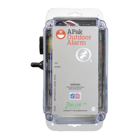
10-4013 pictured
ALARM INSTALLATION INSTRUCTIONS
*LED, alarm, and Z Control®connectivity have different behaviors in battery-only mode. See chart on page 7.
Wi-Fi® is a registered trademark of Wi-Fi Alliance®.

© Copyright 2018 Zoeller®Co. All rights reserved.
2
MECHANICAL FLOAT SWITCH
(10-4014)
1) Place cord into clamp and secure to discharge pipe as shown in clamp detail (see Figure F). NOTE: Do not install the cord under the hose clamp.
2) Tighten the hose clamp with a screwdriver. NOTE: Do not over tighten; over-tightening may cause damage to the plastic clamp.
3) Makesuretheoatcableisnotallowedtotouchtheexcesshoseclampbandduringoperation.
4) Theoatswitchmustbesuspended7”(17.8cm)belowdesiredactivationlevel(seeFigureG).
5) Becertainthatinstallationofoatallowsforunobstructedrangeofmotion.
LIFT PUMP
Suspend control switch above pump turn on level. If a pump failure causes high-level condition, the APak®Alarm System will activate (see Figure A).
HOLDING TANK
Suspendcontrolswitchintotank7”(17.8cm)belowdesiredalarmlevel.APak®AlarmSystemwillactivateifoatascendstoalarmlevel(seeFigureG).
NOTE: Alarm system 10-4014 is recommended for sewage applications. If a 10-4013 is used in a sewage
application,theoatshouldbeinspectedandcleanedasnecessaryafteranyhighwaterincident.
VERTICAL REED SENSOR
(10-4013)
DO NOT install sensor in direct line of incoming liquid.
1) Fasten sensor to right-angle mounting bracket by unthreading plastic nut. Re-tighten plastic nut after inserting sensor stem in bracket (see Figure C).
2) Locate sensor at desired activation level and secure mounting bracket to the discharge pipe as shown (see Figures C, D, and E) using supplied hose clamp.
NOTE: DO NOT install cord under hose clamp.
3) Secure sensor cord to discharge pipe. Be sure not to leave any loose cord that could rub against and obstruct other devices in basin assembly.
NOTE:Createacablestrainreliefwhensecuringthecontrolswitchcordbyfasteninga2”(50mm)loopofthecordtothepipewithacabletieortape.Besure
sensoroatmovesupanddownwithoutinterference.
Figure C Figure D
CONTROL SWITCH INSTALLATION
Figure E
CLAMP & BRACKET DETAIL
ALARM
LEVEL
CONTROL SWITCH
NORMALLY OPEN
SK1301E SK1301D SK1301E
Manufacturer warrants, to the purchaser and subsequent owner during
the warranty period, every new product to be free from defects in material
and workmanship under normal use and service, when properly used and
maintained,fora periodof5years fromdateofpurchase bytheenduser. Parts
that fail within the warranty period, that inspections determine to be defective
in material or workmanship, will be repaired, replaced or remanufactured at
Manufacturer’s option, provided however, that by so doing we will not be
obligated to replace an entire assembly, the entire mechanism or the complete
unit. No allowance will be made for shipping charges, damages, labor or
other charges that may occur due to product failure, repair or replacement.
This warranty does not apply to and there shall be no warranty for any
material or product that has been disassembled without prior approval of
Manufacturer,subjectedtomisuse,misapplication,neglect,alteration,accident
or uncontrollable act of nature; that has not been installed, operated or
maintainedinaccordancewithManufacturer’sinstallationinstructions;thathas
beenexposedtooutsidesubstancesincludingbutnotlimitedtothefollowing:
sand, gravel, cement, mud, tar, hydrocarbons, hydrocarbon derivatives (oil,
gasoline,solvents,etc.),orotherabrasiveorcorrosivesubstances,washtowels
or feminine sanitary products, etc. in all pumping applications. The warranty
setoutintheparagraphaboveisinlieuofallotherwarrantiesexpressedor
implied;and wedonot authorizeany representativeorother persontoassume
for us any other liability in connection with our products.
Contact Manufacturer at, 3649 Cane Run Road, Louisville, Kentucky 40211,
Attention: Customer Support Department to obtain any needed repair or
replacement of part(s) or additional information pertaining to our warranty.
MANUFACTURER EXPRESSLY DISCLAIMS LIABILITYFOR SPECIAL,
CONSEQUENTIAL OR INCIDENTAL DAMAGES OR BREACH
OF EXPRESSED OR IMPLIED WARRANTY; AND ANY IMPLIED
WARRANTY OF FITNESS FOR A PARTICULAR PURPOSE AND OF
MERCHANTABILITY SHALL BE LIMITED TO THE DURATION OF THE
EXPRESSED WARRANTY.
Some states do not allow limitations on the duration of an implied warranty,
so the above limitation may not apply to you. Some states do not allow the
exclusionorlimitationofincidentalorconsequentialdamages,sotheabove
limitationorexclusionmaynotapplytoyou.
Thiswarrantygivesyouspeciclegalrightsandyoumayalsohaveother
rights which vary from state to state.
LIMITED WARRANTY

© Copyright 2018 Zoeller®Co. All rights reserved.
3
Connect the two conductors from the control or mechanical switch to either pair of input terminals on the bottom of the alarm unit (see Figure B). The control
switch operates on low voltage to reduce shock hazards. The second input may be used to connect a second switch or dry contacts from another device.
OPERATION AND TESTING
Checkandtestyourinstallationbyliftingtheoatmanually(seeFigureEorG).Thealarmunitwillindicateanalarmconditionbybeepingandlightingared
LEDabove“Input1”.Thealarmmaybesilencedfor24hours*bybrieypressingtheSilencebutton.Oncesilenced,theLEDchangestoaashingstateandthe
audible horn will not sound. Once the high water condition is remedied, the alarm should be reset by holding the Silence button for 2 seconds. Zoeller Company
cannotberesponsiblefordamagescausedbyfaultyornegligentinstallationofthisdevice.Werespectfullysuggestyouengagetheservicesofaqualied,
licensed electrician or service person. Hold the Silence button for more than 4 seconds to test once per week to verify proper operation.
CONTROL/MECHANICAL SWITCH WIRING
7” (17.8 cm)
TETHER LENGTH
FOR ALARM FLOAT
SK1301F
Figure F
CLAMP DETAIL
SK1301G
Figure G
7"
ALARM
LEVEL
CLAMP
DETAIL
For units without internet connectivity, see the standard APak®10-4011, 10-4012.
Models 10-4013-A 10-4014-A
Item Description Qty
3/16
thru
Current
3/16
thru
Current
1 Clamp, #36 worm-SS 1 001766 001766
2 Supply, power (service part) 1 154018 154018
3 Switch, vertical reed (service part) 1 154033 N/A
4Switch,mechanicaloat 1 N/A 10-2060
SK3113
During a power outage, the APak®will beep every 30 seconds until the power is restored. If a high water alarm occurs during power outage with batteries
installed, the alarm will sound every 5 seconds.
*24 hours is the default setting. This and other settings may be changed from Z Control®Cloud.

© Copyright 2018 Zoeller®Co. All rights reserved.
4
CONNECTING THE APAK®TO Z CONTROL®
By connecting the APak®to the Z Control®Cloud using the built-in Wi-Fi®,theusercansetupfreealertmessagesviaemail,text,andmobileapp“push”
notications.Inaddition,theusercanverifytheAPak®’sreadiness,remotelysilencealarmsandresettheunit,conguresettings,andmodifyhownotications
are sent. Other visual information such as input status and battery level are available through the web and app interfaces.
Before you begin:
• Know what your Wi-Fi®routerisnamed(i.e.itsSSID)anditspassword.Doublecheckyouknowthecorrectpasswordandexactlyhowitisspelled,
including capitalization. This will prevent the most common troubleshooting issue.
• Verify your Wi-Fi®router is connected to the internet.
• Verify your phone, tablet, or computer has working Wi-Fi®, can connect to your Wi-Fi®router, and that you can be close to the APak®during the
installation process.
• Create a free account at zcontrolcloud.com.
• Locate the APak®’s Device ID on the top sticker.
Connection Steps:
1. Apply AC Power to the APak®(see note below for battery only installation**). The Z Control®LED will blink and then turn off, indicating the APak®is in
AP Mode* and is transmitting an SSID (see Figure H). If the LED is blinking and not in AP mode, either press the Silence button for 12 seconds and let
go OR hold the Silence button while applying AC power. The LED will now be off, indicating the APak®is in AP Mode.
This LED should be off when
APak®is in AP mode.
When user is connected to
APak®to set up Wi-Fi®, LED
will blink.
When APak®is connected to
router and Z Control®Cloud,
this LED will be solid.
AC power must be used
for AP mode to work
*AP Mode is when the APak®is broadcasting its
“name”,orSSID.TheSSIDisintheformatZCTL_
APAK_xxxxwhere“xxxx”istherst4digitsofyour
APak®’s Device ID. The APak®’s SSID will show up in
your phone/tablet/computer’s list of available Wi-Fi®,
and selecting it will give you direct connectivity to the
APak®. This is required in order to give the your APak®
the password credentials needed to connect to the
Wi-Fi®of your choice.
**Battery Only Mode. The APak®will not broadcast
an SSID when powered by batteries (DC) only. It
must have AC power to broadcast an SSID. Once
the APak®is connected to Wi-Fi®, AC power may be
removed if desired. Since the APak®has previously
seen AC power and it has been removed, the APak®
will now beep every 30 seconds indicating a power
outage. To remedy, remove battery power for a
moment, then reinsert batteries. The APak®will no
longer alarm for AC Power Out (unless AC Power
is again applied and then removed). The LEDs and
alarm will behave differently than when AC is present
in order to conserve battery power. In battery only
mode, the APak®will check into the Z Control®Cloud
far less often in order for the batteries to last for
approximately1year.
Figure H

© Copyright 2018 Zoeller®Co. All rights reserved.
5
2. Standing near the APak®, use your phone, tablet, or computer to look for the APak®’s SSID in your Wi-Fi®settings (see Figure I). It will look like
“ZCTL_APAK_xxxx”where“xxxx”istherst4digitsofyourAPak®’s Device ID. Select this, and 2 things will happen:
1. The Z Control®LEDwillashquickly.
2. A Z Control®setup screen will open after a few seconds.
Ifthesetupscreendoesnotappear,openabrowseronthesamedeviceandtype“zcong.zoeller.com”or“192.168.125.1”intheaddressbar.Ifthe
setup screen appears but is not used (cancelled or otherwise closed), the APak®will return to AP mode and the Z Control®LED will turn off until the
nextWi-Fi®setup attempt.
3. On the setup screen (see Figure J), press the “Wi-Fi®Scan”button,scrolldowntoseethelistofWi-Fi®signals found, and choose the Wi-Fi®you want
the APak®touseforinternetconnectivity.Enterthepasswordfortherouteryouchoseintheeldindicated.Ifthepasswordiscorrect,theAPak®will
connect to the router and start sending status updates to zcontrolcloud.com. You will see the Z Control®LED go from blinking to solid. This could take
up to a minute or so.
IftheLEDdoesnotturnsolid,thenthepasswordenteredisincorrect,therouter’ssecurityisinsufcient(seenotebelow**),orsomeothernetwork
restriction is in place (see your network administrator). The APak®will return to AP mode if the connection to router is not successful. If you need to
force the APak®into AP mode again, either press the Silence button for 12 seconds OR hold the Silence button while applying AC power. Either of
these methods will cause the APak®to re-enter AP mode and begin transmitting its SSID again.
Select the APak®’s SSID
Click Wi-Fi®Scan button
Available Wi-Fi®will be listed
here. Select the one you want.
**Note that the APak®willnotconnecttorouterswith“WEP”or“OPEN”security.
Figure I
Figure J

© Copyright 2018 Zoeller®Co. All rights reserved.
6
Congratulations! Your APak®isonline.Youcannowopentheproduct’scongurationbyclickingthe“View”buttontomodifytheAPak®’sdeviceandnotication
settings.
You can also install the Z Control®mobileapponyourmobiledevice(AndroidandiOSversionsavailable,search“ZControl”intheappstores).Thisappallows
for easy access to device information. Silence, Reset, and Test functionality is also included. The app is not currently designed for setting up Wi-Fi®, creating an
account,oraddingdevices.Thesestepscanonlybedonethroughthewebinterface(usingamobiledevicetoaccessthewebinterfaceisne).Settingupthe
APak®to use your Wi-Fi®is completed by connecting to the APak®’s internal Wi-Fi®(as discussed in the above Connection Steps).
4. Once the APak®’s Z Control®LEDissolid,logintoyouraccount(orcreateone)atzcontrolcloud.com(seeFigureK).ClicktheEditbuttonnexttoa
Location, and choose Add New Device. Follow the directions to add your APak®by either auto-detect or entering the Device I.D. When successful, an
APak®product tile will appear in your account.
The Apak®iscapableof“overtheair”rmwareupdates.It’spossiblethattheAPak®could perform an update immediately if one is available at the Z
Control®Cloud. If an update is taking place, the Z Control®LEDwillickerforupto1minutewhiletheupdateisdownloaded.TheZControl® LED will
be solid and all other LEDs will turn off while the update is being installed. After up to 1 minute, the APak®will restart and return to normal operation.
The APak®’s alert history on the Z Control®Cloudwillalsobeupdatedwiththermwareupgradeinformation,andnocationtoemailaccountswill
occur.
When you add the correct
Device ID, an APak®product tile
will appear in your account
Select Add New Device
Figure K

© Copyright 2018 Zoeller®Co. All rights reserved.
7
APAK®LED, BUTTON, ALARM, AND Z CONTROL®BEHAVIORS
*AP Mode is when the APak® is broadcasting its “name”, or SSID. The SSID is in the format ZCTL_APAK_xxxx where “xxxx” is the rst 4 digits of your APak®’s
Device ID. The APak’®s SSID will show up in your phone/tablet/computer’s list of available Wi-Fi®, and selecting it will give you direct connectivity to the APak®.
This is required in order to give your APak®the password credentials needed to connect to the Wi-Fi®of your choice.
AC and DC Mode AC Only Mode DC Only Mode
LED and Alarm
Behaviors
Power LED Power LED is on when AC and DC
power are present.
Power LED is on when AC power
is present.
Power LED off when only batteries
have been inserted, but will blink
when button pressed.
Input 1 or Input 2 In
Alarm
Input LED on solid.
Alarm triple beeps continuously.
Input LED on solid.
Alarm triple beeps continuously.
Input LED blinks and alarm double
beep every 5 seconds.
Low Battery Alarm Power LED blinks.
Alarm triple beeps every 5
seconds.
N/A Power LED blinks and alarm
beeps every 10 seconds.
Power Out Alarm All LEDs go out to conserve bat-
tery power.
Power LED blinks and alarm
double beeps every 30 seconds.
N/A N/A
Z Control®LED LED is solid when connected to
router and Z Control Cloud.
LED is off when APak®is in AP
mode.*
LED blinks when Wi-Fi®setup is in
process.
LED blinks faster if APak®is
attempting to reconnect to a
known router.
LED alternates blinking fast then
slow when APak is connected to
router but internet is lost.
LED is solid when connected to
router and Z Control®Cloud.
LED is off when APak®is in AP
mode.*
LED blinks when Wi-Fi®setup is in
process.
LED blinks faster if APak®is
attempting to reconnect to a
known router.
LED alternates blinking fast then
slow when APak®is connected to
router but internet is lost.
In order to conserve battery power,
Z Control®LED is dimly lit while
connected to the router and Z
Control®Cloud and off when the
Wi-Fi®module is in low power
mode. AC power is required for
Wi-Fi®setup (see directions). To
test connectivity, trigger an Input.
Silence Button Press/Release Silences Alarms. LED that is in
alarm stays on (or blinks) until
APak®is Reset.
Silences Alarms. LED that is in
alarm stays on (or blinks) until
APak®is Reset.
Silences alarm. LED still blinks
every 5 seconds until alarm is
Reset. In standby mode, a short
beep will occur to indicate APak®
is ready.
Hold 3 Seconds Resets any active alarms and
returns APak®to standby mode.
Resets any active alarms and
returns APak®to standby mode.
Resets any active alarms and
returns APak®to standby mode.
Hold 4 Seconds Initiates a LED and Alarm Test.
Willashanddoublebeep3times.
Initiates a LED and Alarm Test.
Willashanddoublebeep3times.
Initiates a LED and Alarm Test.
Willashanddoublebeep3times.
Hold While Applying AC
To APak®
APak®will enter AP mode*. For
APak®to revert to previous Wi-Fi®
settings, power cycle again.
APak®will enter AP mode*. For
APak to revert to previous Wi-Fi®
settings, power cycle again.
APak®will enter AP mode*. For
APak®to revert to previous Wi-Fi®
settings, power cycle again. See
"Battery Mode Only" note above.
Hold 12 Seconds Complete reset of APak®to factory
settings, including erasing Wi-Fi
settings®. APak®will enter AP
mode.*
Complete reset of APak®to factory
settings, including erasing Wi-Fi®
settings. APak®will enter AP
mode.*
Complete reset of APak®to factory
settings, including erasing Wi-Fi®
settings.
Communications
and Battery Life
Communication With
Z Control®Cloud
Communication is nearly
continuous.
Communication is nearly
continuous.
Limited to once per day to
conserve battery power.
Communication with
Z Control®Cloud Lost
Noticationsenttouserafter10
minutes of no communication.
Noticationsenttouserafter10
minutes of no communication.
Noticationsenttouserafter24
hours of no communication.
Alarm Condition
Present
Immediate communication to
Z Control®Cloud.
Immediate communication to
Z Control®Cloud.
Immediate communication to
Z Control®Cloud.
Auxiliary Output Triggered for Input 1, Input 2,
Power Out, and Low Battery
Alarms.
Triggered for Input 1 and Input 2
Alarms.
Does not function*
Battery Life 1-2 years with normal use. N/A Approximately1yearwithnormal
use.

© Copyright 2018 Zoeller®Co. All rights reserved.
8
MAILTO: P. O . BOX 16347 • Louisville, KY 40256-0347
SHIPTO: 3649 Cane Run Road • Louisville, KY 40211-1961
(502) 778-2731 • 1 (800) 928-PUMP • FAX (502) 774-3624 Visit our web site:
zoellerpumps.com
These are the original installation instructions.

9
© Copyright 2018 Zoeller®Co. Todos los derechos reservados.
Para uso en interiores solamente.
Deberán cumplirse todos los códigos de electricidad y seguridad además del Código Eléctrico Nacional y todos los códigos locales pertinentes.
No conecte dispositivos encendidos a la entrada.
ESPECIFICACIONES
Esta unidad de alarma monitorea el nivel de líquido en cámaras de bomba elevadora, contenedores para agua de bombas de sumidero, tanques de almacenamiento
y otras aplicaciones de agua no potable. Cuenta con una luz verde indicadora de alimentación, una luz roja de entrada, un timbre audible y botón de silencio/prueba.
Cuenta con un LED verde indicador de alimentación, LED rojas de entrada 1 y entrada 2, un timbre audible, contactos secos normalmente cerrados y un botón de
silencio/reinicio/prueba. La APak®se enchufa en un receptáculo de 120 V, 60 Hz. La energía de reserva de la batería se aplica con 2 baterías alcalinas estándar
AA, que no vienen incluidas y deben adquirirse por separado.
INSTALACIÓN DE LA UNIDAD DE ALARMA
1) Antes de instalar la alarma, retire los 4 tornillos de la tapa para acceder al compartimiento de las baterías (vea la Figura B) e instale 2 baterías AA, no incluidas.
2) Monte la unidad de alarma con los tornillos y anclajes.
3) Enchufe el conector de cilindro del transformador en la APak®.Fijeelcabledealimentacióndemodoquenoobstaculiceniintereraconotrosdispositivos.
4) NOTA: Se escuchará un pitido fuerte cuando se complete este paso.
Conecte el transformador al receptáculo estándar de 120 V CA 60 Hz.
NOTA: La alarma APak®debe conectarse a un circuito separado del circuito de la bomba.
LasinstalacionesqueutilizanalimentaciónybateríasdeCApuedenomitirlasiguienteexplicaciónygráco.Algunasinstalacionespuedenrequerirquelaalarma
APak®sea alimentada solo por baterías o solo por alimentación de CA. Para obtener un comportamiento adecuado de la alarma en este tipo de instalaciones,
consulte la siguiente tabla.
FM2943S
Figura A
SK3103
SILENCE
INPUT1
5VDC
NIVEL DE
ENCENDIDO (“ON”)
DE LA ALARMA
NIVEL DE
ENCENDIDO (“ON”)
DE LA BOMBA
NIVEL DE APAGADO
(“OFF”) DE LA BOMBA
CONTENEDOR
ZOELLER®
PARA AGUA DE FIBRA
DE VIDRIO O DE
POLIETILENO
102 mm (4 pulg.)
DE GRAVILLA
ALARMA
ZOELLER®
TRANSFORMADOR A LA FUENTE DE
ALIMENTACIÓN
NOTA: NO ENCHUFE EL SISTEMA
DE ALARMA APAK® EN EL MISMO
CIRCUITO QUE LA BOMBA
A LA FUENTE
DE ALIMENTACIÓN
UNICHECK
SENSOR
VERTICAL REED
DE ZOELLER®
ENTRADA 1 PARA EL
CONTROL DEL INTERRUPTOR
ENTRADA 2
CONTACTO SECO
RETIRE (4) TORNILLOS DE
LA TAPA PARA INSTALAR/
CAMBIAR LAS BATERÍAS
A LA FUENTE DE ALIMENTACIÓN
Figura B
SK3102
Opción de alimentación Comportamiento resultante de la alarma Haga esto
CA y baterías Alarmas de corte de energía y de batería baja. Inserte las baterías y conecte a la alimentación.
CA solamente Alarma de batería baja desactivada.
Sostenga el botón durante unos 5 segundos mientras enciende la alarma
hasta escuchar un solo pitido, a continuación suelte el botón. Este ajuste será
recordado por la alarma, incluso después de un corte de energía. Si ya no se
desea esta opción, simplemente ponga las baterías para eliminar este ajuste.
Solo baterías* Alarma de corte de energía desactivada. Inserte las baterías. La alarma no detectará la alimentación de CA si nunca la
ha tenido.
10-4011 ilustrado
La información presentada
adentro reeja condiciones al
tiempo de publicación. Consultar
la fábrica sobre discrepancias o
contradicciones.
DIRECCIÓN POSTAL: P.O. BOX 16347 • Louisville, KY 40256-0347 EEUU
DIRECCIÓN PARA ENVÍOS: 3649 Cane Run Road • Louisville, KY 40211-1961 EEUU
TEL: +1 (502) 778-2731 • FAX: +1 (502) 774-3624
Visite a nuestro sitio web:
zoellerpumps.com
Confiable. Probado. Resistente.™
Aviso al contratista instalador: Las instrucciones deberán permanecer con la instalación.
INSTRUCCIONES DE INSTALACIÓN DE LA ALARMA
* Los LED, alarmas y conectividad Z Control®tienen distintos comportamientos en el modo solo batería. Vea la tabla en la página 15.

10
© Copyright 2018 Zoeller®Co. Todos los derechos reservados.
INTERRUPTOR DE FLOTADOR MECÁNICO
(10-4014)
1) Coloque el cable en la abrazadera y fíjelo a la tubería de descarga como se muestra en el detalle de la abrazadera (vea la Figura F). NOTA: No instale el cable
debajo la abrazadera de la manguera.
2) Apriete la abrazadera de la manguera con un destornillador. NOTA: no apriete demasiado; apretar demasiado puede causar daños a la abrazadera de plástico.
3) Asegúresedequeelcabledelotadornotoqueelexcesodebandadelaabrazaderademangueraduranteelfuncionamiento.
4) Elinterruptordeotadordebeestarsuspendidoa17.8cm(7pulg.)pordebajodelniveldeactivacióndeseado.(vealaFiguraG).
5) Asegúresedequelainstalacióndelotadorpermitaunrangodemovimientosinobstrucciones.
BOMBA ELEVADORA
Suspenda el interruptor de control por encima del nivel de encendido de la bomba. Si una falla de la bomba provoca una condición de alto nivel, el sistema de
alarma APak®se activará (vea la Figura A).
TANQUE DE RETENCIÓN
Suspendaelinterruptordecontroleneltanquea17.8cm(7pulg.)pordebajodelniveldealarmadeseado.ElsistemadealarmaAPak®seactivarásielotador
asciendealniveldealarma(vealaFiguraG).
NOTA: Para aplicaciones de aguas negras se recomienda el sistema de alarma 10-4010. Si se usa un sistema 10-4013 en una aplicación
deaguasnegras,sedebecontrolarylimpiarelotadorsegúnseanecesariodespuésdecualquierincidentedealtoniveldeagua.
SENSOR REED VERTICAL
(10-4013)
!
ADVERTENCIA NO instale el sensor en línea directa del líquido entrante.
1) Fije el sensor al soporte de montaje en ángulo recto desenroscando la tuerca de plástico. Vuelva a apretar la tuerca de plástico después de insertar el vástago
del sensor en el soporte (vea la Figura C).
2) Coloqueelsensorenelniveldeactivacióndeseadoyjeelsoportedemontajealatuberíadedescargacomosemuestra(vealasFigurasC,DyE),utilizando
la abrazadera de manguera suministrada.
NOTA: NO instale el cable debajo de la abrazadera de la manguera.
3) Fije el cable del sensor a la tubería de descarga. Asegúrese de no dejar ningún cable suelto que pudiera rozar con y obstruir otros dispositivos en el conjunto
de contenedor para agua.
NOTA:Creeunpasacablesaljarelcabledelinterruptordecontroljandounbuclede5.1cm(2pulg.)decablealatuberíaconunabridaparacablesocinta
adhesiva.Asegúresedequeelotadordelsensorsemuevahaciaarribayhaciaabajosininterferencias.
Figura C Figura D
INSTALACIÓN DEL INTERRUPTOR DE CONTROL
Figura E
NIVEL DE
ALARMA
INTERRUPTOR
DE CONTROL
NORMALMENTE
ABIERTO
SK1301E SK1301D SK1301E
Mientras dure el período de garantía, el fabricante garantiza al comprador,
y al subsiguiente propietario, que los productos nuevos no tendrán defectos
de material ni mano de obra por el uso y el servicio normales, siempre
que se usen y se mantengan debidamente, durante cinco años a partir
de la fecha de compra del usuario nal. Las partes que fallen durante
el período de garantía, cuyas inspecciones determinen que presentan
defectos en materiales o mano de obra, serán reparadas, reemplazadas o
remanufacturadas a opción del Fabricante, con la condición sin embargo de
que por hacerlo no estemos en la obligación de reemplazar un ensamblaje
completo, el mecanismo entero o la unidad completa. No se dará concesión
alguna por costos de envío, daños, mano de obra u otros cargos que
pudieran surgir por falla, reparación o reemplazo del producto.
Esta garantía no aplica a y no se ofrecerá garantía alguna por ningún material
o producto que haya sido desarmado sin aprobación previa del Fabricante,
o que haya sido sometido a uso indebido, aplicación indebida, negligencia,
alteración, accidente o acto fortuito; que no haya sido instalado, usado o
mantenido según las instrucciones de instalación del Fabricante; que haya
sidoexpuestoasustanciasforáneasqueincluyenperonoselimitanalo
siguiente: arena, grava, cemento, lodo, alquitrán, hidrocarburos, derivados de
hidrocarburos (aceite, gasolina, solventes, etc.), u otras sustancias abrasivas
o corrosivas, toallas para lavar o productos sanitarios femeninos, etc. en todos
los usos de bombeo. La garantía presentada en el párrafo anterior deja sin
efectocualquierotragarantíaexpresaoimplícita;ynoautorizamosaningún
representante u otra persona para que asuma por nosotros ninguna otra
responsabilidad con respecto a nuestros productos.
Comuníquese con el Fabricante en 3649 Cane Run Road, Louisville, KY
40211 EE.UU., a la atencion del Customer Support Department, para
obtener cualquier reparación necesaria o reemplazo de partes o información
adicional sobre nuestra garantía.
EL FABRICANTE EXPRESAMENTE RECHAZA RESPONSABILIDAD
POR DAÑOS ESPECIALES, EMERGENTES O INCIDENTALES O
POR INCUMPLIMIENTO DE LA GARANTÍA EXPRESA O IMPLÍCITA;
Y CUALQUIER GARANTÍA IMPLÍCITA DE IDONEIDAD PARA UN
FIN PARTICULAR Y DE COMERCIALIZACIÓN SE LIMITARÁ A LA
DURACIÓN DE LA GARANTÍA EXPRESA.
Algunos estados no permiten limitaciones en la duración de una garantía
implícita, de forma que la limitación anterior podría no aplicar a usted.
Algunosestadosnopermitenlaexclusiónolimitacióndedañosincidentales
o emergentes, de forma que la limitación o exclusión anterior podría no
aplicar a usted.
Estagarantíaleotorgaaustedderechoslegalesespecícosypodríatener
otros derechos que varían de un estado a otro.
GARANTÍA LIMITADA
ABRAZADERA Y DETALLE
DEL SOPORTE

11
© Copyright 2018 Zoeller®Co. Todos los derechos reservados.
Conecte los dos conductores desde el interruptor de control o interruptor mecánico a cualquiera de los dos terminales de entrada en la parte inferior de la unidad
de alarma (vea la Figura B). El interruptor de control opera en baja tensión para reducir el riesgo de descargas. La segunda entrada puede usarse para conectar
un segundo interruptor o contactos secos a otro dispositivo.
FUNCIONAMIENTO Y PRUEBAS
Veriqueypruebelainstalaciónlevantandoelotadormanualmente(vealaFiguraEoG).Launidaddealarmaindicaráunacondicióndealarmaconpitidosy
encendiendounLEDrojoarribade“Input1”.Laalarmapuedesersilenciadadurante24horaspulsandobrevementeelbotónSilence.Unavezsilenciada,elLED
comienza a parpadear y la bocina audible no sonará. Una vez que la condición de nivel alto de agua se solucione, la alarma debe restablecerse manteniendo
pulsado el botón Silence durante al menos 3 segundos. Zoeller Company no puede responsabilizarse por daños causados por una instalación defectuosa o
negligentedeestedispositivo.Respetuosamentesugerimosquecontratelosserviciosdeunelectricistacerticadoopersonademantenimientocalicada.
MantengapulsadoelbotónSilencedurante3segundospararealizarlapruebaunavezporsemanaconelndevericarelfuncionamientocorrecto.
CABLEADO DEL INTERRUPTOR DE CONTROL/MECÁNICO
LONGITUD MÍNIMA
DE SUJECIÓN DE
17.8 CM (7 PULG.)
PARA EL
FLOTADOR DE
LA ALARMA
SK1301F
Figura F
DETALLE DE LA ABRAZADERA
SK1301G
Figura G
17.8 cm (7 pulg.)
NIVEL DE ALARMA
DETALLE DE
LA ABRAZADERA
Para unidades sinconexiónaInternet,consulteelAPak®estándar 10-4011, 10-4012.
Modelos 10-4013-A 10-4014-A
Artículo Descripción Cantidad
3/16
al
presente
3/16
al
presente
1 Abrazadera, #36 Worm-AI 1 001766 001766
2 Alimentación (parte de servicio) 1 154018 154018
3 Interruptor, reed vertical (parte de servicio) 1 154033 --
4Interruptor,otadormecánico 1 -- 10-2060
SK3113
Durante un apagón, el APak®emitirá un pitido cada 30 segundos hasta que vuelva la energía. Si se produce una alarma de alto nivel de agua durante un apagón
con las baterías instaladas, la alarma sonará cada 5 segundos.
*La conguración predeterminada es de 24 horas. Tanto esta como otras conguraciones se pueden cambiar desde la Z Control®Cloud.

12
© Copyright 2018 Zoeller®Co. Todos los derechos reservados.
CONECTAR EL APAK®AL Z CONTROL®
Al conectar APak®a la nube del Z Control®mediante el Wi-Fi®integrado,elusuariopuedecongurarmensajesdealertagratuitosporcorreoelectrónico,
mensajesdetextoynoticaciones“push”delaaplicaciónmóvil.Además,elusuariopuedevericarladisponibilidaddeAPak®, silenciar alarmas y restablecer
launidaddemaneraremota,ajustarlasconguracionesymodicarlaformadeenvíodelasnoticaciones.Otrainformaciónvisual,comoelestadodelas
entradas y el nivel de las baterías, está disponible por Internet y las interfaces de la aplicación.
Antes de comenzar:
• Conozca cuál es el nombre (el SSID) y la contraseña de su router Wi-Fi®. Cerciórese de saber cuál es la contraseña correcta y cómo se deletrea,
incluidas las mayúsculas y minúsculas. Esto evitará el problema más común en la solución de problemas.
• VeriquequesurouterWi-Fi®esté conectado a Internet.
• Veriquequesuteléfono,tabletaocomputadoratengaWi-Fi®en funcionamiento, pueda conectarse a su router Wi-Fi®y que pueda estar cerca de la
APak®durante el proceso de instalación.
• Cree una cuenta gratuita en zcontrolcloud.com.
• Localice el ID del dispositivo APak®en el adhesivo superior.
Pasos para la conexión:
1. Conecte la alimentación de CA a la APak®(ver nota a continuación para instalaciones solo con baterías^). El LED de Z Control®parpadeará y luego
se apagará, indicando que la APak®estáenmodoAP*yqueestátransmitiendoelSSID(verguraH).SielLEDparpadeaperonoestáenmodoAP,
presione el botón de Silencio durante 12 segundos y suéltelo O mantenga presionado el botón de Silencio mientras conecta la alimentación de CA. El
LED se apagará para indicar que la APak®está en modo AP.
Este LED debe estar
apagado cuando la APak®
esté en modo AP.
El LED parpadeará cuando
el usuario está conectado a
la APak®paracongurarel
Wi-Fi®.
EsteLEDsequedarájo
cuando la APak®esté
conectada al router y a la Z
Control®Cloud.
Se debe usar alimentación
de CA para que el modo
AP funcione.
*El modo AP es cuando la APak®transmite su
“nombre”oSSID.ElSSIDestáincluidoenelformato
ZCTL_APAK_xxxx,donde“xxxx”sonlosprimeros4
dígitos del ID de su dispositivo APak®. El SSID de la
APak®aparecerá en la lista de Wi-Fi®disponibles en
su teléfono/tableta/computadora y al seleccionarlo
le dará conectividad directa a la APak®. Esto es
necesario para que su APak®reciba las credenciales
necesarias de la contraseña para conectarse al Wi-Fi®
que elija.
^Modo solo batería. La APak®no transmitirá un SSID
si solo está alimentado por baterías (CC). Debe tener
alimentación de CA para transmitir un SSID. Una vez
la APak®esté conectada al Wi-Fi®, se puede quitar la
alimentación CA si se desea. Dado que la APak®ha
recibido previamente alimentación de CA y luego se
la ha desconectado, la APak®emitirá un pitido cada
30 segundos indicando la falta de energía. Para
solucionarlo, quite las baterías por un momento y
luego vuelva a colocarlas. La APak®ya no sonará por
la falta de alimentación CA (a menos que se vuelva a
aplicar y quitar energía de CA). Los LED y la alarma
tendrán comportamientos diferentes a cuando esté
conectada a la alimentación de CA para conservar
la energía de la batería. En el modo solo batería, la
APak®ingresará a la nube del Z Control®con mucha
menos frecuencia para que las baterías puedan durar
aproximadamente1año.
Figura H

13
© Copyright 2018 Zoeller®Co. Todos los derechos reservados.
2. Párese cerca de la APak®y use su teléfono, tableta o computadora para buscar el SSID de la APak®enlaconguracióndesuWi-Fi®(verguraI).
Aparecerácomo“ZCTL_APAK_xxxx”,donde“xxxx”sonlosprimeros4dígitosdelIDdesudispositivoAPak®. Selecciónelo y aparecerán 2 cosas:
1. El LED de Z Control®parpadeará rápidamente.
2.Luegodeunossegundos,seabrirálapantalladeconguracióndelZControl®.
Silapantalladeconguraciónnoaparece,abraunnavegadorenelmismodispositivoyescriba““zcong.zoeller.com””o“192.168.125.1”enlabarra
dedirecciones.Silapantalladeconguraciónapareceperonoesutilizada(sisecancelaosecierra),laAPak®volverá al modo AP y el LED del Z
Control®seapagaráhastaqueseintentelaconguraciónWi-Fi®de nuevo.
3. Enlapantalladeconguración(verguraJ),presioneelbotón“Wi-Fi®Scan”,deslícesehaciaabajoparaverlalistadeseñalesdeWi-Fi®disponibles
y elija el Wi-Fi®que quiere usar para que la APak®tengaconexiónaInternet.Ingreselacontraseñadelrouterqueeligióenelcampoindicado.Sila
contraseña es correcta, la APak®se conectará al router y comenzará a enviar actualizaciones de estado a zcontrolcloud.com. Verá que el LED del Z
Control®dejadeparpadearysequedajo.Estopuededemoraralrededordeunminuto.
SielLEDnoquedajo,entonceslacontraseñaingresadaesincorrecta,laseguridaddelrouteresinsuciente(verlanotaacontinuación***),oexiste
algún tipo de restricción de red (consultar con el administrador de red). La APak®volveráalmodoAPsilaconexiónalrouternotuvoéxito.Sinecesita
volver a poner la APak®en el modo AP, presione el botón de Silencio durante 12 segundos O mantenga presionado el botón de Silencio mientras
conecta la alimentación de CA. Cualquiera de estos métodos hará que la APak®vuelva a ponerse en modo AP y comience a transmitir su SSID
nuevamente.
Seleccione el SSID de la APak®
Haga clic en el botón “Wi-Fi®Scan”
Aquí aparecerán los Wi-Fi®disponibles.
Seleccioneelquepreere.
**TengaencuentaquelaAPak®noseconectaráalosrouters“ABIERTOS”Oconseguridad“WEP”.
Figura I
Figura J

14
© Copyright 2018 Zoeller®Co. Todos los derechos reservados.
¡Felicitaciones! Su APak®estáenlínea.Ahorapuedeabrirlaconguracióndelproductoalhacerclicenelbotón“View”(Ver)paramodicarlasconguraciones
deldispositivoynoticacionesdelaAPak®.
También puede instalar la aplicación móvil Z Control® en su dispositivo móvil (versiones disponibles eniOSyAndroid,busque“ZControl”en las tiendas de
aplicaciones). Esta aplicación facilita el acceso a la información del dispositivo. También se incluyen las funciones de Silencio, Restablecer y Prueba. La aplicación
noestádiseñadaactualmenteparacongurarelWi-Fi®, crear una cuenta o agregar dispositivos. Estos pasos solo se pueden llevar a cabo a través de una interfaz
web(sepuedeusarundispositivomóvilparaaccederalainterfazweb).LaconguracióndelaAPak®para usarla con su Wi-Fi®se realiza conectándose al Wi-Fi®
interno de la APak®(comoseindicóanteriormenteenPasosparalaconexión).
4. Una vez que el LED del Z Control®de la APak®sequedejo,ingreseasucuenta(ocreeuna)enzcontrolcloud.com(verFiguraK).Hagaclicenel
botónEdit(Editar)cercadeunaLocation(Ubicación)yseleccione“AddNewDevice”(Añadirnuevodispositivo).Sigalasinstruccionesparaagregar
su APak®,yaseaatravésdeladetecciónautomáticaoelingresodelIDdeldispositivo.Cuandolohayalogrado,apareceráensucuentalachadel
producto APak®.
La APak®tienecapacidadpararecibiractualizacionesdermwaredeformainalámbrica(“overtheair”).EsposiblequelaAPak®haga una actualización
de inmediato si hay alguna disponible en la Z Control®Cloud. Durante la actualización, el LED de Z Control®parpadeará por hasta 1 minuto mientras se
descarga la actualización. El LED del Z Control®sequedarájoytodoslosotrosLEDseapagarándurantelainstalacióndelaactualización.Luegode
hasta 1 minuto, la APak®se reiniciará y volverá a funcionar normalmente. El historial de alertas de la APak®en la Z Control® Cloud también se actualizará
conlainformacióndeactualizacióndelrmwareyseenviaránnoticacionesalascuentasdecorreoelectrónico.
Cuando agregue el ID del dispositivo
correcto,apareceráunachadel
producto APak®en su cuenta
Seleccione“AddNewDevice”
(Agregar dispositivo nuevo)
Figura K

15
© Copyright 2018 Zoeller®Co. Todos los derechos reservados.
COMPORTAMIENTO DE LOS LED APAK®, BOTÓN, ALARMA Y Z CONTROL®
*El modo AP es cuando la APak®transmite su “nombre” o SSID. El SSID está incluido en el formato ZCTL_APAK_xxxx, donde “xxxx” son los primeros 4 dígitos
del ID de su dispositivo APak®. El SSID de la APak®aparecerá en la lista de Wi-Fi®disponibles en su teléfono/tableta/computadora y al seleccionarlo le dará
conectividad directa a la APak®. Esto es necesario para que su APak®reciba las credenciales necesarias de la contraseña para conectarse al Wi-Fi®que elija.
Modos CA y CC Modo CA solamente Modo CC solamente
Comportamiento
de los LED y las
alarmas
LED de alimentación El LED de alimentación se enciende
cuando hay presencia de alimentación
CA y CC
El LED de alimentación se enciende
cuando hay presencia de alimentación
CA
El LED de alimentación se apagan
cuando solo se han colocado baterías,
pero parpadeará cuando se presione
el botón
Entrada 1 o entrada 2 en
la alarma
LEDdeentradaencendidojo.
La alarma hace tres pitidos
continuamente.
LEDdeentradaencendidojo.
La alarma hace tres pitidos
continuamente.
El LED de entrada parpadea y la
alarma hace dos pitidos cada 5
segundos
Alarma de batería baja. El LED de alimentación parpadea.
La alarma hace tres pitidos cada 5
segundos.
--
El LED de alimentación parpadea y la
alarma pita cada 10 segundos
Alarma de corte de energía Todos los LED se apagan para conser-
var batería.
El LED de alimentación parpadea y
la alarma hace dos pitidos cada 30
segundos.
-- --
LED de Z Control®ElLEDestájocuandoestá
conectado al router y a la nube del Z
Control®.
El LED está apagado cuando APak®
está en modo AP.*
El LED parpadea cuando la
conguracióndelWi-Fi®está en
proceso.
El LED parpadea más rápido si la
APak®está intentando volver a
conectarse a un router conocido.
El LED alterna entre parpadeo rápido y
lento cuando la APak®está conectada
aunrouterperosepierdelaconexión
a Internet.
ElLEDestájocuandoestá
conectado al router y a la nube del Z
Control®.
El LED está apagado cuando APak®
está en modo AP.*
El LED parpadea cuando la
conguracióndelWi-Fi®está en
proceso.
El LED parpadea más rápido si la
APak®está intentando volver a
conectarse a un router conocido.
El LED alterna entre parpadeo rápido y
lento cuando la APak®está conectada
aunrouterperosepierdelaconexión
a Internet.
Para conservar la energía de la
batería, el LED de Z Control®es
tenue cuando está conectado al
router y a la nube del Z Control®y
está apagado cuando el módulo
Wi-Fi®está en modo de energía
baja. Se requiere alimentación de
CAparalaconguracióndeWi-Fi®
(ver instrucciones). Para probar la
conectividad, active una Entrada
Botón de silencio Presionar/Soltar Silencia las alarmas. El LED de la
alarma se queda encendido (o parpa-
dea) hasta que se reinicie la APak®.
Silencia las alarmas. El LED de la
alarma se queda encendido (o parpa-
dea) hasta que se reinicie la APak®.
Silencia la alarma. El LED parpadea
cada 5 segundos hasta que se reinicie
la alarma. En modo de espera, hará un
pitido corto para indicar que la APak®
está lista.
Presionar por
2 segundos
Reinicia cualquier alarma activa y
regresa la APak®al modo de espera.
Reinicia cualquier alarma activa y
regresa la APak®al modo de espera.
Reinicia cualquier alarma activa y
regresa la APak®al modo de espera.
Presionar por
4 segundos
Inicia una prueba de LED y alarma.
Parpadeará y hará pitidos dobles 3
veces.
Inicia una prueba de LED y alarma.
Parpadeará y hará pitidos dobles 3
veces.
Inicia una prueba de LED y alarma.
Parpadeará y hará pitidos dobles 3
veces.
Mantener presionado al
conectar la APak®a la
alimentación CA
La APak®entrará al modo AP*. Para
que la APak®regrese a los ajustes de
Wi-Fi®anteriores, apague y vuelva a
encender.
La APak®entrará al modo AP*. Para
que la APak®regrese a los ajustes de
Wi-Fi®anteriores, apague y vuelva a
encender.
La APak®entrará al modo AP*. Para
que la APak®regrese a los ajustes de
Wi-Fi®anteriores, apague y vuelva a
encender. Ver arriba la nota sobre
“Modobateríasolamente”.
Mantener presionado 12
segundos
Restablece los ajustes de fábrica
de la APak®, elimina también las
conguracionesdeWi-Fi®. La APak®
entrará al modo AP*.
Restablece los ajustes de fábrica
de la APak®, elimina también las
conguracionesdeWi-Fi®. La APak®
entrará al modo AP*.
Restablece los ajustes de fábrica de la
APak®,eliminatambiénlascongura-
ciones de Wi-Fi®.
Comunicaciones
y duración de la
batería
Comunicación con la
Z Control®Cloud
La comunicación es casi continua. La comunicación es casi continua. Se limita a una vez por día para
conservar la carga de la batería
Pérdida de la
comunicación con la
Z Control®Cloud
Después de 10 minutos sin
comunicación, se envía una
noticaciónalusuario.
Después de 10 minutos sin
comunicación, se envía una
noticaciónalusuario.
Después de 24 horas sin
comunicación, se envía una
noticaciónalusuario
Condición de la alarma
presente
Comunicación inmediata a la Z
Control®Cloud
Comunicación inmediata a la Z
Control®Cloud
Comunicación inmediata a la Z
Control®Cloud
Salida auxiliar Se activa por alarmas de entrada 1,
entrada 2, corte de energía y batería
baja
Se activa por alarmas de entrada 1 y
entrada 2
No funciona*
Vida útil de la batería De 1 a 2 años con uso normal -- Aproximadamente1añoconuso
normal

16
Visite a nuestro sitio web:
zoellerpumps.com
CORREO A: P.O. BOX 16347 • Louisville, KY 40256-0347 EEUU
ENVÍOS A: 3649 Cane Run Road • Louisville, KY 40211-1961 EEUU
TEL: +1 (502) 778-2731 • FAX: +1 (502) 774-3624
Confiable. Probado. Resistente.™
Esta es una traducción de las instrucciones de instalación originales.
© Copyright 2018 Zoeller®Co. Todos los derechos reservados.

17
© Copyright 2018 Zoeller®Co. Tous droits réservés.
Usage intérieur uniquement.
Tous les codes de l’électricité et de sécurité ainsi que le code national de l’électricité et tous les codes et règlements locaux applicables doivent être
respectés.
Ne pas brancher les diapositives à l’entrée.
SPÉCIFICATIONS
Cettealarmesurveillelesniveauxduliquidedansleschambresdepompe,lescuvesdepompedepuisard,lesréservoirsderetenueetautresapplicationsd’eau
non potable. Elle dispose d’un voyant DEL vert « En marche », de voyants d’entrée rouges 1 et 2, d’une sonnerie, des contacts secs normalement fermés et d’un
bouton Silence / Réinitialisation / Test. L’alarme APak®sebranchedansunechede120Vet60Hz.L’alimentationdelabatteriedesecourssefaitpardeuxpiles
alcalines standard AA, qui ne sont pas fournies et doivent être achetées séparément.
INSTALLATION DE L’ALARME
1) Avantd’installerl’alarme,retirezles4visducouvercleand’accéderaucompartimentdespiles(voirFigureB)etinstallezlesdeuxpilesAA,nonfournies.
2) Montez l’alarme avec les vis et les boulons.
3) Branchez le connecteur cylindrique du transformateur dans l’alarme APak®.Attachezlecordond’alimentationanqu’iln’interfèrepasavecd’autresappareils.
4) REMARQUE:Unsignalsonoreindiquelandecetteétape.
Branchezletransformateurdansunechestandard120Vc.a.et60Hz.
REMARQUE : L’alarme APak®doit être connectée à un circuit séparé du circuit de la pompe.
Pour certaines installations, l’alarme APak®doitêtrealimentéeuniquementpardespilesouunealimentationparcourantalternatif.Anquel’alarmefonctionne
normalement dans de telles installations, suivez le tableau suivant.
FM2931F
Figure A
SK3103
SILENCE
INPUT1
5VDC
CUVE
ZOELLER® EN
FIBRE DE VERRE
OU POLYÉTHYLÈNE
NIVEAU
« MARCHE »
DE L’ALARME
NIVEAU
« MARCHE »
DE LA POMPE
NIVEAU
« ARRÊT »
DE LA POMPE
102 mm (4 po)
DE GRAVIER
ALARME
ZOELLER®
TRANSFORMATEUR VERS
SOURCE DE COURANT
REMARQUE : NE PAS BRANCHER LE
SYSTÈME D’ALARME APAK® SUR LE
MÊME CIRCUIT QUE LA POMPE
VERS LA SOURCE
DE COURANT
UNICHECK
CAPTEUR
VERTICAL REED
ZOELLER®
1 ENTREE POUR
CONTROLER L'INTERRUPTEUR
ENTREE 2
CONTACT SEC
RETIREZ LES (4) VIS DU
COUVERCLE AFIN D’INSTALLER
OU DE REMPLACER LES PILES
VERS LA SOURCE DE COURANT
Figure B
SK3102
Choix d’alimentation Comportement de l’alarme correspondant À faire
Courant alternatif et piles Alarmes de panne d’alimentation et de piles faibles. Insérer les piles et se connecter à l’alimentation.
Courant alternatif
uniquement Alarme de batterie faible désactivée.
Tenir le bouton enfoncé pendant que l’alarme est sous tension pour une durée
d’environ cinq (5 secondes) jusqu’à ce qu’un bip simple se fait entendre et
puisrelâcherle bouton. Ceréglageseraretenu parl’alarmemêmeaprès
qu’une panne de courant s’est produite. Si ce réglage n’est plus souhaité,
simplement ajouter des piles supprimera le réglage.
Piles uniquement* Alarme de panne d'alimentation désactivée. Insérez les piles. L’alarme ne détectera pas le courant alternatif s’il n’est pas
appliqué.
10-4011 illustré
Avis à l'installateur : Les instructions doivent rester avec l'installation.
ADRESSE POSTALE : P.O. BOX 16437 • Louisville, KY 40256-0347 USA
ADRESSE PHYSIQUE : 3649 Cane Run Road • Louisville, KY 40211-1961 USA
TÉL : +1 (502) 778-2731 • FAX : +1 (502) 774-3624
Visitez notre site internet :
zoellerpumps.com
Les renseignements présentés dans ce
document représentent les conditions
au moment de la publication. Consulter
l’usine en cas de désaccord et de manque
de cohérence.
Fiable. Irréprochable. Durable.™
INSTRUCTIONS D’INSTALLATION DE L’ALARME
*Les DEL, alarme et connectivité Z Control® se comportent différemment en mode d’alimentation par piles. Se référer au tableau de la page 23.

18
© Copyright 2018 Zoeller®Co. Tous droits réservés.
INTERRUPTEUR MÉCANIQUE À FLOTTEUR
(10-4014)
1) Placezlecordondanslecollieretxez-leàlaconduited’évacuationcommeillustrésurledétailducollier(voirFigureF).REMARQUE : Ne pas installer le
cordon sous le collier.
2) Serrez le collier à l’aide d’un tournevis. REMARQUE : Faites attention de ne pas trop serrer car le collier en plastique risque d’être endommagé.
3) Assurez-vousquelecâbleduotteurnetouchepasl’extrémitéducollierdurantlefonctionnement.
4) L’interrupteuràotteurdoitêtresuspenduà17,8cm(7po)au-dessusduniveaud’activationsouhaité.(voirFigureG)
5) S’assurerqueleotteuraétéinstallésansobstruersonmouvement.
POMPE DE LEVAGE
Suspendezl’interrupteurdecommandeau-dessusduniveaumarchedelapompe.Siladéfaillancedelapompeengendreuneconditiondeniveauélevé,lesystème
d’alarme APak®sera activé (voir Figure A).
RÉSERVOIR DE RETENUE
Suspendezl’interrupteurdecommandedansleréservoir17,8cm(7po)au-dessusduniveausouhaitédel’alarme.Lesystèmed’alarmeAPak®s’activera si le
otteurmonteauniveaudel’alarme(voirFigureG).
REMARQUE :Unsystèmed’alarme10-4014estrecommandépourlesapplicationsd’eauxusées.Siunsystème10-4013estutilisé
dansuneapplicationd’eauxusées,leotteurdoitêtrevériéetnettoyésinécessaireaprèsunincidentdeniveaud’eauélevé.
CAPTEUR VERTICAL REED
(10-4013)
AVERTISSEMENT
NE PAS installer le capteur en ligne directe avec un liquide entrant.
1) Fixezlecapteurausupportdexationàangledroitendévissantl’écrouenplastique.Resserrezl’écrouenplastiqueaprèsavoirinsérélatigeducapteurdans
le support (voir Figure C).
2) Placezlecapteurauniveaud’activationsouhaitéetxezlesupportdemontageàlaconduited’évacuationcommeillustré(voirlesFiguresC,DetE)àl’aidedu
collier de serrage fourni.
REMARQUE :NE PAS installer le cordon sous le collier du tuyau.
3) Fixezlecordonducapteuràlaconduited’évacuation.Assurez-vousqu’aucuncordondesserrénefrottecontreoun’obstrued’autresdispositifsdel’ensemble
de la cuve.
REMARQUE :Créezunréducteurdetensionenattachantlecordondel’interrupteurdecommandeenxantunebouclede5cm(2po)decordonsurletuyau,avec
uneattachedecâbleouduruban.Assurez-vousqueleotteurducapteursedéplaceverslehautetverslebassansinterférence.
Figure C Figure D
INSTALLATION DE L’INTERRUPTEUR À COMMANDE
Figure E
NIVEAU
D’ALARME
INTERRUPTEUR
À COMMANDE
NORMALEMENT
OUVERT
SK1301E SK1301D SK1301E
Le fabricant garantit à l’acheteur et au propriétaire ultérieur pendant la période
de garantie, tout produit neuf contre tout vice de matériel et de main-d’œuvre,
en utilisation normale et quand utilisé et entretenu correctement, pendant une
périodedecinqansàcompterdeladatedel’achatparl’utilisateurnal.Les
pièces devenant défectueuses pendant la période de garantie, et que des
inspections prouvent contenir des vices de fabrication ou de main-d’œuvre,
serontréparées,remplacéesourénovéesauchoixduFabricant,àcondition
qu’en faisant cela nous ne soyons pas obligés de remplacer l’ensemble, le
mécanisme complet ou l’appareil complet. Aucune provision n’est faite pour
lesfraisd’expédition,lesdégâts,lamain-d’œuvrenid’autresfraiscauséspar
la défaillance, la réparation ou le remplacement du produit.
Cette garantie ne s’applique pas et ne couvre aucun matériel ou produit qui
a été démonté sans l’autorisation préalable du Fabricant, soumis à un usage
abusif,desapplicationsincorrectes,delanégligence,desmodications,des
accidents ou un cas de force majeure ; qui n’a pas été installé, utilisé ou en-
tretenuselonlesinstructionsd’installationduFabricant;quiaétéexposé,y
compris, mais non de façon limitative, à du sable, des gravillons, du ciment,
de la boue, du goudron, des hydrocarbures ou des dérivés d’hydrocarbures
(huile, essence, solvants, etc.) ou à d’autres produits abrasifs ou corrosifs,
serviettesouproduitsd’hygièneféminineetc.,danstouteslesapplications
de pompage. La garantie mentionnée ci-dessus remplace toutes les autres
garantiesexpressesouimplicitesetnousn’autorisonsaucunreprésentantou
autre personne à accepter la responsabilité en notre nom pour nos produits.
Prendre contact avec le Fabricant, 3649 Cane Run Road, Louisville, KY
40211 USA, à l’attention du Customer Support Department, pour obtenir des
réparations, des pièces de remplacement ou des renseignements supplé-
mentaires concernant la garantie.
LE FABRICANT REFUSE EXPRESSÉMENT TOUTE RESPONSABILITÉ
POUR LES DÉGÂTS SPÉCIAUX, INDIRECTS OU SECONDAIRES OU
POUR LES RUPTURES DE GARANTIE EXPRESSES OU IMPLICITES; ET
TOUTE GARANTIE IMPLICITE D’APPLICABILITÉ À UNE UTILISATION
SPÉCIFIQUE OU DE COMMERCIALITÉ EST LIMITÉE À LA DURÉE DE LA
GARANTIE EXPRESSE.
Certaines provinces ne permettent pas les limitations de la durée de la garan-
tie implicite et il est possible que cette limitation ne s’applique pas. Certaines
provincesnepermettent pas l’exclusion ou la limitation des dégâts secon-
dairesouindirects,etilestpossiblequecettelimitationouexclusionnes’ap-
plique pas.
Cettegarantievousdonnedesdroitsspéciquesreconnusparlaloietvous
pouvez également avoir d’autres droits qui varient d’une province à l’autre.
GARANTIE LIMITÉE
COLLIER ET DÉTAIL DE BRIDE

19
© Copyright 2018 Zoeller®Co. Tous droits réservés.
Connecterlesdeuxconducteursdel’interrupteurdecommandeoumécaniqueàl’unedespairesdebornesenbasdel’unitédel’alarme(voirgureB).
L’interrupteurdecommandefonctionnesurtensionbasseanderéduirelesrisquesdechocélectrique.L’entrée2peutservirpourrelierundeuxièmeinterrupteur
ou contacts secs à un autre dispositif.
FONCTIONNEMENT ET TEST
Vériezettestezvotreinstallationenlevantmanuellementleotteur(voirgureEouG).L’unitéd’alarmeindiquerauneconditiond’alarmeenémettantunbip
etenallumantuneDELrougeau-dessusde«Input1».L’alarmepeutêtremiseensilencedurant24heuresenappuyantbrièvementsurlebouton«Silence».
Unefoisensilence,laDELchangeetclignotealorsquelasirèneneretentiraplus.Unefoislaconditiond’eauélevéerésolue,l’alarmedevraêtreréinitialisée
en maintenant le bouton «Silence» pendant au moins 3 secondes. Zoeller Company ne peut être tenu responsable de dommages causés par une installation
défaillanteoumalréaliséedecedispositif.Nousvoussuggéronsrespectueusementd’utiliserlesservicesd’unélectricienprofessionneletqualié.Unefoispar
semaine,maintenezlebouton«Silence»pendant3secondesandetesterlebonfonctionnementdel’alarme.
CÂBLAGE DE L’INTERRUPTEUR DE COMMANDE/MÉCANIQUE
ATTACHE DE
17,8 CM (7 PO)
POUR FLOTTEUR
D’ALARME
SK1301F
Figure F
DÉTAIL DU COLLIER
SK1301G
Figure G
17,8 cm (7 po)
NIVEAU
D’ALARME
DÉTAIL DU
COLLIER
Pour les dispositifs sansconnexionInternet,voirl’APak®standard 10-4011, 10-4012.
Modèles 10-4013-A 10-4014-A
Réf. Description Quant.
3/16
à
courant
3/16
à
courant
1 Collier, #36 Worm-AI 1 001766 001766
2Alimentation(pièce) 1 154018 154018
3Interrupteur,verticalreed(pièce) 1 154033 --
4Interrupteur,otteurmécanique 1 -- 10-2060
SK3113
Pendant une panne de courant, l’APak®émet un bruit toutes les 30 secondes jusqu’à ce que le courant soit rétabli. Si une alarme de niveau d’eau élevé se
produit pendant une panne de courant et lorsque des piles sont présentes, l’alarme retentira toutes les 5 secondes.
*« 24 heures » est le réglage par défaut. Ce paramétrage et d’autres peuvent être modiés à partir du Z Control®Cloud.

20
© Copyright 2018 Zoeller®Co. Tous droits réservés.
RACCORDEMENT DE L’ALARME APAK®AU Z CONTROL®
En raccordant l’APak®au Z Control®Cloud à l’aide du Wi-Fi®intégré,l’utilisateurpeutparamétrerdesmessagesgratuitsd’alerteparcourriel,messagetexteet
noticationssurletéléphonemobile.Deplus,l’utilisateurpeutvérierl’étatdefonctionnementdel’APak®, arrêter à distance l’avertisseur sonore de l’alarme et
réinitialiserl’unité,congurerlesdonnéesetmodierlemoyend’envoidesnotications.D’autresrenseignementsvisuelstelsquel’étatdesdonnéesetleniveau
de la batterie sont disponibles en ligne et par le biais des interfaces des applications.
Avant de commencer :
• Vous devez connaître le nom de votre routeur Wi-Fi®(c.-à-d.sonSSID)etsonmotdepasse.Vérierl’exactitudedumotdepasse,l’orthographeetles
majuscules.Vouséviterezainsiunproblèmetrèshabituel.
• VériezquevotrerouteurWi-Fi®est connecté à Internet.
• Vériezquevotretéléphone,tabletteouordinateurdisposeduWi-Fi®,peutseconnecteràvotrerouteurWi-Fi®etquevouspouvezêtreprèsde
l’APak®pendant le processus d’installation.
• Créez un compte gratuit sur zcontrolcloud.com.
• Voustrouverezl’identicationdel’alarmeAPak®sur l’autocollant supérieur.
Étapes de connexion :
1. Appliquerunealimentationc.a.ausystèmeAPak®(voir la note sur l’installation par piles uniquement). Le voyant DEL du Z Control®clignote puis
s’éteint pour indiquer que l’alarme APak®estenmodeAP*ettransmetunSSID(voirgureH).SilevoyantLEDclignoteetn’estpasenmodeAP,
appuyez soit sur le bouton Silence pendant 12 secondes puis relâchez OU maintenez le bouton Silence tout en appuyant sur l’alimentation c.a. Le
voyant DEL s’éteint pour indiquer que l’alarme APak®est en mode AP.
Ce voyant DEL doit être éteint
lorsque l’alarme APak®est en
mode AP.
Lorsque l’utilisateur est con-
necté à l’alarme APak®pour
paramétrerlaconnexionWi-Fi®,
la DEL clignote.
Lorsque l’alarme APak®est
connectée au routeur et au Z
Control®Cloud, ce voyant reste
allumé.
L’alimentation c.a. doit être
utilisée pour fonctionner en
mode AP
*LemodeAPsigniequel’alarmeAPak®diffusera
son « nom » ou SSID. Le SSID est au format
ZCTL_APAK_xxxx,«xxxx»étantlesquatrepremiers
chiffresdel’identiantdel’alarmeAPak®. Le SSID
de l’alarme APak®s’afcherasurlalistedesWi-Fi®
disponibles de votre téléphone / tablette / ordinateur, et
en le sélectionnant, vous serez directement connecté
à l’alarme APak®.Cetteconnexionestnécessairepour
transmettre le mot de passe de votre APak®pour se
connecter au Wi-Fi®devotrechoix.
Mode pile uniquement. L’APak®ne diffusera pas le
SSID lorsqu’elle est alimentée uniquement par les
piles (c.c.). Elle doit disposer d’une alimentation c.a.
pour diffuser le SSID. Une fois l’APak®connecté au
Wi-Fi®, l’alimentation c.a. peut être retirée si souhaité.
Étant donné que l’alarme APak®a été précédemment
alimentée en c.c. et que cette alimentation a été
retirée, l’alarme APak®émet un bip sonore toutes les
30 secondes pour indiquer une panne d’alimentation.
Pour y remédier, retirez les piles pour couper
l’alimentation par pile pendant un moment, puis
réinsérez-les. L’alarme APak®ne se déclenchera
plus pour les pannes d’alimentation c.a. (sauf si
l’alimentation c.a. est appliquée puis retirée). Les
voyants DEL et l’alarme se comporteront différemment
enlaprésencedel’alimentationc.a.andeconserver
l’alimentation par pile. En mode pile uniquement,
l’APak®vérieraleZControl®Cloud bien moins
souventandepréserverlespilesetpourlesfaire
durer au moins pendant un an.
Figure H
This manual suits for next models
3
Table of contents
Languages:
Other Zoeller Security System manuals
Popular Security System manuals by other brands

Paradox
Paradox ESPRIT 728 ULT Reference & installation manual

Abus
Abus CITADEL Alarm Set Micral Fitting and operating instructions

HIK VISION
HIK VISION DS-PRI120 user manual

Smart Witness
Smart Witness CP2 Series quick start guide

Camsat
Camsat ICAM-Mobile HD quick start

UNIONCOMMUNITY
UNIONCOMMUNITY UBio-X Iris user guide