Zoeller QWIK JON ULTIMA 202 User manual

© Copyright 2017 Zoeller®Co. All rights reserved.
QWIK JON®ULTIMA 202 SYSTEMS
INSTALLATION INSTRUCTIONS
1. To reduce the risk of electrical shock, a properly grounded receptacle or
control box of grounding type must be installed and protected by a ground
fault circuit interrupter (GFCI) in accordance with the National Electrical
Code and applicable local codes. Never remove ground pin from plug.
2. Make certain that the ground fault interrupter protected receptacle is within
reach of the pump’s power supply cord. DO NOT USE AN EXTENSION
CORD. Extension cords that are too long or too light do not deliver sufcient
voltage to the pump motor and could present a safety hazard if the insulation
were to become damaged or the connection end were to fall into a damp or
wet area.
3. Makesurethepump'selectricalsupplycircuitisequippedwithfusesorcircuit
breakers of proper capacity. A separate branch circuit, sized according to
the National Electrical Code for the current shown on the pump name plate,
is recommended.
4. Testing for ground. As a safety measure, each electrical outlet should be
checked for ground using an Underwriters Laboratory Listed circuit analyzer
which will indicate if the power, neutral and ground wires are correctly
connected to your outlet. If they are not, call a qualied, licensed electrician.
5. FOR YOUR PROTECTION, ALWAYS DISCONNECT PUMP FROM ITS
POWERSOURCEBEFOREHANDLING. Ifpumpiswireddirect,de-energize
the circuit at the control box. Grounded pumps are supplied with a 3-prong
grounded plug to help protect you against the possibility of electrical shock.
DO NOT, UNDER ANY CIRCUMSTANCES, REMOVE THE GROUND PIN.
To reduce the risk of electrical shock, a properly grounded receptacle of
grounding type must be installed and protected by a ground fault circuit
interrupter (GFCI) or residual current device (RCD) in accordance with
National Electrical Code and applicable local codes.
6. Installation and servicing of electrical circuits and hardware should only be
performed by a qualied, licensed electrician.
7. Check to be sure your power source is adequate to handle the amperage
requirements of the motor as indicated on the pump or name plate.
NOTICE TO INSTALLER: Instructions must remain with installation. FM2369
1117
Supersedes
0917
P/N 018507
MODEL NO. ____________________
DATE CODE: __________________
DATE INSTALLED: _____________
SEE BELOW FOR LIST OF WARNINGS
Product information presented
here reflects conditions at time
of publication. Consult factory
regarding discrepancies or
inconsistencies.
MAIL TO: P.O. BOX 16347 • Louisville, KY 40256-0347
SHIP TO: 3649 Cane Run Road • Louisville, KY 40211-1961
TEL: (502) 778-2731 • 1 (800) 928-PUMP • FAX: (502) 774-3624
Visit our web site:
zoellerpumps.com
SAFETY INSTRUCTIONS
REFER TO CAUTIONS AND WARRANTY ON PAGE 2.
TO AVOID SERIOUS OR FATAL PERSONAL INJURY OR MAJOR
PROPERTY DAMAGE, READ AND FOLLOW ALL SAFETY
INSTRUCTIONS IN THIS MANUAL AND ON THE PUMP.
THIS MANUAL IS INTENDED TO ASSIST IN THE INSTALLATION AND
OPERATION OF THIS UNIT AND MUST BE KEPT WITH THE PUMP.
This is a SAFETY ALERT SYMBOL. When you see this
symbol on the pump or in the manual, look for one of the
following signal words and be alert to the potential for
personal injury or property damage.
Warns of hazards that CAN cause serious personal injury,
death or major property damage.
Warns of hazards that CAN cause personal injury or
property damage.
Warns ofelectricalshock hazards that CAN causeserious
personal injury, death or major property damage.
Identies any terminal which is intended for connection
to an external conductor for protection against electrical
shock in case of a fault, or the terminal of a protective
earth (ground) electrode.
Read operator's manual.
THOROUGHLYREVIEWALLINSTRUCTIONSANDWARNINGSPRIOR
TO PERFORMING ANY WORK ON THIS PUMP.
MAINTAIN ALL SAFETY DECALS.
CAUTION
PREINSTALLATION CHECKLIST - ALL INSTALLATIONS
1. Inspect all materials. Occasionally, products are damaged during shipment. If the unit is damaged, contact your dealer before using. DO NOT remove the test/
oil ll plugs from the pump.
2. Carefully read the literature provided to familiarize yourself with specic details regarding installation and use. These materials should be retained for future reference.
Register your
Zoeller Pump Company
Product on our website:
http://reg.zoellerpumps.com/
U.S. Patent Nos.
7,203,976; 9,352,327;
8,562,287
Canadian Patent No.
2,512,023

2
© Copyright 2017 Zoeller®Co. All rights reserved.
Manufacturer warrants, to the purchaser and subsequent owner during
the warranty period, every new product to be free from defects in material
and workmanship under normal use and service, when properly used and
maintained, for a period of one year from date of purchase by the end user, or
18 months from date of original manufacture of the product, whichever comes
rst. Parts that fail within the warranty period, one year from date of purchase
by the end user, or 18 months from the date of original manufacture of the
product, whichever comes rst, that inspections determine to be defective
in material or workmanship, will be repaired, replaced or remanufactured
at Manufacturer's option, provided however, that by so doing we will not be
obligated to replace an entire assembly, the entire mechanism or the complete
unit. No allowance will be made for shipping charges, damages, labor or
other charges that may occur due to product failure, repair or replacement.
This warranty does not apply to and there shall be no warranty for any
material or product that has been disassembled without prior approval of
Manufacturer,subjectedtomisuse,misapplication,neglect,alteration,accident
or uncontrollable act of nature; that has not been installed, operated or
maintainedinaccordancewithManufacturer'sinstallationinstructions;thathas
been exposed to outside substances including but not limited to the following:
sand, gravel, cement, mud, tar, hydrocarbons, hydrocarbon derivatives (oil,
gasoline,solvents,etc.),orotherabrasiveorcorrosivesubstances,washtowels
or feminine sanitary products, etc. in all pumping applications. The warranty
set out in the paragraph above is in lieu of all other warranties expressed or
implied;andwe do not authorizeanyrepresentative or otherpersonto assume
for us any other liability in connection with our products.
Contact Manufacturer at, 3649 Cane Run Road, Louisville, Kentucky 40211,
Attention: Customer Support Department to obtain any needed repair or
replacement of part(s) or additional information pertaining to our warranty.
MANUFACTURER EXPRESSLY DISCLAIMS LIABILITY FOR SPECIAL,
CONSEQUENTIAL OR INCIDENTAL DAMAGES OR BREACH OF
EXPRESSED OR IMPLIED WARRANTY; AND ANY IMPLIED WARRANTY
OFFITNESSFORAPARTICULARPURPOSEANDOFMERCHANTABILITY
SHALLBELIMITEDTOTHEDURATIONOFTHEEXPRESSEDWARRANTY.
Some states do not allow limitations on the duration of an implied warranty,
so the above limitation may not apply to you. Some states do not allow the
exclusion or limitation of incidental or consequential damages, so the above
limitation or exclusion may not apply to you.
This warranty gives you specic legal rights and you may also have other
rights which vary from state to state.
Limited Warranty
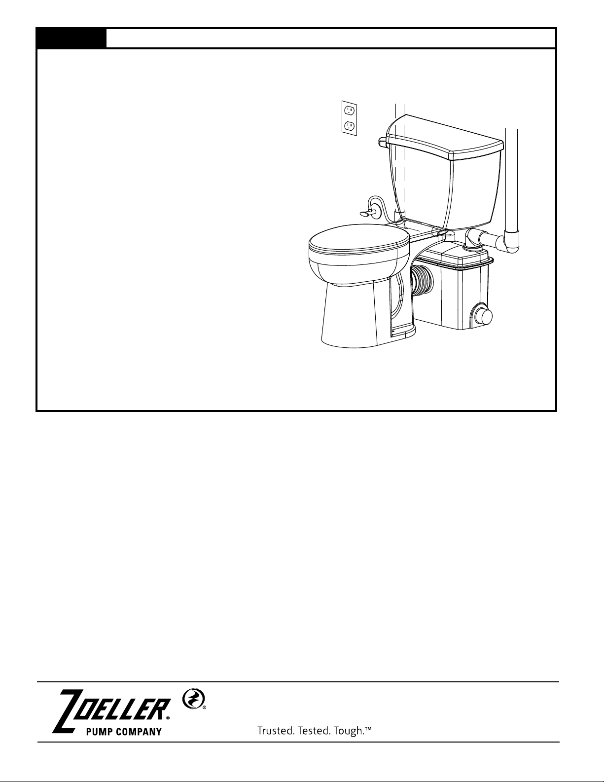
1. This unit is not designed to handle any material other than human waste
and toilet paper. The list of items that should not be used with this system
includes, but is not limited to: feminine sanitary products, condoms, cotton
balls and swabs, baby wipes, paper towels, etc.
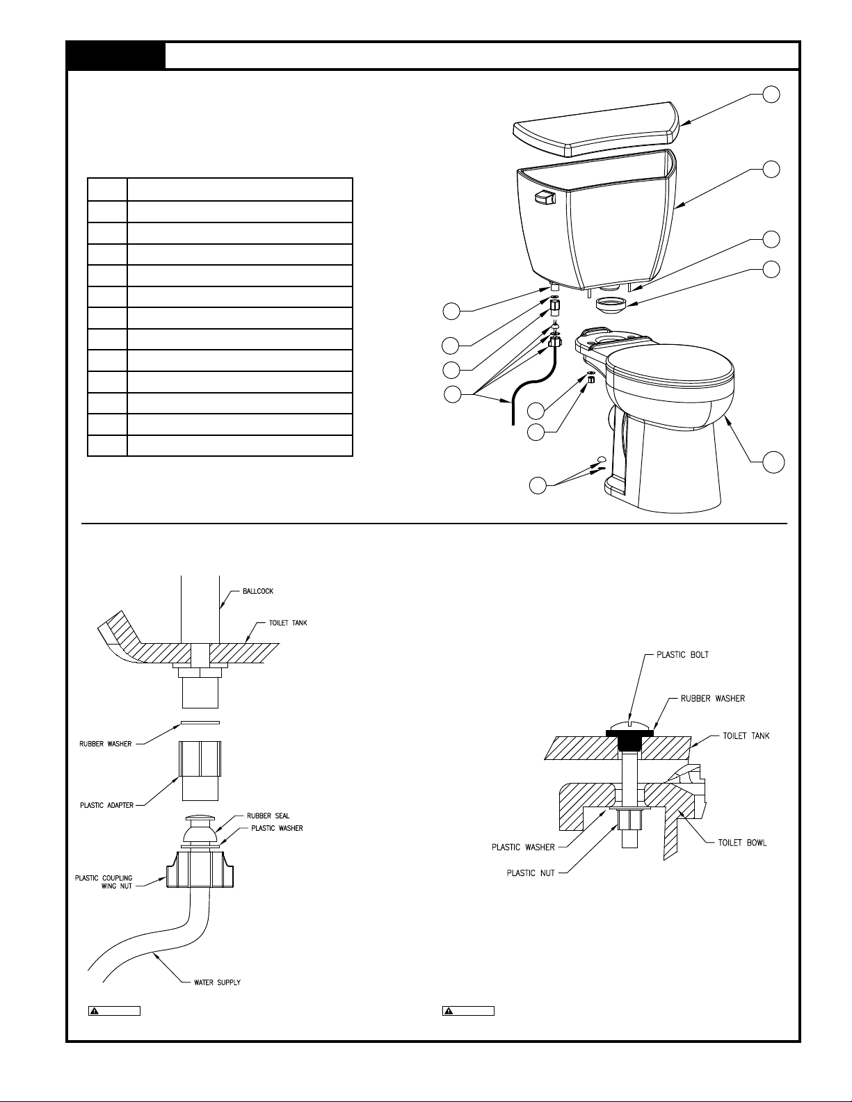
2. All plumbing (discharge and vent lines) must be installed to meet local codes.
Unit must be vented. Do not use an automatic plumbing vent device. Toilet
will not ush.
3. Maximum operating liquid temperature for model 202 must not exceed
130 °F (54 °C).
4. Do not use cleaning products containing bleach in the toilet tank, toilet or
attached xtures as they will degrade the pump seals.
5. Accordingto the stateof California (Prop 65), thisproduct contains chemicals
known to the state of California to cause cancer and birth defects or other
reproductive harm.
6. Risk of explosion. Do not use the pump for ammable liquids such as diesel
oil, petrol or similar liquids.
SEE BELOW FOR
LIST OF NOTES
NOTES
1. Repair and service should be performed by an Authorized Service and
Warranty Center only (consult factory).
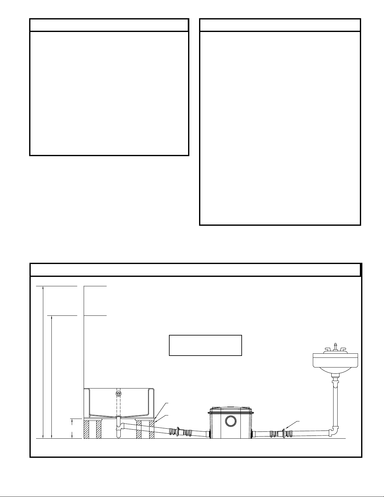
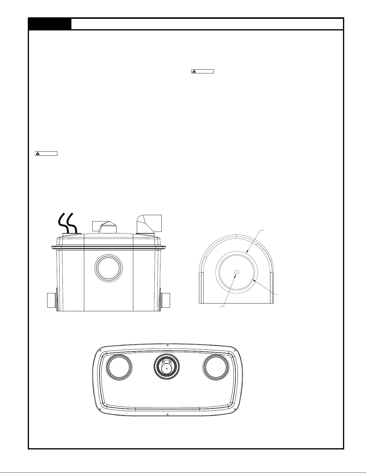
2. Recommended for installations up to 20' (6 m) total dynamic head. Consult
Factory if installation is above 15' (5 m) vertical height in 1" (DN25) pipe.
Mini-grinder pump is designed for use in Qwik Jon®Ultima units only. It is
not designed for use in any other application.
3. Mini-grinder pump is rated for 115 V, 60 Hz, 7 Amps, 1/2 HP.
4. Pumps with the “UL” mark and pumps with the “US” mark are tested to
UL Standard UL778. CSA Certied pumps are certied to CSA Standard
C22.2 No. 108. Qwik Jon®Ultima units only. It is not designed for use in
any other application.
5. Model 202 toilet utilizes 1.28 or 1.6 gallons (4.8 or 6.1 liters) per ush.
6. All xtures connecting to the system must be on the same oor level.
CAUTION
SEE BELOW FOR
LIST OF CAUTIONS

3
© Copyright 2017 Zoeller®Co. All rights reserved.
Helpful Hints For Easy Installation
1. Read all instructions before beginning installation.
2. Be sure the oor is level within 1/8" (3 mm).
3. Install vent pipe seal with ange side of seal on outside of lid.
4. Use soapy water to lubricate all seals to aid
installation.
5. Install rubber coupling/union in vent line to aid disassembly.
6. Do not over torque toilet mounting screws.
7. Do not use an automatic plumbing vent device.
8. Obtain model number and date code, and record information
in the space provided on the front of this manual. Refer to this
information when calling factory.
Do’s And Don't’s For Installing A Unit
1. DO read all installation material with the unit.
2. DO inspect unit for any visible damage caused by shipping.
Contact dealer if unit appears to be damaged.
3. DO clean all visible debris from the unit.
4. DO always disconnect pump from power source before handling.
DO always connect to a separately protected and properly
grounded ground fault protected circuit. DO NOT ever cut, splice
or damage power cord. DO NOT carry or lift pump by its power
cord. DO NOT use an extension cord.
5. DO install a ball or gate valve and a union in the discharge line
downstream of the check valve.
6. DO test pump immediately after installation to be sure that the
system is working properly.
7. DO review all applicable local and national codes and verify that
the installation conforms to each of them.
8. We DO NOT recommend this product be connected to utilities
otherthanthosefoundinanormalbathroomapplication.Washing
machines and dishwashers are examples of equipment that we
DO NOT recommend.
9. DO inspect and test system for proper operations at least every
3 months.
Typical Piping Congurations
NOTE: All installations must comply with all applicable Electrical
and Plumbing Codes, including, but not limited to, National
Electrical Code, Local, Regional and/or State Plumbing Codes, etc.
SK2587
8’ (2.4 m) CEILING
7’ (2.1 m) CEILING
8" (203 mm)
MIN
2” x 8” (51 x 203 mm)
FLOOR JOISTS
SUBFLOOR 3/4" (19 mm)
THICK MINIMUM.
CHECK VALVE
P/N 30-0181
Installation may not
be exactly as shown.

4
© Copyright 2017 Zoeller®Co. All rights reserved.
9
8
7
3
1
2
4
10
5
6
11
12
13
14
15
16
Service Parts
QWIK JON®ULTIMA
202-A & B 202-C
10/06 thru
5/16
6/16 thru
Current
Item Description Part No. Part No.
1 Qwik Jon®Ultima sewage removal system 202-1000 202-1000
2 Replacement pump with discharge pipe 017374 152165
3Tank cover with discharge ttings 017373 017373
4 Tank 018500 018500
5 Seal 017350 017350
6 Float switch assembly 018501 018501
7 Toilet bowl 202-2000 202-2000
8
Toilet tank with cover 1.6 GPF (6.1 LPF) (left handed) 202-3000 N/A
Toilet tank with cover 1.6 GPF (6.1 LPF) (right handed) 202-3001 N/A
Toilet tank with cover 1.28 GPF (4.8 LPF) (left handed) N/A 202-3002
Toilet tank with cover 1.28 GPF (4.8 LPF) (right handed) N/A 202-3003
9 Toilet tank cover 150012 154032
10 Rubber coupling with hose clamps 151563 151563
11 Extension kit for behind the wall installation 10-3050 10-3050
12 Tank-to-toilet hardware 017360 154048
13 Flush valve replacement kit - 1.6 GPF (6.1 LPF) 150658 N/A
Flush valve replacement kit - 1.28 GPF (4.8 LPF) N/A 152587
14 Fill valve assembly with tube - 1.6 GPF (6.1 LPF) 150823 N/A
Fill valve assembly with tube - 1.28 GPF (4.8 LPF) N/A 152588
15 Flush valve assembly 150824 154029
16 Flapper with clip and chain 150825 N/A
SK2605

5
© Copyright 2017 Zoeller®Co. All rights reserved.
Condition Possible Cause Remedy
PUMP WILL NOT START OR RUN.
Low voltage, blown fuse, open
circuit
Have a qualied electrician check fuse
and circuit.
Impeller bound Contact a Zoeller Service Center.
Motor or wiring shorted
Debris on oat switch Remove debris
PUMP STARTS TOO SOON. Float“ON”pointisadjustedtoolow Raise the oat stops, make sure the
oat is between the two stops.
WATER LEVEL EXCESSIVE BEFORE
PUMP TURNS ON. Float “ON” point adjusted to high Lower the upper oat stop.
PUMP WILL NOT SHUT OFF OR
RUNS TOO LONG BEFORE WATER
IS PUMPED.
Pump not plugged into piggyback
oat switch receptacle
Ensure pump is not plugged directly
into the outlet. Plug pump into
piggyback oat switch receptacle.
Debris under oat Remove debris from around oat.
Faulty oat switch Contact a Zoeller Service Center.
Float “OFF” point adjusted too low Raise the lower oat stop.
Pump is air locked Make sure vent hole in discharge
pipe is clear.
Water level too low Raise the lower oat stop.
Waste material has accumulated
blocking ow of material
Hold ush handle down on toilet
for 15 seconds. If unit will not clear,
unplug and wait 30 minutes. Plug
unit back in and repeat. If unit still
will not turn off, it will need to be
opened and the debris relocated.
PUMP OPERATES BUT DELIVERS
LITTLE OR NO WATER.
Debris around intake Clean area around intake.
Blockage in discharge pipe Remove pipe and ush out debris.
Low or incorrect voltage Have a qualied electrician check
house wiring.
Damaged Impeller Contact a Zoeller Service Center.
Incorrect oat adjustment Contact Product Support
Department.
Pump is air locked Make sure vent hole in discharge
pipe is clear.
Vertical lift too high Change discharge piping or contact
Product Support Department.
Before servicing a pump, always shut
off the main power breaker and then unplug the
pump - making sure you are not standing in water
and are wearing insulated protective sole shoes.
Under ooded conditions, contact your local electric
company or a qualied licensed electrician for disconnecting
electrical service prior to pump removal.
Submersible pumps contain oil which become
pressured and hot under operating conditions. Allow 2-1/2
hours after disconnecting before attempting service.
If the above checklist does not solve the problem, consult
Zoeller Product Support Department 1 (800) 928-7867 or
1(502) 778-2731- Do not attempt to service or otherwise
disassemble pump.
CAUTION
Do not dispose of feminine sanitary products,
disposable diapers, dish rags, etc. in the QWIK JON®
ULTIMA . They may jam the pump or other plumbing lines
and cause malfunction.
CAREOF FINISH:Soap and wateris all that is recommended
for cleaning the outside of the tank. Other cleaning products
may cause discoloration and scratching.

6
© Copyright 2017 Zoeller®Co. All rights reserved.
Qwik Jon®Ultima Qwik Reference Guide
STEP 1 Location Selection
Plan your new installation carefully.
Floor: The oor should be structurally sound
and level within 1/8" (3 mm). If the oor is not
level, use hydraulic cement or similar material
to level the oor.
Water: A water supply will be needed to
operate the toilet. Usually a 1/2" (DN15) line
with a shut-off valve is sufcient.
Electrical: A115 volt GFCI or RCD receptacle
will be needed to supply electrical power to
the pump.
Sewage: Access to a sewage line is required.
The Qwik Jon®Ultima requires a 1" (DN25)
[or 3/4" (DN20) if your codes permit] sewage
discharge line to connectto an existing sewage
line. A ball or gate valve should be installed in
the discharge line.
Vent: Access to a vent pipe is required. The
use of a mechanical vent system is NOT
recommended as the toilet will not ush.
NOTE: If a built-in installation is to be used,
locate the pump unit in an area that will allow
access to the pump and switch.
GFCI
OUTLET
WATER
SUPPLY
DISCHARGE
PIPE
VENT
PIPE
LEVEL FLOOR
BALL OR GATE VALVE
SOLD SEPARATELY.
SK2588
STEP 2 Leveling of Pump Unit
CAUTION
Do not use wooden shims to level the pump unit!
CAUTION
Ensure that nails, screws or other sharp objects do
not puncture the pump unit!
Level the pump unit to within 1/8" (3 mm) using hydraulic cement
or similar material.
SK2589

7
© Copyright 2017 Zoeller®Co. All rights reserved.
NOTES:
a) Do not use pipe dope on any plastic or rubber parts.
b) Be careful when tightening bolts or nuts against china to
avoid cracking the china.
STEP 3 Toilet Assembly
1
2
3
4
12
10
7
6
5
8
9
11
SK2593
TANK TO BOWL DETAILWATER SUPPLY HOOK-UP DETAIL
Set the black rubber washer.
Push down on the top of the tank one side at a time to
tighten the nuts under the bowl. Alternate tightening nuts
making sure bowl is level.
DO NOT OVERTIGHTEN or china may crack.
CAUTION
CAUTION
DONOTOVERTIGHTEN.Ballcock shank
may split and void the warranty.
SK2594
Item Description
1 Toilet tank cover
2 Toilet tank
3 Toilet tank to toilet bowl gasket bolts
4 Rubber toilet tank to toilet bowl gasket
5 Water supply connection
6 Water supply line rubber seal
7 Water supply line adapter
8 Water supply line (not included)
9Plastic at washer
10 Plastic nut
11 Bolt cover
12 Toilet bowl

8
© Copyright 2017 Zoeller®Co. All rights reserved.
STEP 4 Rough-in (stand-alone installation)
1) Position the pump unit a minimum of 1/8" (3 mm)
from the wall with the inlet facing forward. Attach
the bellows to the inlet using the worm drive clamp
provided.
2) Place the toilet in front of pump unit aligning the
discharge of the toilet with the inlet of the pump
unit. Make sure that the bellows will bridge the gap
adequately for nal installation. The toilet tank should
be a minimum of 1/2" (13 mm) from the wall.
SK2590
3) Lightly mark the locations of the pump unit, toilet
and closet bolt locations on the oor. Lightly mark
the wall with the height of the pump unit and the
bottom and sides of thetoilet tank to ensure against
interference from pipe runs later.
4) Remove the toilet from the pump unit and set it
aside.
17-1/2”
(445 mm)
31-1/2”
(800 mm)
14-3/8”
(365 mm)
20” (508 mm)
SK2592
STEP 5 Rough-in (behind-the-wall installation)
1) Installing the grinder unit behind a wall will require
an extension kit (P/N 10-2123) sold separately.
2) Place the toilet assembly a minimum of 1/2" (13 mm)
from the wall and mark the closet bolt locations on
the oor.
3) Measure the appropriate length of 3-1/2" (DN95)
Schedule 40 PVC pipe provided with the extension
kit and cut it to length. See sketch at right.
4) Set toilet aside.
CAUTION
Toilet assembly is top heavy. Take special
precautions to ensure that toilet does not tip over and
break. SK2634

9
© Copyright 2017 Zoeller®Co. All rights reserved.
STEP 6 Piping
1) Cut and dry-t the pipe and ttings as required for
1" (DN25) diameter discharge pipe (may be reduced
to 3/4" [DN20] diameter if codes permit).
2) While dry-tting the discharge pipe, position and
mark the location of the pump unit discharge tting.
3) Cut and dry-t 1-1/2" (DN40) vent pipe as required
to ensure that the vent pipe does not interfere with
other components. Make the connection to the pump
unit with the provided street elbow. A 2" x 1" (DN50
x DN25) 90° discharge tting and a 1-1/2" (DN40)
street elbow vent tting have been provided for space
constraints in a stand alone conguration. However,
these are not required for a built-in installation. It
will reduce Total Dynamic Head on the system and
simplify assembly on a built-in installation to utilize
straight pipe. For the discharge pipe, use a 2" (DN50)
straight coupling and reduce it down to 1" (DN25).
CAUTION
Proper venting is required for the toilet to ush.
Do not use a mechanical type vent.
4) Temporarily set the toilet in place to check that there
is no piping interference. Remove the toilet and set
it aside.
5) Clean, prime and solvent weld the discharge piping
and pump unit discharge tting.
CAUTION
When applying solvent weld to discharge tting,
ensure that none gets into the check valve assembly. Pay
close attention to the proper alignment of the discharge
tting previously marked above.
6) Clean and solvent weld vent piping as required for
proper venting.
Note: Adding other bathroom xtures - The Qwik Jon®
Ultima is designed to accept additional bathroom xtures
utilizing the two side inlets. These inlets can be attached
via the 2" MPT (outside diameter) or the 1-1/2" (DN40)
slip (inside diameter). These inlets must have the inner
portion drilled out using a 1-3/4" (44 mm) hole saw. This
is to ensure there is no leakage problems from inlets not
in use. When utilizing side inlets, install a check valve on
the incoming line.
SK2591
DRILL POINT
1-1/2" (DN40) SLIP INSIDE
2" MPT OUTSIDE
SK2586SK2589

10
© Copyright 2017 Zoeller®Co. All rights reserved.
1) Install the closet bolts at the points marked earlier.
2) Place the toilet assembly over the closet bolts. Install
the anchoring hardware and tighten in an alternating
pattern. Check for level and shim as required. Be
careful when tightening bolts or nuts against china
to avoid cracking the china.
3) Install rubber bellows onto the toilet discharge and
grinder tank hub and secure with the worm clamps
provided for stand alone installation. See sketch
in Step 4. For built-in installation, install the rubber
couplings to both the grinder tank and the toilet
discharge and secure to extension pipe with worm
clamps provided. See sketch in Step 5.
4) Install the water supply line from the existing water
shut-off valve to the toilet water supply connection.
5) Open the water supply valve and check for leaks.
The toilet tank should ll to the proper level. Adjust
if required.
6) Plug the pump's power cord into the piggyback switch
receptacle and then plug the piggyback switch into
the GFCI outlet.
7) Flush the toilet and watch for proper operation. Listen
for the pump to start. The pump unit requires proper
venting in order for toilet to ush. Check for leaks.
8) Repeat ush cycles to assure proper operation.
9) Install an elongated toilet seat (supplied by
others).
10) Install the lid on the toilet tank.
FLOOR LEVEL TO WITHIN 1/8" (3 mm)
PUMP UNIT
AUX. INLET
WATER
SUPPLY
GFCI
OUTLET
DISCHARGE
PIPE VENT PIPE
(PER ALL CODES.
DO NOT USE
MECHANICAL VENT)
SK2595
STEP 7 Toilet Installation
MAIL TO: P. O . BOX 16347 • Louisville, KY 40256-0347
SHIP TO: 3649 Cane Run Road • Louisville, KY 40211-1961
(502) 778-2731 • 1 (800) 928-PUMP • FAX (502) 774-3624 Visit our web site:
zoellerpumps.com
These are the original installation instructions.

11
Aviso al contratista instalador: Las instrucciones deberán permanecer con la instalación.
FM2369S
SISTEMAS QWIK JON® ULTIMA 202
INSTRUCCIONES DE INSTALACIÓN
!
ADVERTENCIA
La información presentada
adentro reeja condiciones al
tiempo de publicación. Consultar
la fábrica sobre discrepancias o
contradicciones.
DIRECCIÓN POSTAL: P.O. BOX 16347 • Louisville, KY 40256-0347 EEUU
DIRECCIÓN PARA ENVÍOS: 3649 Cane Run Road • Louisville, KY 40211-1961 EEUU
TEL: +1 (502) 778-2731 • FAX: +1 (502) 774-3624
Visite a nuestro sitio web:
zoellerpumps.com
Confiable. Probado. Resistente.™
No. DE MODELO: _______________
CÓDIGO DE FECHA:_____________
FECHA DE INSTALACIÓN: _______
1. Inspeccione todos materiales. Ocasionalmente, los productos se dañan durante el embarque. Si la unidad está dañada, comuníquese con el distribuidor
antes de usarla. No quite los conectores de prueba de la bomba.
2. Lea cuidadosamente toda la literatura que se le entregó para familiarizarse con los detalles especícos de instalación y uso. Conserve estos materiales
para futuras referencias.
N/P 018507
© Copyright 2017 Zoeller®Co. Todos los derechos reservados.
1. Para reducir el riesgo de electrocución debe instalarse un receptáculo o caja
de control con conexión a tierra, mismo(a) que deberá protegerse mediante
un interruptor de circuito por falla a tierra (GFCI, por sus siglas en inglés) de
conformidad con el Código Eléctrico Nacional de los Estados Unidos y los
códigos locales aplicables. No quite la clavija de conexión a tierra del enchufe.
2. Asegúrese de que el tomacorriente o caja de control esté al alcance del cable
de alimentación eléctrica de la bomba. NO USE UN CABLE DE EXTENSIÓN.
Los cables de extensión que son demasiado largos o livianos no suministran
voltaje suciente al motor de la bomba y presentan un peligro a la seguridad si
el aislante se daña o el extremo de conexión cae dentro de una área mojada.
3. Asegúrese de que el circuito de alimentación eléctrica de la bomba esté
equipado con fusibles o disyuntores con capacidad adecuada. Se recomienda
un circuito derivado del tamaño que se indica en el Código Eléctrico Nacional
de los Estados Unidos para la corriente detallada en la placa de características
de la bomba.
4. Pruebe la tierra. Como medida de seguridad, la tierra de todos los
tomacorrientes debe revisarse con ayuda de un multímetro aprobado por
la Underwriters Laboratory que indique si el cable de alimentación, el cable
neutral y el cable de la tierra están debidamente conectados al tomacorriente.
Si no lo están, llame a un electricista calicado.
5. POR PROTECCIÓN, SIEMPRE DESCONECTE LABOMBAY DE LAFUENTE
DEALIMENTACIÓN ANTES DE MANIPULARLA. Si el cableado de la bomba
es directo, desenergice el circuito desde la caja de controles. Las bombas
aterrizadas cuentan con un enchufe aterrizado de tres clavijas, a n de
ayudarle a protegerse contra la posibilidad de que ocurra un choque eléctrico.
POR NINGÚN MOTIVO DEBERÁ QUITARLE LA CLAVIJA DE CONEXIÓN
A TIERRA AL ENCHUFE. Para ayudar a reducir el riesgo de electrocución
debe instalarse un receptáculo con conexión a tierra, mismo(a) que deberá
protegerse mediante un interruptor de circuito por falla a tierra (GFCI, por sus
siglas en inglés o RCD) de conformidad con el Código Eléctrico Nacional de
los Estados Unidos y los códigos locales aplicables.
6. La instalación y el servicio de los circuitos eléctricos y aditamentos deberá
hacerla un electricista debidamente calicado y certicado.
7. Asegúrese de que la fuente de energía eléctrica sea capaz de manejar lose
requisitos de amperaje del motor, según se indica en la placa de indenticación
de la bomba.
VER ABAJO LA LISTA DE ADVERTENCIAS
INSTRUCCIONES DE SEGURIDAD
LISTA DE CONTROL PREVIA A LA INSTALACIÓN
REFIÉRASE A LAS PRECAUCIÓNES Y LA GARANTÍA EN LA PÁGINA 12.
PARA EVITAR LESIONES PERSONALES GRAVES O FATALES O
DAÑOSIMPORTANTESALAPROPIEDAD,LEAYCUMPLATODASLAS
INSTRUCCIONESDESEGURIDADDEESTEMANUALYDELABOMBA.
ESTEMANUALTIENE POR OBJETIVOAYUDARENLAINSTALACIÓNY
OPERACIÓNDEESTAUNIDADYDEBEPERMANECER JUNTOAELLA.
Este símbolo signica una ALERTA DE SEGURIDAD.
Al ver este símbolo en la bomba o el manual, buscar
una de las siguientes palabras de advertencia y ponerse
sobre aviso de posibles lesiones personales o daños a
la propiedad.
Advierte de peligros que PODRÍAN ocasionar graves
lesiones personales, la muerte o daños importantes a
la propiedad.
Advierte de peligros que PODRÍAN ocasionar lesiones
personales o daños a la propiedad.
AdviertedepeligrosdedescargaseléctricasquePODRÍAN
ocasionar graves lesiones personales, la muerte o daños
importantes a la propiedad.
Identica cualquier terminal con su conexión determinada
y los conductores externos para la protección contra
descargas eléctricas en caso de un fallo o el terminal de
un electrodo de tierra de protección (tierra).
Lea el manual del operador.
REVISE A FONDO TODAS LAS INSTRUCCIONES Y ADVERTENCIAS
ANTES DE LLEVAR A CABO NINGÚN TRABAJO CON ESTA BOMBA.
MANTENGA TODAS LAS CALCOMANÍAS DE SEGURIDAD.
!
ADVERTENCIA
!
PRECAUCIÓN
Registre en línea
su producto de
Zoeller Pump Company:
http://reg.zoellerpumps.com/
Patente nos. de EEUU
7,203,976; 9,352,327;
8,562,287
Patente nos. de Canada
2,512,023

12
Duranteelperiododegarantía,elfabricantegarantizaalcompradorypropietario
subsiguiente, que todos los productos nuevos están libre de defectos en
cuanto a sus materiales y manufactura bajo condiciones de uso y servicio
normales, siempre y cuando se usen y mantengan adecuadamente, durante
un periodo de un año a partir de la fecha en que los haya adquirido el usuario
nal, o bien, 18 meses a partir de la fecha de fabricación original del producto,
lo que suceda primero. Todas las piezas que dejen de funcionar durante el
periodo de garantía (un año a partir de la fecha en que los haya adquirido el
usuario nal, o bien, 18 meses a partir de la fecha de fabricación original del
producto,loquesucedaprimero)yquemediante una inspección se determine
queson defectuosasen cuanto a sus materiales o manufactura, se repararán,
reemplazarán o volverán a fabricar a opción del fabricante, siempre y cuando
esto no implique ninguna obligación de reemplazar un montaje entero, el
mecanismo entero o la unidad completa. No se hará ningún reembolso por
gastos de envío, daños, mano de obra u otros cargos que pudieran resultar
de la falla, reparación o reemplazo del producto.
No se otorgará garantía alguna por ningún material o producto que se haya
desarmado sin la aprobación previa del fabricante, o que haya sido sujeto a
algún uso indebido, aplicación indebida, negligencia, alteración, accidente o
acto fortuito; que no se haya instalado, usado o mantenido de acuerdo a las
instrucciones de instalación proporcionadas por el fabricante; que se haya
expuesto a sustancias ajenas, incluyendo, de manera enunciativa mas no
limitativa, lo siguiente: arena, grava, cemento, lodo, brea, hidrocarburos,
derivadosdehidrocarburos(aceite,gasolina,solventes,etc.)uotrassustancias
abrasivas o corrosivas, toallas húmedas o productos de higiene femenina,
etc., en todas las aplicaciones de bombeo. La garantía expuesta en el párrafo
anterior sustituye a todas las demás garantías expresas o implícitas y no
autorizamos a ningún representante u otra persona para que asuma ninguna
otraresponsabilidad anuestro nombre y en conexión con nuestros productos.
Envíe su correspondencia dirigida al fabricante a la siguiente dirección: 3649
Cane Run Road, Louisville, Kentucky 40211 EEUU, Atención: Departamento
de Atención a Clientes, para obtener la(s) reparación(es) o refacción(es)
necesaria(s) o información adicional sobre la garantía.
EL FABRICANTE SE DESLINDA EXPRESAMENTE DE TODA
RESPONSABILIDAD POR DAÑOS ESPECIALES, EMERGENTES
O INCIDENTALES O POR INCUMPLIMIENTO DE LA GARANTÍA
EXPRESA O IMPLÍCITA. ASIMISMO, TODA GARANTÍA IMPLÍCITA DE
COMERCIABILIDAD O APTITUD PARA UN FIN DETERMINADO SE
LIMITARÁ A LA DURACIÓN DE LA GARANTÍA EXPRESA.
Algunos estados no permiten que se limite la vigencia de una garantía
implícita por lo que es posible que la limitación anterior no le corresponda.
Algunos estados no permiten que se excluyan o limiten los daños incidentales
o emergentes, por lo que es posible que la limitación o exclusión anterior no
le corresponda.
Esta garantía le otorga derechos legales especícos y es posible que le
correspondan otros derechos que varían de un estado a otro.
Garantía limitada
© Copyright 2017 Zoeller®Co. Todos los derechos reservados.
VER ABAJO LA LISTA
DE AVISOS
VER ABAJO LA LISTA
DE PRECAUCIONES
AVISO
1. Esta unidad no está diseñada para manejar materiales que no sean
desechos humanos o papel sanitario. La siguiente lista incluye, de
manera enunciativa mas no limitativa, artículos que no deberán usarse
en este sistema: productos para la higiene femenina, condones,
torundas e hisopos de algodón, toallitas húmedas para bebé, toallas
de papel, etc.
2. Toda la tubería (líneas de descarga y ventilación) debe instalarse de
conformidad con los códigos locales. La unidad debe estar ventilada.
No use dispositivos automáticos de ventilación para tuberías. Estos
impiden el funcionamiento del inodoro.
3. La temperatura máxima de funcionamiento del modelo 202 no deberá
exceder los 54 ºC (130 ºF).
4. No use productos que contengan cloro para limpiar el tanque del
inodoro, el inodoro ni sus aditamentos, ya que desgastan los sellos de
la bomba.
5. Este producto contiene sustancias químicas que de acuerdo al estado
de California (Prop 65) pueden causar cáncer y defectos congénitos u
otros daños a la salud reproductiva.
6. Riesgo de explosión. No use la bomba para líquidos inamables como
gasóleo, petróleo o líquidos similares.
1. La reparación y el servicio deberán hacerse únicamente a través de una
estación de servicio autorizada por Zoeller Pump Company (consulte al
fabricante).
2. Se recomienda para instalaciones con una carga dinámica total de
hasta 6 m (20 pies). Consulte al fabricante si la instalación tiene una
altura vertical de más de 5 m (15 pies) en una tubería de DN25 (1
pulg). La minibomba trituradora está diseñada para usarse únicamente
en combinación con las unidades Qwik Jon®Ultima. No está diseñada
para usarse en ninguna otra aplicación.
3. La minibomba trituradora está certicada para especicaciones de
115 V, 60 Hz, 7 A, 1/2 HP.
4. Las bombas que ostentan los símbolos “UL” y “US” están probadas de
conformidad con la norma UL778 de la UL. Las bombas certicadas por
la CSA están probadas de conformidad con la norma C22.2 No.108.
de la CSA. Solo aplica para las unidades Qwik Jon®Ultima. No están
diseñadas para usarse en ninguna otra aplicación.
5. El inodoro modelo 202 consume 4.8 o 6.1 litros (1.28 o 1.6 galones) de
agua cada vez que se acciona.
6. Todos los aditamentos conectados al sistema deberán estar al mismo
nivel del suelo.
!PRECAUCIÓN

13
Sugerencias útiles para facilitar la instalación
1. Lea todas las instrucciones antes de iniciar la instalación.
2. Asegúrese de que el piso esté nivelado y no tenga una pendiente de
más de 3 mm (1/8 pulg).
3. Instaleelsellodeltubodeventilaciónconlabridahaciaafueradelatapa.
4. Use agua jabonosa para lubricar todos los sellos y facilitar su
instalación.
5. Instale una conexión o unión de hule en la línea de ventilación para
facilitar su desmontaje.
6. No apriete demasiado los tornillos de montaje del inodoro.
7. No use dispositivos automáticos de ventilación para tuberías.
8. Anote el número de modelo y el código de fecha en el espacio
dispuesto para este n en la carátula de este manual. Proporcione
esta información cuando se comunique con el fabricante.
1. LEA todos los materiales de instalación que acompañan la unidad.
2. REVISE la unidad para ver si hay algún signo visible de daños
ocasionados durante el embarque. Comuníquese con el proveedor
si la unidad parece estar dañada.
3. RETIRE todos los desechos visibles que tenga la unidad.
4. DESCONECTE siempre la bomba de la fuente de poder antes de
manipularla. CONÉCTELA siempre a un circuito independiente
debidamente aterrizado y protegido mediante un interruptor de
circuito por falla a tierra. NO corte, empalme ni dañe nunca el cable
de alimentación. NO cargue ni levante la bomba jalándola del cable
de alimentación. NO use extensiones.
5. INSTALE una válvula de bola o de compuerta y una unión en la línea
de descarga, antes de la válvula de retención, en el sentido del ujo
descendente.
6. PRUEBE la bomba inmediatamente después de instalarla, para
asegurarse de que el sistema funciona adecuadamente.
7. REVISEtodosloscódigoslocalesynacionalesaplicablesyasegúrese
de que la instalación cumpla con todos ellos.
8. NO recomendamos que este producto se conecte a otros servicios
distintos a los que se encuentran en una aplicación normal para
baños. Las lavadoras y lavavajillas son ejemplos de equipos que
NO recomendamos.
9. REVISE y pruebe el debido funcionamiento del sistema por lo menos
cada 3 meses.
Conguraciones de plomería típicas
NOTA: Todas las instalaciones deben cumplir con todos los
códigos eléctricos y de plomería aplicables, incluyendo de manera
enunciativa pero no limitativa, el Código Eléctrico Nacional de
los Estados Unidos y los códigos para instalaciones sanitarias
regionales, municipales y/o estatales, etc.
SK2587
ALTURA AL TECHO DE 2.4 M (8 PIES)
ALTURA AL TECHO DE 2.1 M (7 PIES)
203 mm
(8 PULG.) MÍN
VIGA DEL SUELO DE
51 x 203 MM (2 x 8 PULG.)
SUBSUELO DE 19 mm
(3/4 PULG.) MÍN
VALVULA DE
RETENCIÓN
N/P 30-0180
Lainstalaciónpodría no ser
exactamente igual a la que
se ilustra aquí.
© Copyright 2017 Zoeller®Co. Todos los derechos reservados.
Qué hacer o evitar al instalar una unidad

14
© Copyright 2017 Zoeller®Co. Todos los derechos reservados.
9
8
7
3
1
2
4
10
5
6
11
12
13
14
15
16
Partes para servicio
QWIK JON®ULTIMA
202-A y B 202-C
10/06
á
5/16
6/16
á
Presente
Pieza Descripción Numéro de
parte
Numéro de
parte
1 Sistema de remoción de aguas negras Qwik Jon®Ultima 202-1000 202-1000
2 Bomba de reemplazo con tubo de descarga 152168 152165
3 Tapa del tanque con conexiones de descarga 017373 017373
4 Tanque 018500 018500
5 Sello 017350 017350
6Conjunto del interruptor de otador 018501 018501
7 Taza del inodoro 202-2000 202-2000
8
Tanque del inodoro con cubierta - 6.1 L por descarga (1.6 gpd) (para zurdos) 202-3000 --
Tanque del inodoro con cubierta - 6.1 L por descarga (1.6 gpd) (para diestros) 202-3001 --
Tanque del inodoro con cubierta - 4.8 L por descarga (1.28 gpd) (para zurdos) -- 202-3002
Tanque del inodoro con cubierta - 4.8 L por descarga (1.28 gpd) (para diestros) -- 202-3003
9 Cubierta del tanque del inodoro 150012 154032
10 Conexión de hule con abrazaderas de manguera 151563 151563
11 Juego de extensión para instalación detrás de la pared 10-3050 10-3050
12 Aditamentos para jar el tanque al inodoro 017360 154048
13 Juego para reemplazo de la válvula de descarga - 6.1 L por descarga (1.6 GPD) 150658 --
Juego para reemplazo de la válvula de descarga - 4.8 L por descarga (1.28 GPD) -- 152587
14 Conjunto de la válvula de llenado con tubo - 6.1 L por descarga (1.6 GPD) 150823 --
Conjunto de la válvula de llenado con tubo - 4.8 L por descarga (1.28 GPD) -- 152588
15 Conjunto de la válvula de descarga 150824 154029
16 Sapo con clip y cadena 150825 --
SK2605

15
Problema Causa probable Solución
LA BOMBA NO ENCIENDE O NO
FUNCIONA.
Hay bajo voltaje, un fusible quemado o un
circuito abierto.
Pídale a un electricista calicado que revise el fusible
y el circuito.
El impulsor está pegado. Comuníquese con una estación de servicio autorizada
por Zoeller.
Hay un corto circuito en el motor o el
cableado.
Hay escombros encima del interruptor de
otador. Retire los desechos.
LA BOMBA SE ENCIENDE MUY
PRONTO.
El punto de encendido "on" del otador está
ajustado muy abajo.
Coloque los topes del otador más arriba y asegúrese
de que el otador esté entre los dos topes.
LA BOMBA NO SE ENCIENDE SINO
HASTA QUE EL NIVEL DEL AGUA ES
MUY ELEVADO.
El punto de encendido "on" del otador está
ajustado muy arriba. Baje el tope superior del otador.
LABOMBANO SEAPAGAO FUNCIONA
DURANTE MUCHO TIEMPOANTES DE
EMPEZAR A BOMBEAR AGUA.
La bomba no está conectada al receptáculo
del interruptor de otador con enchufe en
tandem.
Revise que la bomba no esté conectada directamente
al tomacorriente. Conecte la bomba al receptáculo del
interruptor de otador integrado.
Hay escombros debajo del otador. Quite los desechos que haya alrededor del otador.
El interruptor de otador está defectuoso. Comuníquese con una estación de servicio autorizada
por Zoeller.
El punto de apagado "off" del otador está
ajustado muy abajo. Suba el tope inferior del otador.
Hay aire atrapado dentro de la bomba. Verique que el respiradero del tubo de descarga no
esté obstruido.
El nivel del agua está muy bajo. Suba el tope inferior del otador.
Hay desechos acumulados que están
bloqueando el ujo de materiales.
Baje la palanca del inodoro y sosténgala en esa
posición durante 15 segundos. Si la unidad no se
desatasca, desconéctela y espere 30 minutos. Vuelva
a conectar la unidad y repita la operación. Si la
unidad no se apaga, tendrá que abrirla y mover los
desechos.
LABOMBAFUNCIONAPEROPROCESA
MUY POCA AGUA O NADA.
Hay desechos alrededor del punto de
entrada. Limpie alrededor del punto de entrada.
El tubo de descarga está bloqueado. Quite el tubo y enjuáguelo para eliminar los desechos.
El voltaje es muy bajo o incorrecto. Pídale a un electricista calicado que revise el
cableado de la casa.
El impulsor está dañado. Comuníquese con una estación de servicio autorizada
por Zoeller.
El otador está mal ajustado. Comuníquese con el Departamento de Apoyo con
Productos
Hay aire atrapado dentro de la bomba. Verique que el respiradero del tubo de descarga no
esté obstruido.
La elevación vertical es excesiva. Cambie la tubería de descarga o comuníquese con el
Departamento de Apoyo con Productos.
!
ADVERTENCIA
Antes de darle mantenimiento a la bomba,
siempre apague el interruptor de energía principal y
luego desconecte la bomba. Use calzado con suela
protectora aislante y asegúrese de no estar pisando agua. En
caso de inundación, comuníquese con la compañía eléctrica
local o con un electricista debidamente calicado y autorizado
para desconectar el suministro eléctrico antes de sacar la bomba.
!
ADVERTENCIA
Las bombas sumergibles contienen aceites que se
presurizan y calientan bajo condiciones de operación. Deje que
transcurran 2-1/2 horas después de la desconexión antes de
iniciar el mantenimiento.
Si esta lista no le ayuda a identicar el problema, comuníquese
con el Departamento de Apoyo con Productos de Zoeller al
+1 (502) 778-2731. No intente reparar ni desensamblar la bomba.
!
PRECAUCIÓN
No tire productos de higiene femenina, pañales
desechables, trapos de cocina, etc. por el equipo QWIK JON®
ULTIMA. Podrían atascar la bomba o las tuberías y provocar
desperfectos.
CUIDADO DEL EXTERIOR DE LA UNIDAD: Jabón y agua es lo
único que se recomienda para limpiar la parte externa del tanque.
Los demás productos de limpieza pueden descolorar y rayar su
supercie.
© Copyright 2017 Zoeller®Co. Todos los derechos reservados.

16
© Copyright 2017 Zoeller®Co. Todos los derechos reservados.
Guía de referencia rápida del sistema Qwik Jon®Ultima
PASO 1 Seleccione la ubicación
Planee su nueva instalacion con cuidado.
Piso: La instalación requiere de un piso nivelado
de estructura sólida, con unapendiente no mayor
a 3 mm (1/8 pulg). Si el piso no está parejo, use
cemento hidráulico u otro material similar para
nivelarlo.
Agua: El inodoro requiere de un suministro de
agua para funcionar. Por lo general, una línea de
DN15 (1/2 pulg) con llave de paso es suciente.
Electricidad: Se necesita un receptáculo con
interruptor de circuito por falla a tierra (GFCI)
de 115 volts o RCD para energizar la bomba.
Drenaje: Se requiere tener acceso a una línea
dedrenaje. El sistema Qwik Jon®Ultima necesita
una línea de descarga de drenaje de DN25
(1 pulg) o de DN20 (3/4 pulg), si los códigos
aplicables lo permiten, para conectarse a la
tubería del drenaje. Es necesario instalar una
válvula de bola o de compuerta en la línea de
descarga.
Respiradero: Se requiere tener acceso a un
tubo de ventilación. NO se recomienda usar un
sistema de ventilación mecánico porque impide
el funcionamiento del inodoro.
NOTA: Si va a emplear una instalación oculta,
coloque la bomba en un lugar donde sea fácil
acceder a la bomba y el interruptor.
TOMA CORRIENTE
GFCI
TOMA DE
AGUA
TUBO DE
DESCARGA
TUBO DE
VENTILACIÓN
PISO NIVELADO
LA VÁLVULA DE BOLA
O DE COMPUERTA SE
VENDE POR SEPARADO
SK2588
PASO 2 Nivele la bomba
!
PRECAUCIÓN
¡No use calzas de madera para nivelar la bomba!
!
PRECAUCIÓN
¡Asegúrese de que los clavos, tornillos u otros objetos
punzocortantes no perforen la unidad!
Nivele la bomba con una pendiente no mayor a 3 mm (1/8 pulg)
con ayuda de cemento hidráulico o algún otro material similar.
SK2589

17
NOTAS:
a) No use lubricante para tuberías en las piezas de plástico
o hule.
b) Tenga cuidado al apretar los pernos o tornillos para no
dañar la porcelana.
PASO 3 Arme el inodoro
1
2
3
4
12
10
7
6
5
8
9
11
SK2593
DETALLE DE LA CONEXIÓN
ENTRE EL TANQUE Y LA TAZA
DETALLE DE LA CONEXIÓN
A LA TOMA DE AGUA
VÁSTAGO DE LA VÁLVULA DE BOLA
TANQUE DEL INODORO
ARANDELA
DE HULE
ADAPTADOR
DE PLÁSTICO
ACOPLAMIENTO
DE PLÁSTICO
TOMA DE AGUA
ARANDELA DE PLÁSTICO
SELLO DE HULE
PERNO DE PLÁSTICO
ARANDELA DE HULE
TANQUE DEL
INODORO
TAZA DEL
INODORO
TUERCA DE PLÁSTICO
ARANDELA DE PLÁSTICO
Fije la arandela de hule negro.
Empuje hacia abajo la parte superior del tanque al apretar los
pernos que unen el tanque a la taza. Alterne el apriete de los
pernos hasta asegurarse de que la taza esté nivelada.
NO APRIETE DEMASIADO porque podría quebrar
la porcelana.
NO APRIETE DEMASIADO. El vástago de la
válvuladebola podría partirseyla garantía quedaríainvalidada.
SK2594
Pieza Descripción
1 Cubierta del tanque del inodoro
2 Tanque del inodoro
3Tornillos para jar el tanque a la taza del inodoro
4Empaque de hule para jar el tanque a la taza
del inodoro
5 Conexión a la toma de agua
6 Sello de hule de la línea de suministro de agua
7 Adaptador de la línea de suministro de agua
8 Línea de suministro de agua (no se incluye)
9 Arandela plana de plástico
10 Perno de plástico
11 Cubrepernos
12 Taza del inodoro
!
PRECAUCIÓN
!
PRECAUCIÓN
© Copyright 2017 Zoeller®Co. Todos los derechos reservados.

18
© Copyright 2017 Zoeller®Co. Todos los derechos reservados.
PASO 4 Dimensiones necesarios (instalación independiente)
1) Coloque la bomba a una distancia mínima de 3 mm (1/8
pulg) de la pared con el punto de entrada hacia delante.
Fije el tubo exible al punto de entrada con ayuda de la
abrazadera de manguera que viene incluida.
2) Coloque el inodoro frente a la bomba de modo que la
descarga del inodoro esté alineada con el punto de
entrada de la bomba. Asegúrese de que el tubo exible
libre bien esta distancia para la instalación nal. El tanque
del inodoro debe estar a una distancia mínima de 13 mm
(1/2 pulg) de la pared.
SK2590
3) Marque ligeramente en el piso la ubicación de la
bomba, el inodoro y los pernos para inodoro. Marque
discretamente en la pared la altura de la bomba y la
parte inferior y los costados del tanque del inodoro para
asegurarse de que no habrá interferencia con ningún
tramo de tubería.
4) Separe el inodoro de la bomba y hágalo a un lado.
445 mm
(17-1/2 pulg.)
800 mm
(31-1/2 pulg.)
365 mm
(14-3/8 pulg.)
508 mm (20 pulg.)
SK2592
PASO 5 Dimensiones necesarios (instalación oculta)
1) Para instalar la unidad trituradora detrás de la pared se
necesita un juego de extensión (N/P 10-2123), que se
vende por separado.
2) Coloque el inodoro a una distancia mínima de 13 mm (1/2
pulg) de la pared y marque en el piso la ubicación de los
pernos para inodoro.
3) Mida la longitud adecuada del tubo de PVC de DN95
(3-1/2 pulg) cédula 40 que se incluye en el juego se
extensión y recórtelo donde corresponda. Consulte el
diagrama de la derecha.
4) Haga el inodoro a un lado.
!
PRECAUCIÓN
La parte superior del inodoro es la más pesada.Tome
precauciones especiales para asegurarse de que el inodoro no
se caiga de lado y se rompa. SK2634

19
PASO 6 Tubería
1) Recorte y arme en seco los tubos y las conexiones según
sea necesario para una tubería de descarga de DN25 (1
pulg) de diámetro (puede reducirse a DN20 (3/4 pulg) de
diámetro si los códigos lo permiten).
2) Al armar en seco el tubo de descarga, coloque y marque
la ubicación de la conexión de salida de la bomba.
3) Recorte y arme en seco el tubo de ventilación de DN40
(1-1/2 pulg.) según sea necesario para asegurarse de que
el tubo de ventilación no interera con las demás piezas.
Haga la conexión con la bomba mediante el codo macho-
hembra que se incluye con el sistema. Se incluyen una
conexión de salidade DN50 xDN25 (2 x 1pulg.) de 90°y una
conexiónde ventilacióncon codo macho-hembra de DN40
(1-1/2 pulg.) en caso de que haya problemas de espacio
en una conguración independiente. Sin embargo, estas
piezas no son necesarias para una instalación oculta. Si
emplea un tubo recto, se reducirá la carga dinámica total
del sistema y se simplicará el ensamblaje de la instalación
oculta. Para el tubo de descarga use una conexión recta
de DN50 (2 pulg.) y rebájela a DN25 (1 pulg.).
!
PRECAUCIÓN
Para que el inodoro funcione, es necesario que la
ventilación sea adecuada. No use un sistema de ventilación
mecánico.
4) Coloque temporalmente el inodoro en su lugar para revisar
que no haya interferencia entre las tuberías. Quite el inodoro
y hágalo a un lado.
5) Limpie,cebeysueldeconsoldaduralíquidaeltubodedescarga
y la conexión de salida de la bomba.
!
PRECAUCIÓN
Al aplicar la soldadura líquida a la conexión de salida,
asegúrese de que la soldadura no caiga dentro de la válvula de
retención. Asegúrese muy bien de que la alineación de la conexión
de salida sea la correcta según lo que marcó anteriormente.
6) Limpiey peguecon soldadura líquidala tubería de ventilación
según se requiera para que la ventilación sea la adecuada.
Nota: Otros accesorios para baño - El sistema Qwik Jon®Ultima
está diseñado para combinarse con otros accesorios para baño
que se pueden adaptar en los dos puntos de entrada de los
costados. Estos dospuntos de entrada puedensujetarse mediante
los tubos de 2 pulg. MPT (diámetro exterior) o el deslizador de
DN40 (1-1/2 pulg.) (diámetro interno). Es necesario perforar la
parte interna de estos puntos de entrada con ayuda de una sierra
perforadora de 44 mm (1-3/4 pulg.). De esta manera se evitan
problemas de fugas en los puntos de entrada que no se estén
usando. Al utilizar los puntos de entrada laterales, instale una
válvula de retención en la línea de entrada.
SK2591
PUNTO DE PERFORACIÓN
DESLIZADOR DE
DN40 (1 1/2 PULG.)
(DIÁMETRO INTERNO)
TUBO DE
2 PULG. MPT
(DIÁMETRO EXTERNO)
SK2586
SK2589
© Copyright 2017 Zoeller®Co. Todos los derechos reservados.

20
1) Instale los pernos para inodoro en los puntos que marcó
anteriormente.
2) Coloque el inodoro encima de los pernos. Instale los
aditamentos de anclaje y apriételos de manera alternada.
Revise el nivel y ponga las calzas que haga falta. Tenga
cuidado al apretar los pernos o tornillos para no dañar el la
porcelana.
3) Instale los tubos exibles en la descarga del inodoro y el buje
del tanque de trituración y asegúrelos con las abrazaderas de
manguera que se incluyen para la instalación independiente.
Vea el diagrama del paso 4. Para la instalación oculta, instale
las conexiones de hule en el tanque triturador y la descarga del
inodoro y asegúrelas al tubo de extensión con las abrazaderas
de manguera que se incluyen. Vea el diagrama del paso 5.
4) Conecte la línea de suministro de agua de la llave de paso
existente a la conexión de la toma de agua del inodoro.
5) Abra la válvula de suministro de agua y revise que no haya
fugas. El tanque del inodoro deberá llenarse hasta el nivel
adecuado. Haga los ajustes necesarios.
6) Conecte el cable de alimentaciónde la bomba en elreceptáculo
del interruptor integrado yluego conecte el interruptorintegrado
al tomacorriente GFCI.
7) Accione el inodoro yobserve si funciona correctamente. Espere
a que se oiga el ruido de la bomba en funcionamiento. Para
que el inodoro funcione es necesario que la ventilación sea
adecuada. Revise que no haya fugas.
8) Repita los ciclos de accionamiento del inodoro para vericar
su debido funcionamiento.
9) Instale un asiento para inodoro alargado (disponible a través
de otros proveedores).
10) Coloque la cubierta del tanque del inodoro.
PISO NIVELADO +3 mm (1/8 pulg)
BOMBA
PUNTO DE
ENTRADA
AUXILIAR
TOMA DE
AGUA
TOMACORRIENTE
GFCI
TUBO DE
DESCARGA TUBO DE VENTILACIÓN
(PARA TODOS LOS
CÓDIGOS. NO USE UNA
VENTILA MECÁNICA)
SK2595
PASO 7 Instalación del inodoro
© Copyright 2017 Zoeller®Co. Todos los derechos reservados.
Visite a nuestro sitio web:
zoellerpumps.com
CORREO A: P.O. BOX 16347 • Louisville, KY 40256-0347 EEUU
ENVÍOS A: 3649 Cane Run Road • Louisville, KY 40211-1961 EEUU
TEL: +1 (502) 778-2731 • FAX: +1 (502) 774-3624
Confiable. Probado. Resistente.™
Esta es una traducción de las instrucciones de instalación originales.
Other manuals for QWIK JON ULTIMA 202
4
Table of contents
Languages:
Other Zoeller Toilet manuals