Zone C9154 Service manual

Read and understand all instructions and warnings prior to installation of product
and operation of vehicle.
Zone Offroad Products recommends this system be installed by a professional technician. In addition to these instructions, profes-
sional knowledge of disassembly/ reassembly procedures and post installation checks must be known. Minimum tool requirements
include the following: Assorted metric and standard wrenches, hammer, hydraulic oor jack and a set of jack stands. See the "Special
Tools Required" section for additional tools needed to complete this installation properly and safely.
»Product Safety Warning
Certain Zone Suspension Products are intended to improve off-road performance. Modi-
fying your vehicle for off-road use may result in the vehicle handling differently than a
factory equipped vehicle. Extreme care must be used to prevent loss of control or vehicle
rollover. Failure to drive your modied vehicle safely may result in serious injury or death.
Zone Offroad Products does not recommend the combined use of suspension lifts, body
lifts, or other lifting devices.
You should never operate your modied vehicle under the inuence of alcohol or drugs.
Always drive your modied vehicle at reduced speeds to ensure your ability to control your
vehicle under all driving conditions. Always wear your seat belt.
»Pre-inStallation noteS
1. Special literature required: OE Service Manual for model/year of vehicle. Refer to manual for proper disassembly/reassembly
procedures of OE and related components.
2. Adhere to recommendations when replacement fasteners, retainers and keepers are called out in the OE manual.
3. Larger rim and tire combinations may increase leverage on suspension, steering, and related components. When selecting
combinations larger than OE, consider the additional stress you could be inducing on the OE and related components.
4. Secure and properly block vehicle prior to installation of Zone Offroad Products. Always wear safety glasses when using
power tools.
5. Zone Offroad Products body lifts are designed to be used on vehicles in good operating condition. It is not recommended that
body lifts be used on vehicles in poor physical shape. This includes rusted body mounts, damaged or worn frame-to-body
mounting brackets, and poor mechanical condition. Perform a visual inspection of the vehicle before beginning installation.
#C9154 Installation Instructions
1999-2002 Chevy/GM 1500 2/4wd
1.5" Body Lift Kit
Diculty Level
easy 1 2 3 4 5 difcult
Estimated installation: 4 hours
Special Tools Required
Reciprocating saw or equivalent

C9154 Installation - pg. 2
Kit Contents
Qty Part
1 Bolt Pack - Body Mount - #273
1 Bolt Pack - Front Bumper, etc - #272
16 3" Dia x 1.5" Tall Body Block
2 2" Dia x 1.5" Tall Bumper Spacer
1 Front Bumper Bracket - drv
1 Front Bumper Bracket - pass
4 1.5" Steel Bed Spacer
2 Upper Fan Shroud Bracket
2 Lower Fan Shroud Bracket

C9154 Installation - pg. 3
INSTALLATION INSTRUCTIONS
1. Remove negative battery cable, then positive battery cable from the battery. If
equipped, the Supplemental Restraint System (airbags) will be deactivated when
the battery is disconnected.
»Front/Under Hood
2. Remove the 7 plastic clips that mount the upper plastic core support cover to the
core support Figure 1. Pull up on the center of the clip with a at blade screw
driver and then pull the clip out of the hole. Remove the cover from the vehicle.
Save clips and cover.
Figure 1
3. Remove the grill. Four Phillips head fasteners are located at the four corners of
the grill face that require a quarter turn to release Figure 2. Remove the bolt at
the top-center of the grill. Remove the grill from the vehicle by carefully pulling
out the middle outside edges that are clipped in place.
Figure 2
4. Remove the 4 bolts mounting the transmission cooler to the core support
Figure 3. Pull the cooler forward, free from the core support mount. Save bolts.
Step 4 Note
In some earlier models the bottom
clips were replaced with standard
bolts.
Not all models were equipped with
transmission coolers.

C9154 Installation - pg. 4
Figure 3
5. Remove the transmission cooler lines from the clips on the core support Figure 4.
Figure 4
6. Remove the air intake tube from the throttle body and the air lter box by loos-
ening the hose clamps at each point. If equipped, remove the radiator hose clip
that is attached to the middle of the air intake tube. Remove the intake tube from
the vehicle.
7. Remove the bolts (2 or 4, depending on vehicle) mounting the top of the fan
shroud to the core support Figure 5. Save bolts.
8. Pull up on the fan shroud to remove it from the bottom retaining clips. On some
models, oil lines must be removed from retaining clips on the driver’s side of the
lower fan shroud.
9. Disconnect the ground strap from the driver’s side rewall Figure 6. Save nut.

C9154 Installation - pg. 5
Figure 5
Figure 6
10. Lock the steering wheel. Locate the bolt that connects the upper steering column
to the lower steering shaft Figure 7. Make a mark on each half for alignment dur-
ing installation. Remove the bolt and separate the shafts by sliding the steering
column up off the lower shaft. Save mounting hardware.
Figure 7

C9154 Installation - pg. 6
»Front BUmper
11. If equipped, disconnect the fog light wires from the light housings mounted in
the front bumper Figure 8.
12. Remove the bolt (on each side) mounting the outside bumper support to the
bumper. Remove the bolts mounting the support to the frame and remove the
support Figure 8. Save the supports and hardware.
Figure 8
13. Since the grill was removed, the four inside bumper bolts (two on each side)
can be accessed from above the bumper Figure 9. While supporting the bumper,
remove the four bolts and separate the bumper from the vehicle. Save bumper
mounting bolts.
Figure 9
14. Locate the wire loom running along the bottom of the core support Figure 10.
Remove the wire loom from the retain clips (approximately 4 total) and remove
the clips from the core support. The clips will not be reused. Be sure that the
lower portion of the fan shroud lip is clear from the bottom edge of the core sup-
port so it is able to drop while the body is lifted. If the vehicle is equipped with a
front skid plate, removing the skid plate will aid in accessing the clips.

C9154 Installation - pg. 7
Figure 10
15. Locate the brake lines on the driver’s side frame rail at the front driver’s side
wheel well. Remove the brake lines from the retaining clip Figure 11. Check for
any other lines, hoses or wires in this area that may not have enough slack to
compensate for 1.5” of lift. Mark these lines, hoses or wires and disconnect.
Figure 11
»parking Brake caBle
16. Pull down on the parking brake cable that runs down the driver’s side frame rail.
Clamp the cable where it runs through the front body mount so it stays slack
Figure12.

C9154 Installation - pg. 8
Figure 12
17. Disconnect the front section of the cable from the rear section at the connector
just below the driver’s side door. There is a small indent in the connector that
must be removed to allow the cable to be pulled free Figure 13. Remove the
indent with a punch, small rotary grinder or drill.
Figure 13
18. Compress the retaining clip at the body mount Figure 14 and pull the parking
brake cable out the front of the body mount.

C9154 Installation - pg. 9
Figure 14
»caB liFt
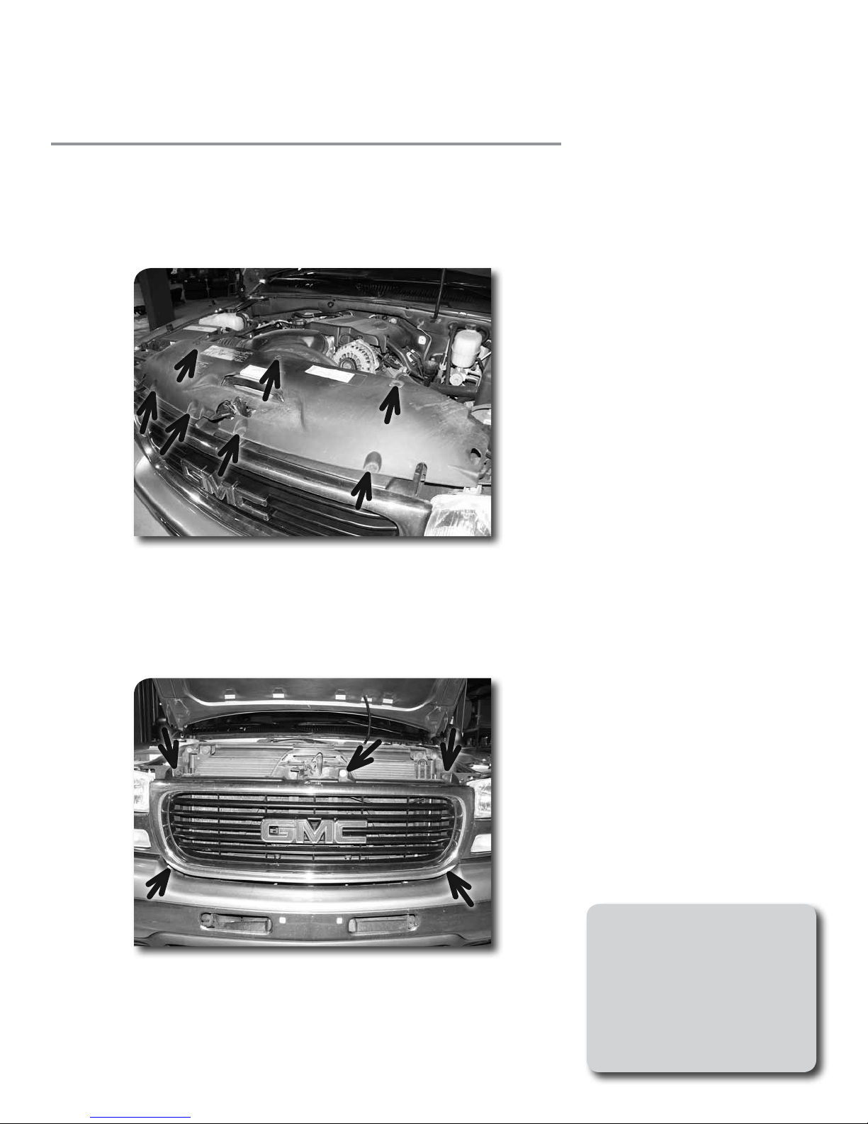
19. Check for any other wires, hoses, cables, etc that may not have enough slack for
1.5” of body lift. Disconnect or reroute these parts as necessary.
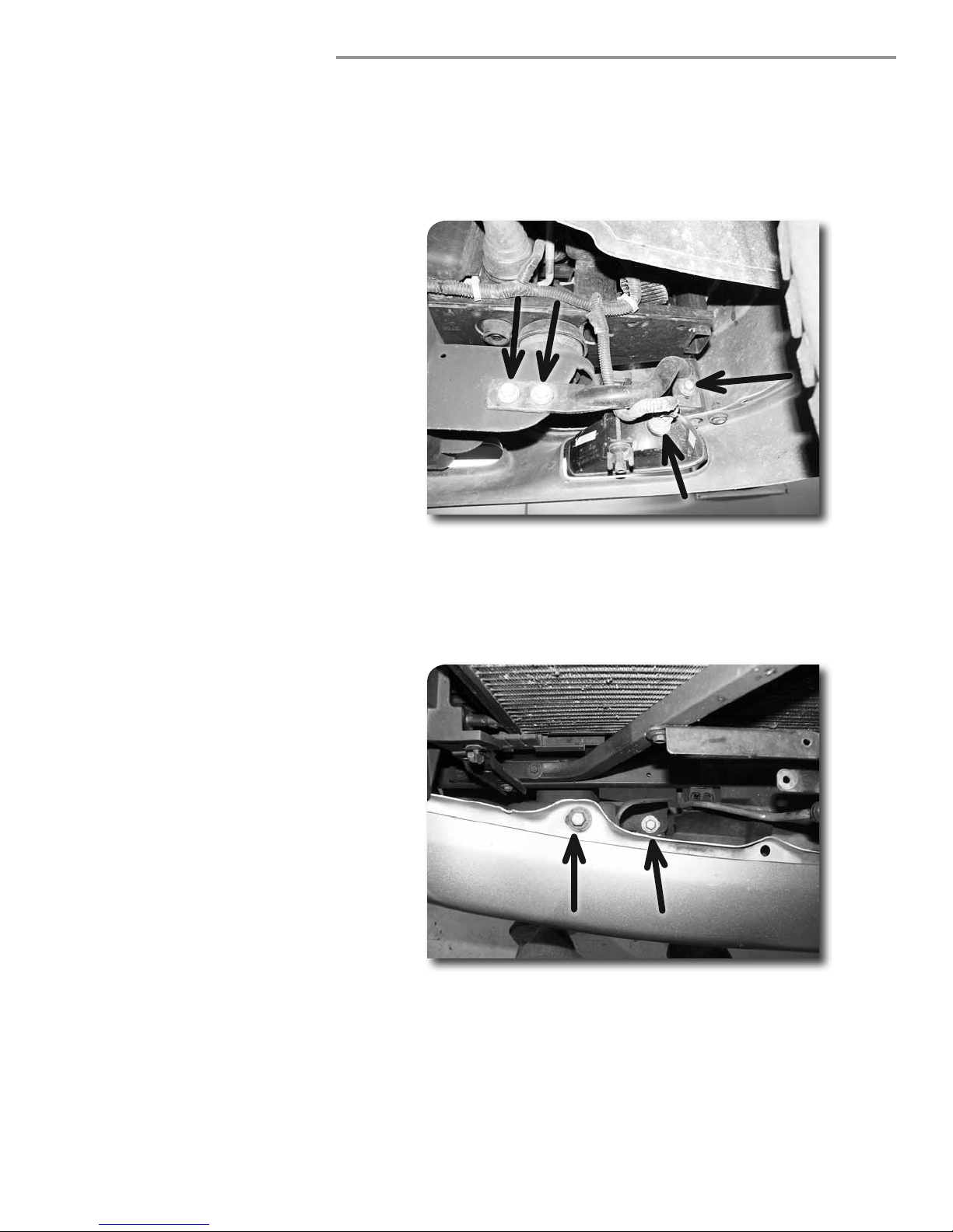
20. Loosen but do not remove all cab mount bolts. All mounting bolts thread up into
the cab except the two front bolts which are mounted downward. The front bolts
are accessed through a hole in the body.
21. Remove the passenger’s side body bolts. Place a hydraulic jack (with wooden
block) under the passenger’s side so that the weight is evenly distributed on the
jack. Slowly raise body, checking for any wires or hoses that may be binding or
stretching. Lift the body just high enough to install the large 3" diameter body
spacers.
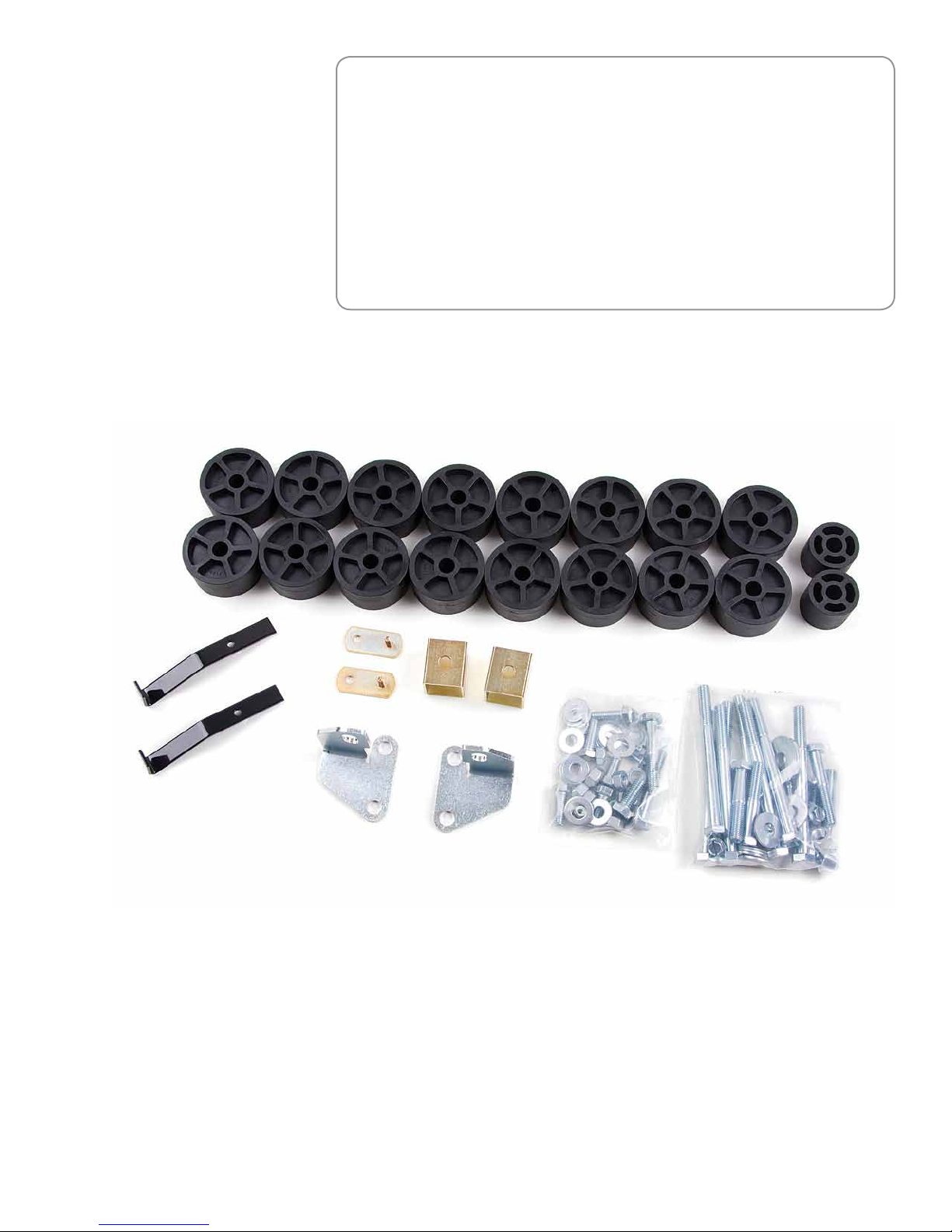
22. Install 12mm x 140mm bolts and 7/16” USS washers in all the body mounts in
combination with the factory body bushing assemblies. The front mount uses the
thick 1-3/4” diameter washers on the bolt that is installed from the top through
the access hole in the body. Fasten the front bolt with a 7/16” USS washers and
12mm nuts along with the factory bushing assemblies. Do not tighten body
mount bolts at this time.
23. Repeat lift procedure for other side of vehicle.
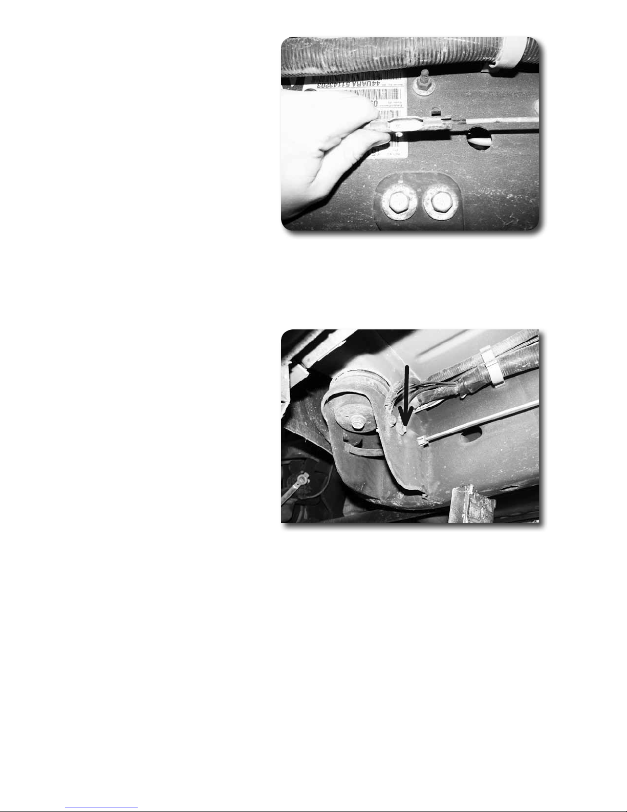
24. Inspect the body to see that it is properly aligned on the frame and the bed.
Remove each body bolt one at a time and apply Loctite to the threads. Torque all
body mount bolts to 65 ft-lbs.
»Bed liFt
25. Loosen but do not remove all bed mounting bolts (six on short bed, eight on
long).
26. Remove the bolts from one side of the bed. Using a hydraulic jack and a block
of wood, lift the bed just high enough to install the body spacers. Install 12mm
x 70mm bolts and 7/16” washers in the body spacers but do not tighten.
27. Repeat the lifting procedure for the other side of the vehicle. Align the bed to the
cab and tighten all mounting hardware. Use Loctite® on all mounting hardware.
28. Remove the rubber pads from the frame where the bed’s cross members origi-
nally rested (four locations on long beds, two on short beds). Place the metal
body spacers at these locations. Figure 15 Attach the spacers to the frame with
5/16" x 3/4” self-tapping bolts. Tighten hardware to 10 ft-lbs.
Step 22 Note
All body mount hardware is lo-
cated in hardware pack #273.
Step 24 Note
If the vehicle is equipped with
aftermarket step bars that mount
off of the body mounts, longer
mounting bolts may be required in
those locations.
Step 26 Note
All bed mounting hardware is
located in hardware pack #273.
Step 28 Note
5/16" bed spacer hardware is
located in hardware pack #273. It
may be helpful to use the bolts to
tap the holes before installing the
spacer.

C9154 Installation - pg. 10
Figure 15
»Front/Under Hood
29. Reconnect the upper and lower steering shaft halves. Align the mark made dur-
ing disassembly. Fasten with the factory bolt and torque hardware to 40 ft-lbs.
30. Reattach the ground wire to the stud on the rewall. Fasten with the original nut
and torque to 10 ft-lbs.
31. Install the new 1.25” fan shroud relocation brackets (w/1/4" studs) to the origi-
nal shroud mounting holes using the stock bolts Figure 16. Install the brackets so
the studs point toward the engine compartment. Torque hardware to 10 ft-lbs.
Figure 16
32. Mount the fan shroud on the relocation bracket studs and fasten with the
provided 1/4” nuts and washers. Torque to 5 ft-lbs.
33. Working from the bottom of the fan shroud, pull the wire loom out away from
the fan shroud. Figure 17A Locate the provided lower fan shroud brackets (2) and
position them as shown. Figure 17B The lower horizontal shroud lip should rest
just below the core support and the shroud pulled tight forward. Use the brack-
ets to mark the position of the holes to be drilled.
Step 32,35 Note
Upper and lower fan shroud hard-
ware is located in hardware pack
#272

C9154 Installation - pg. 11
Figure 17A
Figure 17B
34. Drill a 7/32" holes at each of the marks for the lower shroud brackets.
CAU-
TION: Take care to not drill more then 1/2" past the thickness of the core
support material. The radiator is located just above.
35. With the holes drilled, reposition the lower shroud brackets and fasten with the
provided 1/4" x 3/4" self-tapping bolts. Tighten bolts to 10 ft-lbs. Figure 18
Step 34 Note
It may be helpful to remove the
factory front plastic splash guard
in order to get a better angle for
drilling.

C9154 Installation - pg. 12
Figure 18
36. Use the provided zip ties to secure the wire loom to the two new lower shroud
brackets.
37. Double check fan-to-shroud clearance.
38. Reattach the air intake tube to the throttle body and air lter box with the factory
clamps. Tighten clamps securely. If equipped, reattach the radiator hose to the
intake tube.
39. Reattach the transmission oil cooler to the original location on the core support
with the factory bolts. Torque hardware to 10 ft-lbs.
40. Mount the cooler lines back in the plastic retaining clip at the bottom of the core
support. Check that the cooler lines are not rubbing on anything. It may be
necessary to slightly bend them to properly clear the core support and/or the fan
shroud.
41. Reconnect any other lines, hoses, etc that were removed prior to lifting that were
not outlined in the instructions.
»Front BUmper
42. If equipped, remove the factory tow hooks. Save hardware and hooks. Note
what side each tow hook goes. Figure 19
43. The factory front bumper frame mounts need to be modied. Draw a cut line
that starts on the inside edge of the upper mount tab and runs down along the
inside surface of the frame rail. Figure 20A
Front Bumper
All front bumper hardware is located
in hardware pack #272.

C9154 Installation - pg. 13
Figure 19
Figure 20A
44. Cut the inside of the frame brackets off along the cut line with a reciprocating
saw. Figure 20B
Figure 20B

C9154 Installation - pg. 14
45. Make a second cut line along to remove the front 'bumper' protruding from the
face of the bracket. Figure 20C. Cut the 'bumper' off with a reciprocating saw.
Paint any exposed metal.
Figure 20C
46. Locate the new front bumper brackets. They are driver's and passenger's side
specic. The straight edge/holes go toward the front and the tab points inward.
Line the lower mounting hole of the new bracket with the factory tow hook hole
(hole will be there regardless if the vehicle has tow hooks or not). Also, align
the front vertical edge of the new bracket with the front face of the factory
bracket. Mark the second bracket mounting hole to be drilled. Drill 1/2" hole at
mark. Figure 21
Figure 21 - Pass Side Shown
47. Attach the new brackets to the frame with the provided 7/16" x 1-1/4" bolts, nuts
and washers. Align the lower hole to the existing frame hole and torque upper
hardware to 45 ft-lbs. Figure 22A Reinstall the tow hooks on the correct side and
fasten through the frame and new bracket with the original hardware. Figure 22B
Torque tow hook bolts to 55 ft-lbs.
Step 46 Note
2wd models have a factory bumper
mount that bolts the frame. The new
brackets will bolt to the frame with the
factory bumper bracket bolt. No drill-
ing is necessary.
Step 47 Note
If the vehicle was not equipped
with tow hooks from the factory,
use the second set of 7/16" x 1-1/4"
bolts, nuts and washers provided in
hardware pack #272 for the lower
mounting hole.

C9154 Installation - pg. 15
Figure 22A
Figure 22B
48. Locate the original outside bumper support bracket mount holes on each front
body mount. Measure straight up from the center of the holes 1-1/2" and mark.
Drill 7/16" holes at the marks (4 total). Figure 23 The brackets will be attached
after the bumper is in place.
Figure 23

C9154 Installation - pg. 16
49. Locate the provided 2" diameter x 1-1/2" tall bumper spacers. Slide the bumper
in place over the frame rails and place the spacers between the upper bumper
mount tab and upper frame mount. Align the mounting holes in the bumper,
frame and spacer. Loosely fasten with the provided 12mm x 70mm bolts and
1/2" washers. Figure 24
50. Attach the factory lower bumper tab to the bottom of the new frame brackets
with the provided 1/2" x 1-1/4" bolts, nuts and washers. Leave hardware loose.
Figure 24
51. Loosely fasten the original outer support bracket to the new holes in the front
body mounts with the factory bolts along with the 10mm nuts and 3/8" USS at
washers. Figure 25 Also, attach the supports to the original location on the bum-
per with the factory hardware. Leave all hardware loose.
Figure 25
52. Adjust the bumper to the proper location and torque all mounting hardware.
Tighten the outer support bolts (6 total) to 45 ft-lbs and upper/lower main frame
mount bolts to 60 ft-lbs.
Step 49 Note
The new lower bumper brackets
must be below the lower mount
tabs on the frame.

C9154 Installation - pg. 17
53. Check tow hook clearance to the front bumper valance. They should rest just
above the bottom of the factory cut-out in the valance. Clearance varies between
mount years. Additional valance trimming may be needed.
54. If equipped, reconnect the fog lights in the front bumper.
55. Install the grill on the vehicle in the reverse of how it was removed.
56. Install the plastic core support cover on the top of the core support and fasten
with the original plastic retaining clips.
»parking Brake caBle
57. Locate the tab on the driver's side body mount where the parking brake cable
runs through it. Figure 26A Bend the tab up at against the mount to gain slack
for the cable. Figure 26B Run the cable back through the mount into its original
location. Figure 26C
Figure 26A
Figure 26B

Figure 26C
58. Pull slack on the parking brake cable and clamp it off like it was during disas-
sembly. Reconnect the front cable to the rear cable and remove the clamp.
»FUel line - manUal SHiFt tranSFer caSe only
59. Check the fuel lines near the transfer case shift linkage. They are the on the
driver's side of the transfer case. Be sure that the lines do not interfere with the
shift operation through the full gear selection range. It may be necessary to bend
the fuel lines slightly for proper clearance.
»poSt-inStallation
60. Reconnect battery.
61. Check all hardware for proper torque.
62. Check hardware after 500 miles.
63. Adjust headlights.
Post-Installation
Warnings
1. Check all fasteners for
proper torque. Check to ensure
for adequate clearance between
all rotating, mobile, xed, and
heated members. Verify clearance
between exhaust and brake lines,
fuel lines, fuel tank, oor boards
and wiring harness. Check steering
gear for clearance. Test and inspect
brake system.
2. Perform steering sweep to
ensure front brake hoses have ade-
quate slack and do not contact any
rotating, mobile or heated mem-
bers. Inspect rear brake hoses at
full extension for adequate slack.
Failure to perform hose check/
replacement may result in compo-
nent failure. Longer replacement
hoses, if needed can be purchased
from a local parts supplier.
3. Perform head light check and
adjustment.
4. Re-torque all fasteners after
100 miles. Always inspect fasten-
ers and components during routine
servicing.
Shop for other Performance Lift Kits on our website.
Table of contents
Other Zone Automobile Accessories manuals
Popular Automobile Accessories manuals by other brands

Feniex
Feniex FUSION-S 100 instruction manual

Directed
Directed Directechs DB3 installation guide

Prime Design
Prime Design VBB-226 Assembly instructions

Virtual Reality
Virtual Reality Hands-Free Bluetooth Car Kitpdf VRBT120P installation manual

Cartft
Cartft FleetPC-5-B user manual

Steinhof
Steinhof K-034 FITTING AND OPERATION MANUAL