Zontes ZT310-V1 EURO V User manual

2021/1/13
Service manual
ZT310-V1(EURO V)

Page 1,Total 109 pages
Page
0
Table of Contents …………………………………………………………………………………………………………………………………………………………………………………………
1
1Frame component
1.1
Electrical Device component-1 ……………………………………………………………………………………………………………………………………………………………………………
8
Main harness, dump switch, relay, flasher, rectifier, ignition coil
1.2
Electrical Device component-2 ……………………………………………………………………………………………………………………………………………………………………………
9
Flameout switch, horn, wake-up switch
1.3
Frame plastic parts…………………………………………………………………………………………………………………………………………………………………………………………
10
Set clamp, side cover round glue, fuel tank liner limit glue
1.4
Directional Column component……………………………………………………………………………………………………………………………………………………………………………
11
Lower plate component
1.5
Frame, side bracket, put on the oil operation………………………………………………………………………………………………………………………………………………………………
12
Side bracket,frame oil drain bolt component
;
Muffler connection plate
1.6
PKEcomponent
(
Bosch/colloid battery
)
…………………………………………………………………………………………………………………………………………………………………
13
2Frame & engine combination
2.1
Engine decorative cover components………………………………………………………………………………………………………………………………………………………………………
14
Engine left rear cover,right cover decorative
2.2
Frame & Engine Combination1……………………………………………………………………………………………………………………………………………………………………………
15
Disassemble the rear shock absorber rod plate and pipeline
2.3
Frame & Engine Combination 2.……………………………………………………………………………………………………………………………………………………………………………
16
Hanging piece, bracket component
,
Lower shroud bracket
3Intake system components
3.1
Intake system components (Delphi EFI)……………………………………………………………………………………………………………………………………………………………………
17
Throttle valve body component, air filter, oil pipe
3.2
Carbon canister component.…………………………………………………………………………………………………………………………………………………………………………………
18
Carbon canister, canister solenoid valve
3.3
Air filter filter maintenance …………………………………………………………………………………………………………………………………………………………………………………
19
3.4
Replace the air filter element 1………………………………………………………………………………………………………………………………………………………………………………
20
Remove the side cover, connecting rod plate
3.5
Replace the air filter element 2………………………………………………………………………………………………………………………………………………………………………………
21
Demolition filter external related parts
Contents
Table of Contents

Page 2,Total 109 pages
Page
Contents
Table of Contents
3.6
Replace the air filter element 3………………………………………………………………………………………………………………………………………………………………………………
22
Remove filter bottom case
3.7
Replace air filter element 4…………………………………………………………………………………………………………………………………………………………………………………
23
Replace the air filter
4Rear wheel and rear fork component
4.1
Adjustment chain……………………………………………………………………………………………………………………………………………………………………………………………
24
4.2 Sprocket guard……………………………………………………………………………………………………………………………………………………………………………………………… 25
Removing the sprocket guard
4.3
Sprocket assembly 1…………………………………………………………………………………………………………………………………………………………………………………………
26
4.4
Sprocket assembly 2…………………………………………………………………………………………………………………………………………………………………………………………
27
Disassemble the sprocket assembly
4.5
Rear wheel component 1……………………………………………………………………………………………………………………………………………………………………………………
28
Decomposed rear rim component
4.6
Rear wheel component 2……………………………………………………………………………………………………………………………………………………………………………………
29
Demolition of rear wheel bearing, rear disc brake disc, rear sub-mud assembly
4.7
Rear sub-slab assembly 1……………………………………………………………………………………………………………………………………………………………………………………
30
Vice fender extension cable
4.8
Rear auxiliary mud plate assembly 2………………………………………………………………………………………………………………………………………………………………………
31
Disassembled rear mud plate bracket assembly
4.9
Rear auxiliary mud plate assembly 3………………………………………………………………………………………………………………………………………………………………………
32
Disassembled rear mud plate bracket assembly
4.10
Rear turn signal after sale parts………………………………………………………………………………………………………………………………………………………………………………
33
Rear left and right turn signals and rear license plate lights for sale
4.11
Chain adjuster assembly……………………………………………………………………………………………………………………………………………………………………………………
34
Disassemble chain adjuster and maintain
4.12
Rear mud board………………………………………………………………………………………………………………………………………………………………………………………………
35
4.13
Rear shock absorption………………………………………………………………………………………………………………………………………………………………………………………
36
Demolition after shock absorption, rear shock absorption adjustment
4.14
Rear shock absorber rod assembly 1…………………………………………………………………………………………………………………………………………………………………………
37
Remove the rear flat fork connecting rod, rear shock absorber rod assembly
4.15
Rear shock absorber rod assembly 2…………………………………………………………………………………………………………………………………………………………………………
38
Disassemble shock absorber connecting rod assembly
4.16
Rear fork component………………………………………………………………………………………………………………………………………………………………………………………
39

Page 3,Total 109 pages
Page
Contents
Table of Contents
Decomposed flat fork component
4.17
Replace the rear brake pads…………………………………………………………………………………………………………………………………………………………………………………
40
4.18
Rear brake main pump adds brake fluid……………………………………………………………………………………………………………………………………………………………………
41
5Pedal component
5.1
Pedal height adjustment……………………………………………………………………………………………………………………………………………………………………………………
42
Shift lever, brake pedal height adjustment
5.2
Front right pedal mounting position adjustment 1…………………………………………………………………………………………………………………………………………………………
43
5.3
Front right pedal mounting position adjustment 3…………………………………………………………………………………………………………………………………………………………
44
5.4
Front left pedal mounting position adjustment………………………………………………………………………………………………………………………………………………………………
45
5.5
Front right footrest component-3……………………………………………………………………………………………………………………………………………………………………………
46
Decompose the Front right pedal component
5.6
Shift lever assembly…………………………………………………………………………………………………………………………………………………………………………………………
47
5.7
Front left footrest component-3………………………………………………………………………………………………………………………………………………………………………………
48
Decompose the front left footrest component
5.8
Rear pedal assembly…………………………………………………………………………………………………………………………………………………………………………………………
49
5.9
Rear right pedal bracket components………………………………………………………………………………………………………………………………………………………………………
50
5.10
Rear left pedal bracket components…………………………………………………………………………………………………………………………………………………………………………
51
6Cooling system component
6.1
Change the oil………………………………………………………………………………………………………………………………………………………………………………………………
52
6.2
Replace the oil filter…………………………………………………………………………………………………………………………………………………………………………………………
53
6.3
Add coolant…………………………………………………………………………………………………………………………………………………………………………………………………
54
6.4
Radiator covercomponent 1…………………………………………………………………………………………………………………………………………………………………………………
55
Disassemble the radiator covercomponent
6.5
Radiator covercomponent 2…………………………………………………………………………………………………………………………………………………………………………………
56
6.6
Vice water tank components…………………………………………………………………………………………………………………………………………………………………………………
57
6.7
Radiator tubing component…………………………………………………………………………………………………………………………………………………………………………………
58
Disassemble the radiator tubing component
6.8
Cooling liquid………………………………………………………………………………………………………………………………………………………………………………………………
59
Remove the shroud component and release the coolant
6.9
Main tank component 1……………………………………………………………………………………………………………………………………………………………………………………
60
6.10
Main tank component 2……………………………………………………………………………………………………………………………………………………………………………………
61
Disassemble the main tank component

Page 4 ,Total 109 pages
Page
Contents
Table of Contents
7Front fork component
7.1
Throttle/clutch cable clearance adjustment…………………………………………………………………………………………………………………………………………………………………
62
Adjust the throttle line, clutch cable free travel
7.2
Light height adjustment……………………………………………………………………………………………………………………………………………………………………………………
63
7.3
Replacement clutch cable……………………………………………………………………………………………………………………………………………………………………………………
64
7.4
Replace the throttle line………………………………………………………………………………………………………………………………………………………………………………………
65
7.5
Steering adjustment…………………………………………………………………………………………………………………………………………………………………………………………
66
Adjustment steering device
7.6
Add brake fluid, rocker adjustment…………………………………………………………………………………………………………………………………………………………………………
67
Add brake fluid, brake rocker adjustment
7.7
Replace the front brake pads,front brake caliper mounting plate……………………………………………………………………………………………………………………………………………
68
7.8
Front wheel component………………………………………………………………………………………………………………………………………………………………………………………
69
Disassemble the front wheel, front disc brake disc, front axle component
7.9
Front mud board & wheel speed sensor component…………………………………………………………………………………………………………………………………………………………
70
Decompose front wheel speed sensor component, front mud plate component
7.10
Headlights assembly 1………………………………………………………………………………………………………………………………………………………………………………………
71
Headlights assembly, cable plug
7.11
Headlights assembly 2………………………………………………………………………………………………………………………………………………………………………………………
72
Remove headlights
7.12
Headlights assembly 3………………………………………………………………………………………………………………………………………………………………………………………
73
Remove headlights upper bracket, front turning signal
7.13
Right hand component………………………………………………………………………………………………………………………………………………………………………………………
74
Remove right rear view mirror, right hand rubber sleeve, balance block
,
Replace the front brake switch
7.14
Left hand component………………………………………………………………………………………………………………………………………………………………………………………
75
Demolition handle, clamp, instrument component
7.15
Directional lever
、
TFT Instrument…………………………………………………………………………………………………………………………………………………………………………
76
Demolition handle, clamp, TFT instrument component
7.16
Front shock absorber, upper plate component………………………………………………………………………………………………………………………………………………………………
77
Front shock absorber, faucet lock, upper plate component
7.17
Uplink plate, direction handle block component……………………………………………………………………………………………………………………………………………………………
78
Disassemble the block, the upper plate
7.18
ABS brake system-1…………………………………………………………………………………………………………………………………………………………………………………………
79
Remove the control unit protection cover, releasing brake fluid, hydraulic control unit

Page 5,Total 109 pages
Page
Contents
Table of Contents
7.19
ABS brake system-2…………………………………………………………………………………………………………………………………………………………………………………………
80
Remove the front disc brake main pump and oil pipe
7.20
ABS brake system-3…………………………………………………………………………………………………………………………………………………………………………………………
81
Remove the front disc brake caliper and tubing
7.21
ABS brake system-4…………………………………………………………………………………………………………………………………………………………………………………………
82
Disassemble the disc brake main pump and tubing
7.22
ABS brake system-5…………………………………………………………………………………………………………………………………………………………………………………………
83
Disassemble rear disc brake calipers and tubing, wheel speed sensor
8Fuel tank cover component
8.1
Fuel tank cover component…………………………………………………………………………………………………………………………………………………………………………………
84
Disassemble the fuel tank cover component
8.2
Tank middle cover component………………………………………………………………………………………………………………………………………………………………………………
85
Decompose the fuel tank cover, fuel tank cover, fuel tank lock
8.3
Fuel tank outer cover components……………………………………………………………………………………………………………………………………………………………………………
86
Disassemble the fuel tank outer cover ,rotating bracket
8.4
Fuel pump……………………………………………………………………………………………………………………………………………………………………………………………………
87
Disassemble the fuel pump, fuel tank buffer rubber
8.5
Fuel tank front decorative cover……………………………………………………………………………………………………………………………………………………………………………
88
Disassemble the fuel tank front decorative cover,USB charging cable
8.6
Fuel tank decorative cover lower part………………………………………………………………………………………………………………………………………………………………………
89
8.7
Fuel tank decorative cover components 1……………………………………………………………………………………………………………………………………………………………………
90
8.8
Fuel tank decorative cover components 2……………………………………………………………………………………………………………………………………………………………………
91
9Side cover component
9.1
Side cover component………………………………………………………………………………………………………………………………………………………………………………………
92
Decomposition side cover component
10 Guard bar sembly
10.1
Guard bar assembly 1………………………………………………………………………………………………………………………………………………………………………………………
93
Disassemble the guard bar outer parts
10.2
Guard bar assembly 2………………………………………………………………………………………………………………………………………………………………………………………
94
Disassemble left and right guard components
10.3
Guard bar assembly 3………………………………………………………………………………………………………………………………………………………………………………………
95

Page 6 ,Total 109 pages
Page
Contents
Table of Contents
Disassemble the left and right guard bar components
10.4
Engine decorative cover components………………………………………………………………………………………………………………………………………………………………………
96
Disassemble the engine decorative cover
11 REAR COVER COMPONENT
11.1
Electrical device box component (colloid battery)…………………………………………………………………………………………………………………………………………………………
97
11.2
Backrest assembly component………………………………………………………………………………………………………………………………………………………………………………
98
Disassemble the backrest,Backrest rubber
11.3
Tail skirt taillight component 1………………………………………………………………………………………………………………………………………………………………………………
99
Disassemble PKE single antenna, buzzer
11.4
Tail skirt taillight component 2………………………………………………………………………………………………………………………………………………………………………………
100
Disassemble the tail skrit left and right decorative cover,decorative cover bracket
11.5
Tail skirt taillight component 3………………………………………………………………………………………………………………………………………………………………………………
101
Disassemble the rear aluminum alloy bracket
11.6
Tail skirt taillight component 4………………………………………………………………………………………………………………………………………………………………………………
102
Rear skirt taillight component
12 Cushion component
12.1
Cushion………………………………………………………………………………………………………………………………………………………………………………………………………
103
Discomponent and component cushion; seat cushion rubber separately purchased parts
13 Muffler component
13.1
Oxygen sensor………………………………………………………………………………………………………………………………………………………………………………………………
104
13.1
Muffler component 1………………………………………………………………………………………………………………………………………………………………………………………
105
Disassemble the muffler peripheral components
13.2
Muffler component 2………………………………………………………………………………………………………………………………………………………………………………………
106
Disassemble the muffler components
13.3
Muffler component 3………………………………………………………………………………………………………………………………………………………………………………………
107
Disassemble the muffler decorative cover
14 Lower shroud component
14.1
Lower shroud component-1…………………………………………………………………………………………………………………………………………………………………………………
108
Remove the shroud component, shroud bracket
14.2
Lower shroud component-2…………………………………………………………………………………………………………………………………………………………………………………
109

Page 7,Total 109 pages
Page
Contents
Table of Contents
Decompose the lower shroud component
©Guangdong Tayo Motorcycle Technolog Co.
Ltd All rights reserve
All the information, illustrations and photographs collected inthis manual are compiled according tothe latest products. However, there may be some inconsistencies between your motorcycle
and this manual due to the continuousimprovement of the product and other changesFor colors or upgrades, please refer to the part codes on the official website. This manual will not be listed
in detail; Ifthe part names inthis manual are inconsistent with the official website, the official website shall prevail. This manual iscompiled onthe basis ofthe chinese version ofZT310-V1
version. The export version is different from the chinese version with only a few parts, such as decals, ECU version, muffler catalyst, etc. Although the status of such parts are different, the
disassembly method issame, sorefer tothe chinese manual.

1
、
FRAME COMPONENT
8
CHK
ADJ
NO. PART NO.
PART NAME QTY CAUTION
1 1184200-169000 ZT310-V wiring harness assembly (Bosch) 1
2 1224100-030000 Plug cable tie (black 4.8×130) 2
3 1224100-037000 0 level antiflaming binding
(
black 3.6×295
)
9
4 1184100-017000 ZT250
-
S Electronic fuel injection relay 5 KH-1A4T
5 1244100-082000 ZT250
-
R Dump switch rabber 1
6 1184100-002000 ZT250
-
S Dump switch 1
7 1184200-039000 ZT310
-
R Flasher 1
8 1251100-101000 Non-standard bolt M6×12
(
304 stainless steel
)
5
9 1224200-205000 ZT310 electronic cushion lock guide block 1
10 1274100-058000 ZT310 seat lock 1
11 1184100-010000 ZT250
-
S starting relay 1
12 1251100-102000 Non-standard bolt M6×16
(
304 stainless steel
)
1
13 1274200-171000 ZT310-V relay bracket 1
14 1251300-085093 Non-standard cap nut M6 (environmental color) 2
15 MSE6.0 Controller-ZT180MN 1
【
1
】
16 1274200-268000 ZT310
-
VX Bosch ECU bracket 1
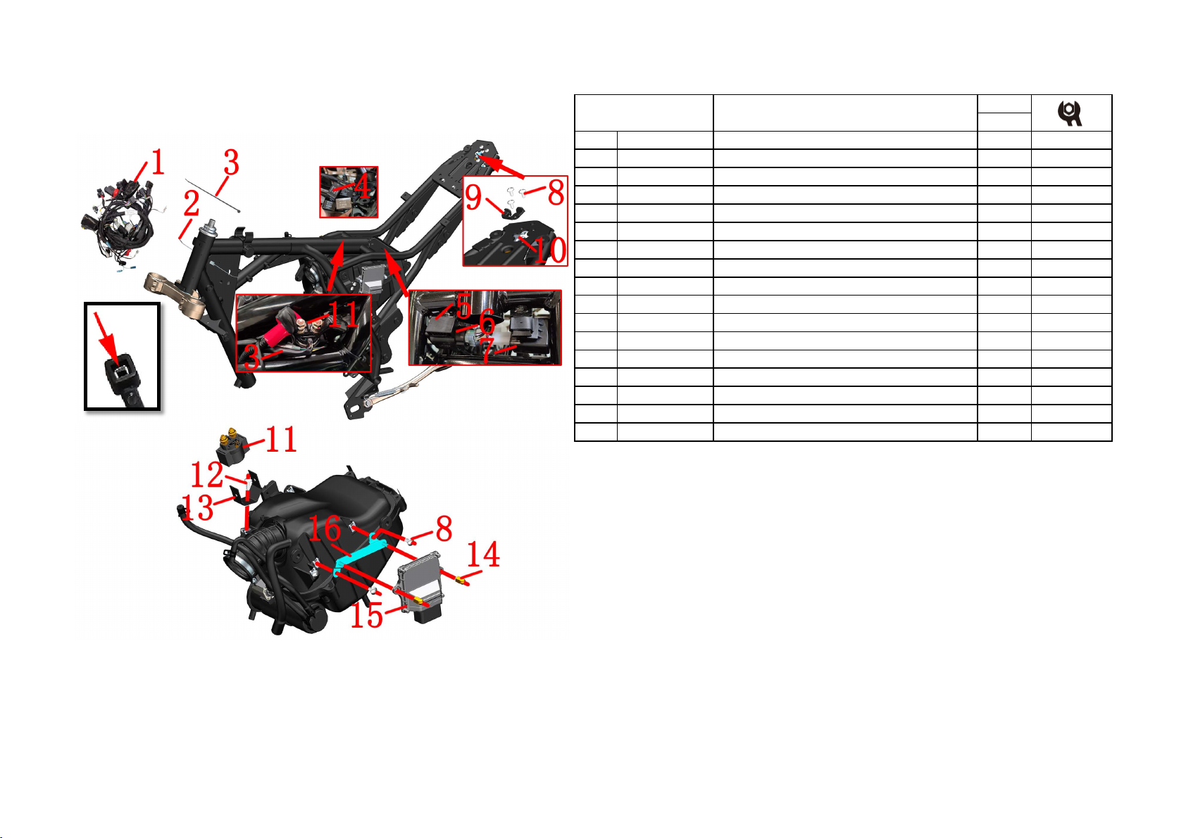
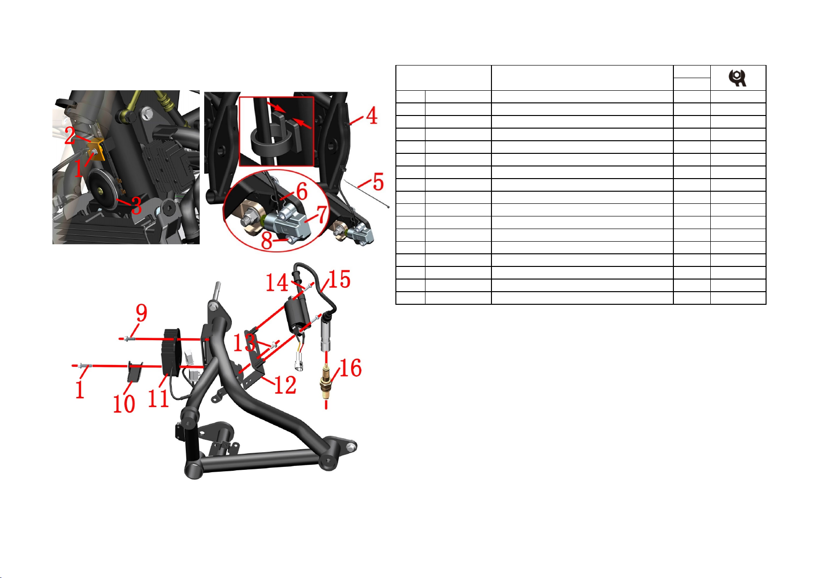
Fig.1 FRAME&ELECTRONIC
PARTS COMPONENT Electronic parts COMPONENT-1
CAUTION
:
●Please notice the limit of the bracket when dismantling flasher and dump switch sleeve, beware of
hurting your fingers.
●【1】If the part code is empty, it indicates that the part has multiple states or colors. For specific
states, please find the corresponding state or color in the official website parts. Only the disassembly and
assembly steps are explained here, and the color and status do not affect the disassembly and assembly
process. This description will not be added if there is such a situation later in this manual.
PROCEDURE:
●Flasher and dump switch
Remove the rubber sleeve ⑺that connects the flasher ⑹to the mounting bracket on the frame, and remove the
dump switch with the same method, then separate the dump switch ⑸.
●Relay and ECU
Locate the main harness rubber sleeve on the right side of the frame, pull out the EFI relay ⑷. Locate the
starter relay ⑾above the air filter to remove the sheath of the harness and remove the self-contained nut to
remove the relay from the relay bracket ⒀. Using 4# inner hexagon socket disassemble the bracket ⒀after
removing the bolt ⑿。Pull out the plug of the engine controller ⒂on the left side and use a 10# sleeve to
remove the nut ⒁. Remove the 2 bolts ⑻with 4# hexagon socket and then take off the ECU bracket ⒃.
●Seat lock
Take off the plug of the seat lock , and cut off binding ⑶. Use a 4# inner hexagon to remove the front bolt ⑻,
and remove the guide block ⑼; remove the 2 rear bolts and remove the electronic cushion lock ⑽.
●Main harness
Different plug-in methods are different, please unplug all the electrical components connected to the main
thread according to the actual operation. It needs to use a word screwdriver, forceps, scissors and other tools to
assist.The binding ⑶can be picked out by using scissors.
The plug strap ⑵is a non-detachable structure and it is not recommended to cut it directly. It is difficult to
remove the broken portion of the buckle that is forcibly removed from the frame triangular reinforcing plate.

1
、
FRAME COMPONENT
9
CHK
ADJ
NO. PART NO.
PART NAME QTY CAUTION
1 1251100-061093 M6×22 Screw bolt 2
2 1274200-033000 ZT310
-
R No.2 holder of front disc oil pipe 1
3 1184200-004000 ZT310 Horn 1
4 1274100-017000 ZT250
-
S Cable clip 2
5 1224100-037000 0 level antiflaming binding
(
black 3.6×295
)
2
6 1274100-095000 ZT250
-
S Holder of flameout switch cable 1
7 1184100-012000 ZT250
-
S Flameout switch 1
8 1250205-040095 GB70.1M8×16 Screw 2
9 1251112-001093 M6×16 Hexagon flange bolts (color zinc) 1
10 1274200-183000 ZT310-V outlet pipe bracket 1
11 1184200-174000 ZT310 rectifier (five wire) 1
12 1274200-141000 ZT310-V high voltage package bracket 1
13 1251100-101000 Non-standard bolt M6×12
(
304 stainless steel
)
1
14 1184200-177000 ZT310 EFI ignition coil 1
15 1250201-032093 GB818M5×16 bolt 2
16 1050954-017000 LDK8RTIP
-
0.8 sparking plug 1
Fig.2 FRAME&ELECTRONIC
PARTS COMPONENT Electronic parts COMPONENT-2
PROCEDURE:
●Horn
Take off the plug of horn take the horn ⑶by one hand, using 8# plum wrench rotate the screw ⑴by another
hand remove the holder ⑵then take off the horn.
●Flameout switch
Find and take off the plug of the flameout swich ⑹press and take off the cable clip ⑷cut ribbon ⑸.Using
the 6# inner hexagon tool, remove the bolts ⑻、the holder ⑹and the flameout switch ⑺.
●Rectifier
Find and remove the rectifier plug, Using 8# sleeve remove the bolt ⑴,remove the outlet pipe bracket⑽;
Using 8#sleeve remove the bolt ⑼and remove the rectifier ⑾.
●Ignition coil
Pull out the metal shield cap ofthe ignition coil ⒂from the spark plug ⒃on the engine, Then remove the bolt
⒁with a Phillips screwdriver to remove the coil ⒂.Using 4# inner hexagon socket remove the bolt ⒀and
remove the high pressure package bracket ⑿.
CAUTION:
●Do not pull the cable hard when removing the sub-mud switch.

1
、
FRAME COMPONENT
10
CHK
ADJ
NO. PART NO.
PART NAME QTY CAUTION
1 1224100-030000 Plug strap (black 4.8×130) 2
2 1244100-019000 ZT250
-
S Inner fuel tank fix glue cushion 1
3 1244100-002000 ZT250
-
S side cover cushion 6
4 1240300-007000 HJ125
-
6 battery cushion 1
5 1244100-061000 ZT250 Frame water proof rubber plug 2
6 1250201-030093 GB818M5×12 (color zinc) 2
7 1240300-060000 KD150
-
E Wear block 1
PROCEDURE:
●Inner fuel tank ficx glue cushion
Use both hands to hold the two ends cylinder parts of the inner fuel tank limited glue cushion ⑵and should
push it out.
●Side cover cushion
Remove the side cover cushion ⑶with your hand directly.
●Battery cushion
Put off the battery cushion ⑷directly by hand.
●Frame waterproof rubber plug
Remove the frame waterproof rubber plug ⑸with your hand directly.
●Wear block
Use a Phillips screwdriver to remove the 2 bolts ⑹and then remove the wear block ⑺.
CAUTION:
●It must be dismantled them first, such as the cushion, fuel tank cover, inner fuel tank, sider cover, tail dress
and so on.
●All parts should be correctly assembled.
●The plug strap ⑴is a non-detachable structure and it is not recommended to cut it directly. It is difficult to
remove the broken portion of the buckle that is forcibly removed from the frame triangular reinforcing plate.
Fig.3 FRAME&ELECTRONIC
PARTS COMPONENT Frame plastic parts

1
、
FRAME COMPONENT
11
CHK
ADJ
NO. PART NO.
PART NAME QTY CAUTION
1 1134100-007000
ZT250
-
S Rating nut lock washer 1
2
1251300-046093 ZT250
-
S Steering column rating nut (color zinc) 2
3 1244100-015000
ZT250
-
S Rating nut glue cushion 1
4
1224100-005000 ZT250
-
S Steering column upper dustproof cover 1
5
1130900-024000 ZT250
-
S Blowout patch 2
6
1130900-022000 ZT250
-
S One-piece steel ball 2
8
1224100-006000 ZT250
-
S Steering column down dustproof cover 1
【
1
】
Fig.4 FRAME&ELECTRONIC
PARTS COMPONENT
Steering rack component
PROCEDURE:
●Dissembly
Remove the lock washer ⑴.
Remove the top adjusting nut ⑵by using a special four-jaw or hook wrench tools.
Remove the rubber pad ⑶.
With one hand to hold down the down connected plate assembly ⑺, the other hand use a special four-
jaw set or hook wrench to remove the adjusting nut ⑵.
Remove the upper dustproof cover ⑷.Remove the down connected plate component ⑺.
Remove the axletee ring ⑸of the upper riser and the steel ball ⑹.
Remove the down connected plate component ⑺.
Remove the steel ball of the down connected plate component ⑺.
●Assemble
When reassembling, the conjoined steel beads should be painted lubricating grease,attention to the
dosage.
The torque of rating nut which closes to upper dustproof cover is required to about 14N.m.so as to be
able to rotate out of nimbleness.
The top adjusting nut only needs to rotate to the bottom of the nut groove alignment, not too tight to
prevent the rubber pad ⑶from deformation too larg.
ZT250-S Down connected plate (selfmade/with
blowout patch) component
CAUTION:
●Remove the head part component, handlebarcomponent and front shock absorber component first.
●Please pay attentin to fix the awaiting repair motorcycles during disassembly,prevent dumping by accident.
●
Please check whether the steel beads of the conjoined body have abnormal phenomena such as partial abrasion
and rust.If YES, please buy the regular accessories on ZONTES official website, if not, please be sure to grease
the old grease and repaint the lubricating grease on it.
●It must be to check whether the steel ball is available during reassembly.
●It must be reasonable to adjust the steering, too loose will cause the locomotive to brake slightly, and the
locomotive will shake slightly, too tight can lead to inflexibility, resulting in safety hazards.
●If you have the ability and the right tool, you can change the shaft ring ⑸and the dustproof cover ⑻.During
the replacement process, pay attention to the protection of the lower connected plate. After replacement, it must
be to check the parallelism of the column and the damping hole, the vertical degree of the vertical column and the
lower connected plate.
●【1】the down connected plate (selfmade/with blowout patch) component ⑺, has been contains the Steering
column down dustproof cover ⑻.
7 1134100-015000 1

1
、
FRAME COMPONENT
12
CHK
ADJ
NO. PART NO.
PART NAME QTY CAUTION
1
ZT310-V1 frame assembly 1
2
1130900-026000 ZT250
-
S Fix loop 2after-sale
3
1274100-006000 ZT250
-
S Frame engine oil filter screen 1
4
1051453-003000 27.4×2.65 Acrylate O gule cushion loop 1
5
1274100-024000 ZT250
-
S Oil cooling joint 1 50±4N.m
6
1244100-033000 Sealing gasketφ12×φ20×2 1
7
1251100-066093 M12×1.5×15 Ablassschraube
(
color zinc
)
1 24±4N.m
8 1251300-057093
Non-standard bolt M10×1.5
(
dacromet
)
1 45±5N.m
9 1251700-025091
ZT250
-
S Side support bush 1
10
Side bracket 1
11 1251100-088094
Non-standard bol M10×1.5×43
(
dacromet
)
1
12 1264100-001000
ZT250
-
S Side support spring 1
13
1250205-040095 GB70.1 inner hex bolt M8×16(color Zinc) 2
14
1274200-264000 ZT310
-
VX muffler suspension connecting plate 1
15
1274100-068095 ZT310 Muffler flanging bushing 4
16
1241200-045000 KD150
-
U muffler suspension cushioning rubber 2
CAUTION
:
●Remove the wind deflector component, handle bar component, steering column component first.
●Paint the lubricating grease on the cushion ring to decrease the rotary resistance of front forklift.
Fig.5 FRAME&ELECTRONIC
PARTS COMPONENT
Frame, Side support, the operation of releasing engine
oil
PROCEDURE:
●Checking the cushion loop
Checking whether the cushion loop ⑵is frayed, If there is one, it needs to be replaceds. fix the cushion loop
well and paint the lubricating grease on it with appropriate tool.
●Replacing the engine oil filter screen
Put the oil pan on the bottom and use the 21# sleeve to remove the oil cold joint ⑸, O ring ⑷, and oil filter
screen ⑶. When replacing the oil filter screen ⑶, the O-ring ⑷must be replaced at the same time. The oil
cooling joint ⑸must be tightened well when re-assembling which meets the standard torque value.
●Realease the frame tube enging oil
Put the oil pan at the bottom, use the 14#sleeve to remove the oil bolts ⑺and the sealing gasket ⑹, and remove
the oil from the frame tube. Refer to the instructions for detailed steps to replace the oil. It is recommended that
the engine oil should be replaced with oil bolts ⑺and sealing gasket⑹to prevent oil leakage.
●Sider support
Use the cross screwdriver to remove the side support spring, and guard against the personal injury caused by
spring contraction, remove the nuts ⑻and bolts ⑾with the 14#sleeve. Remove the side support ⑽and bush ⑼,
paint the lubricating grease on the bush⑼when re-assembling ,then put it into the frame ⑴.
●Muffler suspension connecting plate
Remove 2 bolts ⒀with 6# inner hexagon, and remove the connecting plate assembly. Remove 4 pieces of
bushing ⒂and 2 pieces of cushion rubber ⒃from connecting plate ⒁.

1
、
FRAME COMPONENT
13
CHK
ADJ
NO. PART NO.
PART NAME QTY CAUTION
1 1224100-010000
ZT250
-
S swell nail 1
2 1244100-061000
ZT250 anti
-
water rubber of frame 1
3 1250105-018091
GB5789 M8×70(white zinc) 1
4 4044201-256051
ZT310
-
V fender ball (dark grey matte) 1
5
Right side cover 1
6 1251100-101000
Non-standard bolt M6×12 (304 stainless steel) 4
7 1184200-137000
ZT310 PKE Controller
(
bracelet edition) 1
8 1274200-271000
ZT310
-
V1 PKE holder 1
9 1244200-132000
ZT310PKE rubber sleeve 1
PROCEDURE:
●Side cover
Remove the seat cushion first, and then remove the expansion nails ⑴at the connection between the right side
cover ⑸and the rear cover. Remove the waterproof rubber plug ⑵, use a T12 sleeve to loosen the bolt ⑶by 10-
15 threads, without completely removing it. Pull out the decorative ball ⑷and rotate it clockwise to stagger the
groove on the right side cover. Pull out the right side cover in the order of a-b-c-d. When assembling, the staples
should be installed in sequence from d-c-b-a; the expansion nails should be installed last.
●PKE Controller
Unplug the PKE plug,use a 4# allen wrench to remove the two bolts ⑹to remove the PKE assembly ⑺and
ZT310PKE rubber sleeve⑼;
●PKE bracket
Use a 4# allen wrench to remove two bolts ⑶to remove the PKE bracket ⑻;
●Fuse
The band version of the PKE assembly uses 2 small 15A fuses.
●Charging
①the charging DC interface; ②the charging fuse; ③the PKE fuse, which must be unplugged when charging
the battery through the DC interface with the charger; ④the TEST button, which functions as the unlock button
on the secondary switch.
CAUTION:
●
When inserting and pulling out the fuse, please pay attention to the vertical alignment before disassembly, and
it is strictly prohibited to bend. A qualified fuse should be used.
●PKE cables need to be protected. Non-professionals are strictly prohibited to disassemble the PKE system
components, otherwise it may cause permanent damage.
●Please refer to the driver's manual for PKE operating instructions.
●Be careful not to overcharge the charging time. Please refer to the manual for details on battery usage and
maintenance.
●The button battery model used in the band version: CR1225.
Fig.6 FRAME&ELECTRONIC
PARTS COMPONENT PKE component(Bosch/colloid battery)

2
、
FRAME & ENGINE COMPONENT
14
CHK
ADJ
NO. PART NO.
PART NAME QTY CAUTION
1 1251100-102000 Non-standard bolt M6×16 (304 stainless steel) 3
2 1274100-018000
ZT250
-
S muffler anti-scald plate bushing 3
3 1244100-017000
ZT250
-
S muffler anti-scald plate rubber 3
4 1224200-157000
ZT310
-
V Trim cover of right engine cover 1
5 1251112-005093 M6×75 hexagon flange bolt ( color zinc) 3 10N.m
6 1274200-221000
ZT310
-
V Mount bracket of engine right trim cover 1
7 1251112-003093 M6×45 hexagon flange face 9.8 bolt (color zinc) 3 10N.m
8 1251112-006093 M6×90 hexagon flange bolt (color zinc) 1 10N.m
9 1274200-220000 Front mount bracket of engine right trim cover 1
10 1274200-041000
ZT310 pipe clamp
(
φ26
)
1
11 1244200-068000
ZT310
-
V Engine water inlet pipe 1
12 Rear left cover of engine 1
13 ZT310-V Muffler Left Anti-scalding Plate 1
14 1251100-135000
Non-standard bolt M10×1.5×95
(
dacromet
)
1
15 1251300-057093
Non-standard nut M10×1.5
(
dacromet
)
1 65±5N.m
PIC.1 FRAME&ENGINE ENGINE TRIM COVER ASSY
PROCEDURE:
●Engine right trim cover assembly
Using 4# inner hexagon socket disassemble 3 bolts ⑴and take out the right trim cover components.Remove the
bushing ⑵、buffer rubber ⑶from the right trim cover components.Using 8# sleeve disassemble the bolts ⑸
and take out the bracket ⑹. Using 8# sleevedisassemble the bolts ⑺、⑻and take out the bracket ⑼.Use a
screwdriver to loosen clamp ⑽, unplug the water inlet pipe ⑾
●Engine left rear cover
Using 8# sleeve remove the bolt ⑺disassemble the rear cover ⑿.
●Anti-scald left muffler plate
Remove the lower shroud assembly first. Secure the head of the bolt ⒁with a 14# sleeve and remove the nut
⒂with a 14# sleeve.Grab the anti-scalding plate ⒀and using 8# sleeve remove the 2 bolts ⑸to remove it.
CAUTION:
●The 3 M6 bolts of the engine trim cover bracket must be coated with thread fastening glue before reassembly,
with a torque of 10N.m.
●The coolant should be drained before disassembly.
●Swallowing or inhaling the coolant can be harmful to the human body.Please thoroughly clean any exposed
skin such as hands, face, etc. after each addition of coolant.Contact poison control center or hospital immediately
if swallowed.If inhaled, please go to a ventilated environment immediately.In case of accidental splash into eyes,
please immediately flush eyes with plenty of running water and seek medical treatment in time.Be sure to stay
away from children and pets.

2
、
FRAME & ENGINE COMPONENT
15
CHK
ADJ
NO. PART NO.
PART NAME QTY CAUTION
1
1250104-006097 GB16674M6×12 (chromed/HH) 4
2 1274100-057095
Flanging bushing φ6.2×φ8.5×3.5
+
φ14×1.5 4
3 1244100-052000 Buffer rubber of flanging bushing (φ8.5×φ14×1) 4
4 1224200-193000 ZT310-VX rear shock absorber connecting rod plate 1
5 1274200-041000 ZT310 Water pipe clamp (φ25) 1
6 1251100-061093 M6×22 Hex flang bolt thread level 8.8 (color zinc) 3
7 1251112-003093 M6×45 Hex flange surface 9.8 bolt (color zinc) 2
8 1154200-021000
ZT310
-
VX clutch cable 1
9 1051354-004000 Φ56×10 clamp components 1
10 1274200-090000 ZT310 water pipe clamp(φ26) 1
11 1184200-177000 ZT310 EFI ignition coil 1
PROCEDURE:
●Connecting rod plate assembly
Use an 8# sleeve to remove 4 bolts ⑴, and remove the bushing ⑵and cushion rubber ⑶. Remove the connecting rod
plate ⑷.
●Pipeline
Refer to the steps for draining coolant and oil to drain the oil inside the engine before proceeding to the next step.
Use an 8# sleeve to remove the 2 bolts ⑹on the right, and remove the bottom oil inlet pipe.
Use a screwdriver to loosen the clamp ⑸, pull out the water pipe, remove the engine oil outlet pipe, and then insert the
water pipe back.
Use an 8# sleeve to remove the 2 bolts ⑺, remove the rear brake main pump assembly, and then reinstall the bolt ⑺.
Refer to the detachment procedure to remove the end of the clutch line ⑻connected to the engine.
After loosening the pipe clamp ⑼, pull out the throttle valve body assembly backward to separate it from the intake
manifold.
Use an 8# sleeve to remove the left bolt ⑹, and remove the oil pipe.
Use the hoop pliers to loosen the hoop ⑽and pull out the end of the water outlet pipe connected to the engine.
Unplug the end of the ignition coil ⑾connected to the spark plug.
●Line
Unplug all wires connected to the engine, such as negative wire, water temperature sensor plug, gear sensor plug, etc.
CAUTION:
●It is necessary to remove the seat cushion, fuel tank, side cover, pedal support, wind deflector, shift lever, muffler,
radiator and pipe, cable, air filter joint, chain, engine negative pole, etc.
●The waste oil needs to be collected and returned to qualified institutions. It is forbidden to dump and pollute the
environment and the source of water.
●The disassembly and assembly steps of the rear shock absorber connecting rod assembly are described in the "Rear shock
absorber assembly" of the "Rear Wheel, Rear Flat Fork Assembly", and will not be repeated here.
Fig.2 FRAME&ENGINE FRAME&ENGINE1

2
、
FRAME & ENGINE COMPONENT
16
CHK
ADJ
NO. PART NO.
PART NAME QTY CAUTION
1 1251300-057093 Non-standard nut M10×1.5 6 65±5N.m
2 1020242-385000 ZT310-V Upper hanging piece 2
3 1251100-132003 Non-standard bolt M10×1.5×80 5
4 4024200-043000
ZT310
-
V bracket 1
5
ZT310
-
V front bracket of left footrest 1
6
ZT310
-
V front bracket of right footrest 1
7 1251100-137000 Non-standard bolt M10×1.5×100 1
8 1251112-003093 M6×45 hexagon flange face 9.8 bolt 1 12±1.5N.m
9 1274200-236000
ZT310
-
VX lower faring cover right support 1
10 1251112-005093 M6×75 hexagon flange bolt 1 12±1.5N.m
11 1274200-130000
ZT310
-
V left support of lower wind fairing 1
12 1251100-261000
Non
-
standard bolt M10×1.5×127 (dacromet) 1
13 1251300-067000 ZT250-R rear wheel hollow shaft nut 1 110N.m
14 1094200-009000 ZT310-V rear wheel hollow shaft 1
15 1251100-295000
Non
-
standard bolt M10×1.5×137 (dacromet) 1
Fig.3 FRAME&ENGINE FRAME&ENGINE3
CAUTION:
●It is necessary to remove the seat cushion, fuel tank, side cover, pedal support, wind deflector, shift
lever, muffler, radiator and pipe, cable, air filter joint, chain, engine negative pole, etc.
●The waste oil needs to be collected and returned to qualified institutions. It is forbidden to dump and
pollute the environment and the source of water.
●Use the appropriate tools to support the whole vehicle to prevent accidents caused by the dumping of
the vehicle during the disassembly process; single operation is strictly prohibited.
●
All standard parts must meet the standard torque value during reassembly, and re-add the oil according
to the instructions.
PROCEDURE:
●Front footrest bracket,wind fairing bracket
Fix the heads of bolts ⑶and ⑺with a 14# sleeve, and remove the 2 nuts ⑴on the left with a 14# sleeve.
Remove the front left foot support ⑸, and then support the front right foot support ⑹, remove the bolts ⑶and
⑺and then take off the right foot support. Use an 8# sleeve to remove the bolt ⑻and remove the right bracket
⑼; remove the bolt ⑽and remove the left bracket ⑾. Install bolts ⑻and ⑽back to the engine. Insert the bolts
⑶and ⑺on the bracket back to facilitate the next step.
●The middle part of the engine is connected with the frame and the rear fork
Bolts ⑿and ⒂
are the shock-absorbing connecting rod components after being disassembled and then inserted
back, which is convenient for disassembly and assembly of the engine.
First use a 14# sleeve to fix the head of the bolt ⑶at the hanger, and then use a 14# sleeve to remove the nut
⑴. Remove the hanging piece ⑵.
●Disassemble the engine
Fix the head of shaft ⒁first, and remove nut ⒀with a 30# sleeve. After supporting the engine, one person
slightly shakes the rear fork assembly, and one person pulls out the shaft ⒁. Continue to support the engine and
remove the bolts ⑶and ⑺remove the bracket ⑷. After removing the bolts ⑿and ⒂, hold the engine to move
to one side, and pay attention to safety during the movement. Place the engine on a flat ground.

3
、
INTAKE SYSTEM COMPONENT
17
CHK
ADJ
NO. PART NO. PART NAME QTY CAUTION
1 1251100-101000
Non-standard bolt M6×12 (304 stainless steel) 2
2 1251100-102000
Non-standard bolt M6×16 (304 stainless steel) 1
3 1251300-063093
Clamp plate M6×11×15 (environmental color) 8
4 1224200-170000
ZT310-V1 Air filter (Bosch) 1
5 1051354-004000
Φ56×10 pipe clamp assembly 2
7 1251100-061093 M6×22 Hexagon flange bolts 2
8 1250105-138093
GB5789M6×20 (environmental color) 1
9 1050968-002000
ZT1P58MJ injector retainer 1
10 1050954-023000
EV14 injector G48 1
11 1050954-034000
ZT180MN intake pipe assembly (Bosch) 1
12 1051454-016000
45×2.5 fluorine rubber O-ring 1
13 1050954-025000
DLA-mini flangeless stepper motor 8mm 1
14 1050954-024000
CTS three-in-one sensor 1
Fig.1 INTAKE SYSTEM
COMPONENT
Intake system component
6 1050954-038000 ZT40 three-in-one valve body sub-assembly
manufacturing parts 1
after-sale
PROCEDURE:
●Air filter
Using 4# inner hexagon socket remove the bolts ⑴, ⑵;Using 4# inner hexagon socket loosen the hose clamp assembly
⑸on the side of the air filter, clamp the clamp on the exhaust pipe with pliers and pull out the exhaust pipe connected to
the exhaust port of the engine, and then use the rubber plug that was delivered with the bike. Plug it well to prevent foreign
matter from entering and damaging the engine. Remove the air filter assembly and splint nut (3).
●Throttle valve assembly
Use a 8# wrench to remove the bolt ⑺and remove the throttle valve assembly. Using 4# inner hexagon socket loosen the
pipe clamp ⑸between the intake pipe assembly ⑾and the throttle valve component ⑹, and remove them respectively.
Remove the O-ring ⑿from the intake pipe assembly. Using 10# sleeve remove the bolt ⑻that fixes the injector holder ⑼
to remove the holder, and remove the injector ⑽.
●Throttle valve body after-sales parts
Throttle valve body assembly already contains stepper motor ⒀and sensor ⒁. Unplug the plug ①and use a Phillips
screwdriver to remove the 2 bolts ③, remove the card, and then remove the stepping motor ⒀; unplug the plug ②, use a
Phillips screwdriver to remove the 2 bolts that fix the sensor ④Remove sensor ⒁.
CAUTION:
●First it need to remove the cushion,side cover,oil tank outside cover and liner,rear shock absorber and electrical device
box etc.
●Before reassembly, check the O-ring ⑿for damage and replace it if any.
●When reinstalling the sensor ⒁, be careful to align the square holes; there must be no foreign objects; the sealing rubber
gasket cannot be missing or misplaced. Do not touch the sensor head.

3
、
INTAKE SYSTEM COMPONENT
18
CHK
ADJ
NO. PART NO. PART NAME QTY CAUTION
1 1050954-009000 YH Carbon tank electromagnetic valve 1
2 1250303-010093 GB6177.1M6(color zinc)2
3 1224100-012000
ZT250
-
S Carbon tank 1
4 1274200-088000
ZT310 water pipe clamp
(
φ10.5
)
5
5 1274200-079000
ZT310 water pipe clamp
(
φ9
)
1
7 1244200-095000 ZT310-V carbon Tank adsorption Tube (Φ 5 × Φ 11) 1
PROCEDURE:
●Carbon tank
Clamp the hoop ⑷at the outlet of the oil and gas separator at the bottom of the tank with pliers, unplug the
adsorption tube ⑺, and remove the hoop (shown in the upper right corner). Also remove the outlet pipe ⑻and
hoop ⑸above the throttle valve body assembly (shown in the lower right corner). And the hoop ⑷on the left
side of the carbon tank ⑶, remove the adsorption tube ⑺, and pull out the intake pipe ⑹near one end of the
carbon tank. Pull the carbon tank down in the direction indicated by arrow②.
●Carbon tank electromangnetic valve
First remove the connector ①of the carbon tank solenoid valve⑴,Then remove the nut ⑵with the 10# sleeve;
remove the solenoid valve assembly. Loosen the hoop ⑷and pull out the intake pipe ⑹and the outlet pipe ⑻.
CAUTION:
●It needs to remove the seat cushion, side cover, oil tank cover, bladdar and so on.
●Regularly check whether the filter element of the carbon tank and air filter is not ventilated, otherwise it may
cause the oil supply to affect the driving experience.
●It should be no crimp, entanglement and other phenomena.
8
Fig.2 INDUCTION
SYSTEM COMPONENT
Induction system component
1244200-096000 ZT310-V carbon canister solenoid valve intake
manifold (Φ5×Φ11/Φ7×Φ13) 16
1244200-097000 ZT310-V carbon Tank Solenoid Valve exhaust
Manifold (Φ 4 × Φ 10 / Φ 5 × Φ 11) 1

3
、
INTAKE SYSTEM COMPONENT
19
CHK
ADJ
NO. PART NO. PART NAME QTY CAUTION
1 1224100-010000
ZT250
-
S swell nail 1
2 1244100-061000 ZT250 anti-water rubber of frame 1
3 1250105-018091
GB5789 M8×70
(
white zinc
)
1
4 4044201-256051 ZT310-v fender ball (dark grey matte) 1
5
ZT310
-
V right side cover 1
Fig.3 INDUCTION
SYSTEM COMPONENT Maintain the filter element of the air filter
PROCEDURE:
●Side cover
First remove the cushion, and then remove the expansion nail⑴at the connection between the right cover and
the tail skirt. Remove waterproof plug ⑵and loosen bolt ⑶with T12 sleeve without complete removal. Pull the
decorative ball⑷out and rotate clockwise, staggering the grooves on the right cover. Pull out the right cover in
the order of①-②-③-④.
●Maintenance
The vehicle should be pushed to a dust-free or dust-free place before the rubber plug⑤of the air filter is
removed, and the filter core should be continuously blown into the air filter with a high-pressure air gun for 10 to
15 minutes, and then the plug should be covered back.
Blow the dirt out of the air inlet with a high pressure air gun, or use a cleaning device to extend the catheter into
and absorb the dirt.
CAUTION:
●In the dusty environment, the frequency of cleaning or replacing the filter element needs to be increased.
●Air filter is blocked by dust, which will increase the intake resistance, resulting in insufficient engine intake
and fuel consumption or engine damage.
●The filter element or maintenance should be replaced every 10000km under normal conditions. After each
rapid maintenance, you can continue to ride or repair the filter after 4000km.
Table of contents
Other Zontes Bicycle manuals