Zontes ZT1P77MP User manual

1/ 63
·1
ZT1P77MP
Engine Maintenance
Manual
2023-2-15

2/ 63
Foreword
All the materials, illustrations, photos, etc. collected in this manual are compiled
according to the latest product of ZT 1P77MP Euro 5 . However, due to continuous
improvement of products and changes in other aspects, there may be some
inconsistencies between your motorcycle and this manual. For parts upgrades, please
refer to the part codes on the official website of Zontes, which will not be listed in detail
in this manual; if the names of parts in this manual are inconsistent with the official
website of Zontes, the official website of Zontes shall prevail.
If some contents of this manual are insufficient, please refer to the “Driver’s
Manual" attached to the vehicle. You can download the latest version of the driver's
manual as a PDF in the corresponding model introduction on the Zontes official
website.
©Guangdong Tayo Motorcycle Technology Co., Ltd.
All rights reserved

3/ 63
Notice to users
This manual is compiled by Guangdong Tayo Motorcycle Technology Co., Ltd. and is used to guide dealers or
service personnel. This manual cannot provide more detailed knowledge about motorcycles, and is only for reference
for maintenance. If you do not have the corresponding knowledge such as electrician, machine repair, etc., improper
assembly or maintenance failure may occur during repair.
If you need to clean or wash the body parts of this vehicle, you should use neutral motorcycle wash liquid or tap
water or diesel oil, kerosene, etc. Acidic or alkaline motorcycle wash liquid will cause irreversible corrosion to the surface
paint, electroplated surface, anodized surface, etc. of parts; gasoline will cause premature aging or hardening of sealants,
gaskets, rubber parts, etc., reducing the service life. It should be wiped with a non-woven cloth that will not leave residues.
Ordinary rags may leave rags or wool that will affect assembly or cause other adverse effects.
Our company tries to update this manual in a timely manner after product changes.
The following are the meanings of the icons marked in this manual:
Failure to comply will result in personal injury or death of the driver or
maintenance personnel ; or serious damage to spare parts , shortened service
life, etc.
Failure t
o comply may result in personal injury or death of the driver or
maintenance personnel ; or damage to spare parts , abnormality, etc.
Failure to follow the warnings will result in personal injury to the driver or
maintenance personnel ; or matters requi
ring special attention during
disassembly.
Indicates that there is a requirement for torque
Indicates that the part needs to be replaced after disassembly
Indicates that the location needs to be measured

4/ 63
Table of contents
Table of contents ...................................................................................... 4
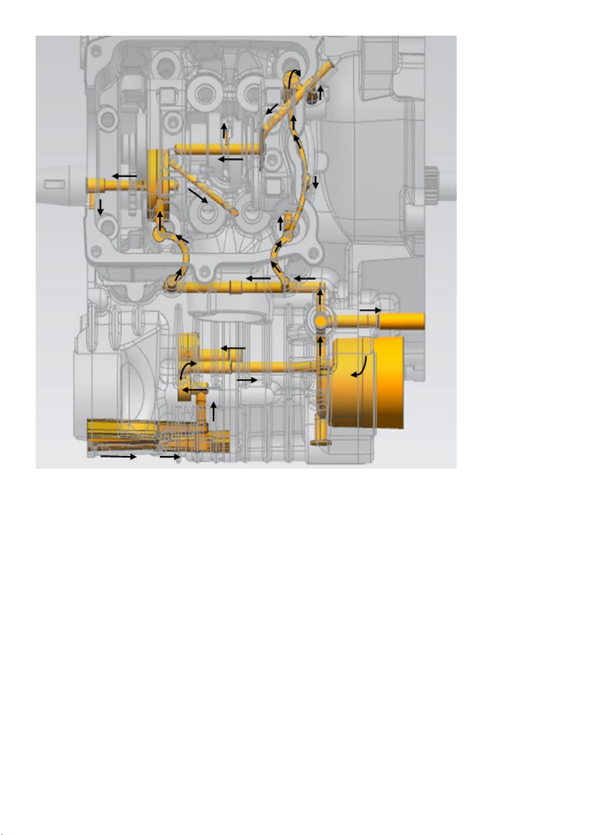
Lubrication system ..................................................................................... 6
1.Diagram of lubrication system...................................................................... 6
2. Maintenance information ......................................................................... 8
3. Common failure phenomenon/troubleshooting ....................................................... 8
4. Oil pump ....................................................................................... 9
Cylinder head cover, cylinder head ...................................................................... 11
1. System components ............................................................................ 11
2. Maintenance information ........................................................................ 13
3. Fault phenomenon/fault analysis.................................................................. 14
4. Cylinder compression test ....................................................................... 15
5. Cylinder head cover............................................................................. 15
6. Cylinder head .................................................................................. 16
7. Guide bar ..................................................................................... 24
8. Tension strip ................................................................................... 25
9. Tensioner ..................................................................................... 27
Cylinder, piston....................................................................................... 28
1. System components ............................................................................ 28
2. Maintenance information ........................................................................ 29
3. Troubleshooting ................................................................................ 29
4. Cylinder ....................................................................................... 29
5. Piston......................................................................................... 30
Left crankcase cover, continuously variable clutch sub-assembly ............................................ 33
1. System components ............................................................................ 33
2. Maintenance information ........................................................................ 35
3. Common failure phenomenon/troubleshooting ...................................................... 35
4. Left crankcase cover ............................................................................ 36
5. CVT clutch sub-assembly........................................................................ 37
Right crankcase cover, magneto ........................................................................ 40
1. System components ............................................................................ 40
2. Right crankcase cover / magneto stator............................................................ 41
3. Magneto rotor .................................................................................. 43
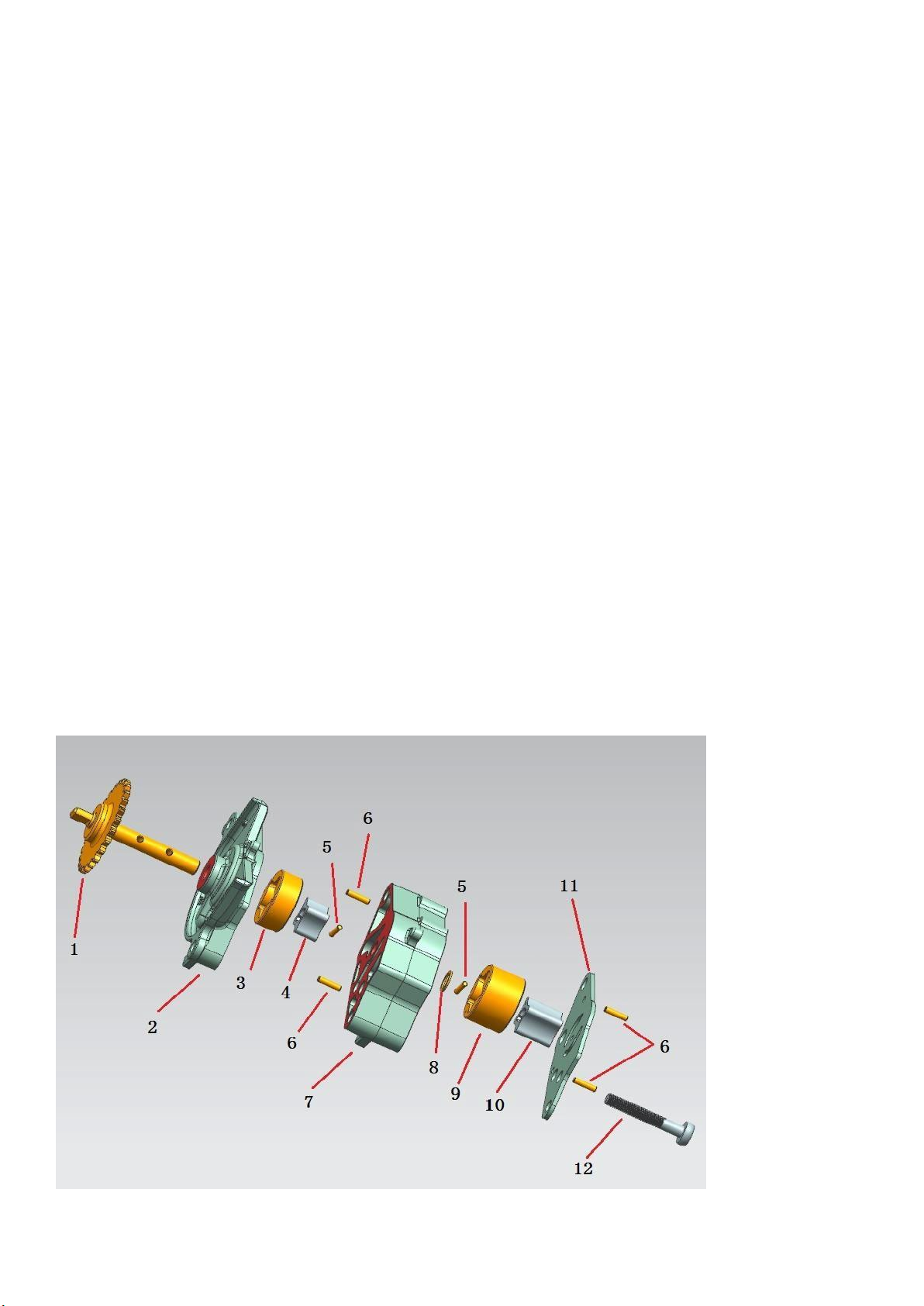
4. Water pump ................................................................................... 45
Gearbox............................................................................................. 49
1. System components ............................................................................ 49
2.Maintenance information ......................................................................... 50
3. Fault phenomenon/fault analysis.................................................................. 50
4. Disassembly and decomposition of the gearbox..................................................... 51
Five, gearbox gear, bearing inspection............................................................... 52
6. Gear box assembly ............................................................................. 53
Crankcase ........................................................................................... 54
1. System components ............................................................................ 54
2. Maintenance information ........................................................................ 55

5/ 63
3. Common failure phenomenon/troubleshooting ...................................................... 56
Fourth, the decomposition of the crankcase .......................................................... 57
5. Assembly of the crankcase ...................................................................... 60
Sixth, left and right crankcase suspension disassembly, inspection ...................................... 62
Seven, fine filter .................................................................................. 62

6/ 63
Lubrication system
1. Diagram of lubrication system

7/ 63

8/ 63
2. Maintenance information
General information
1. This chapter introduces the structural composition of the lubrication system and the maintenance of related parts.
2. The maintenance of the oil pump can be carried out on the whole vehicle without dismantling the engine separately.
3. The maintenance steps in this chapter must be carried out only after the engine oil has been drained.
4. When disassembling and installing the oil pump, be careful not to let dust and dirt enter the engine.
5. If the wear of any part of the oil pump exceeds the maintenance threshold, the entire oil pump assembly should be
replaced.
Specification
Project
Standard
Remark
Engine Oil
Capacity
Drain the oil for normal maintenance
(replace filter element)
1.75L ( 1.85 US qt, 1.54 lmp qt )
Drain the oil for normal maintenance
(without changing the filter element)
1.55L ( 1.64 US qt, 1. 36 lmp qt )
Drain the oil and remove the right
cover for normal maintenance
(replace the filter element)
1.8L ( 1.9 US qt, 1.5 8 lmp qt )
Drain the oil and remove the right
cover for normal maintenance
(without replacing the filter element)
1.6L ( 1.69 US qt, 1.41 lmp qt )
Disassembly and reassembly of the
whole machine
2.0L (21 US qt, 1.76 lmp qt )
recommended engine oil API SN grade or higher
motorcycle special motor oil
Torque value
Bolt model
Assembly position
Quantity
Torque ( Nm )
Remark
M6×60 hex flange bolts Oil pump locking bolt 2 11 ± 1.5 Nm -
tool
1. Torque wrench + 8# sleeve;
2. 8#-T-shaped socket wrench;
3. Common failure phenomenon/troubleshooting
1. Engine oil level is too low
·Engine oil leakage
Worn or improperly installed piston rings
·Cylinder wear
Abrasion of seals such as valve guides and valve rod diameter oil seals
2. The oil is dirty
·No regular oil change
·Poor gasoline quality
·Piston ring wear
·Oil oxidation

9/ 63
4. Oil pump
to disassemble
Before disassembling the oil pump, do the following:
· Remove the muffler. (Refer to the ZT350T-D maintenance manual for disassembly and assembly-- 2.
Maintenance-air filter (filter element)-bolts and nuts of the muffler)
· Remove the right crankcase cover of the engine. (Refer to ZT1P77MP engine maintenance manual for
disassembly and assembly--right crankcase cover, magneto-right crankcase cover, magneto stator)
· Remove the magneto rotor. (Refer to ZT1P77MP engine maintenance manual for disassembly and assembly -
right crankcase cover, magneto - magneto rotor)
·Remove the 5×5.7×16 half-round key and the large electric starter gear. (Refer to ZT1P77MP engine maintenance
manual for disassembly and assembly - magneto rotor)
①Use an 8#-T socket wrench to remove the 2 oil pump locking bolts (rotate counterclockwise).
②Take out the 2 oil pump bolts , and take out the oil pump assembly and the oil pump
chain together.
Install
①Put one end of the oil pump chain on the
driven sprocket of the oil pump, and the
other end on the driving gear of the oil pump
at the crankshaft end, align the oil pump
shaft with the oil pump installation hole on
the box body, and align the oil pump
positioning pin with the box body. Install the
oil pump on the upper positioning pin hole
and press it in place ( Note : spray oil on the
chain, inner and outer rotors of the oil
pump); then install 2 oil pump bolts, use a torque wrench (or air batch) and 8 #Tighten the bolt with the sleeve, and
the bolt locking torque is 11±1.5N.
·Install 5×5.7×16 semicircle keys and large gear for electric starter. (Refer to ZT1P77MP engine maintenance manual
for installation - right crankcase cover, magneto - magneto rotor)
Oil pump chain

10/ 63
·Install the magneto rotor. (Refer to ZT1P77MP engine maintenance manual for installation - right crankcase cover,
magneto - magneto rotor)
·Install the right crankcase cover of the engine. (Refer to ZT1P77MP engine maintenance manual for installation -
right crankcase cover, magneto - right crankcase cover, magneto stator)
·Install the muffler. (Refer to the ZT1P77MP maintenance manual for installation -- 2. Maintenance-air filter (filter
element)-bolts and nuts of the muffler)
Disassembly/installation
Disassemble in the following order
· M6×40 cross recessed pan head screw
· ZT1P72MN oil pump cover
·Inner rotor JBZ-29-18
·Outer rotor JBZ-29-18
· 2.5×12 cylindrical pin
· 8.6×11.5×1 thrust washer
· ZT1P72MN oil pump lower case
· 3×12 cylindrical pins
·Inner rotor JBZ-29-11
·Outer rotor JBZ-29-11
· 2.5×12 cylindrical pin
· ZT1P72MN oil pump upper casing
· ZT1P72MN oil pump shaft assembly
Please assemble in the reverse order of disassembly
(Note: During assembly, oil should be applied to the inner and outer rotors to fully lubricate the inner cavity of
the oil pump)
Bolt: M6×40 cross recessed pan head screw (tighten with a cross screwdriver or air batch + cross batch head)
Torque: 5~7N.m

11/ 63
No. Name Quantity
1 ZT1P72MN oil pump shaft assembly 1
2 ZT1P72MN oil pump upper housing 1
3 External rotor JBZ-29-11
1
4
Internal rotor JBZ-29-11
1
5 2.5x12 cylindrical pin
2
6 3x12 cylindrical pin
4
7 ZT1P72MN oil pump lower housing
1
8
86x11.5x1 thrust spacer
1
9 External rotor JBZ-29-18 1
10 Internal rotor JBZ-29-18 1
11 ZT1P72MN Oil Pump Cap 1
Cylinder head cover, cylinder head
1. System components
8
7
6
5
4
3
2
1
23
18
15
16
17
11
9
10
24
Valve disassembly reference
chart, intake valve exhaust
valve disassembly structure
is the same.
13
14
22
2120
19
12
25
26
27
28

12/ 63
Parts information
Serial
number
Name Quantity Serial
number
Name Quantity
1 6.3×12×1.6 copper gasket 1 19 φ11.11×φ1.78 fluorine rubber O-
ring 1
2 M6×16 hex flange bolts 1 20 GB276-6002-RS/P5C3 deep
groove ball bearings 1
3 M6×10 top pin bolt 1 21 ZTIP77MP valve Into 2 row
2
4 ZT1P77MP cylinder head
clamp bracket 1 22 φ17.2×φ25×1 valve spring base 4
5 LMAR8A-9 spark plug 1 23 φ5.0 valve rod diameter oil seal 4
6 AYM8-M8×38 double head
10.9 grade stud 2 24 ZT1P77MP valve outer spring 4
7 ZT1P77MP cylinder head 1 25 ZT1P77MP valve inner spring 4
8 ZT1P72MN cylinder head
pressure plate 1 26 ZT1P77MP valve spring bearing
plate 4
9 ZT1P77MP intake/exhaust
rocker arm parts 1/1 27 ZT1P58MJ valve lock clip 8
10 M6×10 top pin bolt 4 28 Φ8.85 valve clearance
adjustment pad 4
32
33
31
30
29
34
35
36

13/ 63
11 ZT1P77MP rocker limit block 2 29
M6×30 hexagonal flange bolts
(environmental protection color
zinc)
6
12 M5×15-5# hexagon socket
head screw (oxidized black) 2 30
M6×10 top pin bolt
(environmental protection color
zinc)
1
13 Water and oil shared sensor 1 31 ZT1P77MP high-pressure fuel
pipe bracket (short wheelbase) 1
14 9 x 2 EPDM O-rings 1 32 ZT1P77MP cylinder head cover
harness bracket 1
15 ZT1P77MP intake and
exhaust rocker shaft 2 33 ZT1P77MP cylinder head cover-
B 1
16 ZT1P77MP camshaft bearing
pressure plate 1 34 ZT1P77MP cylinder head cover
air balance tube 1
17 M6×16 top pin bolt 1 35 ZT1P77MP high-pressure fuel
pipe bracket (long wheelbase) 1
18 ZT1P72MN decompression
camshaft parts 1 36 ZT1P72MN cylinder head cover
rubber gasket 1
2. Maintenance information
General information
1. For the maintenance of the cylinder head cover and cylinder head, the engine must be removed from the frame. (For
the engine to be removed from the vehicle, refer to the ZT350T-D Maintenance Manual - 11. Vehicle Engine
Disassembly)
2. Disassemble the cylinder head cover and cylinder head. The engine oil does not need to be released. The rear wheel
and the main bracket can be used to stand the engine stably.
3. Before disassembly, the foreign matter and dust on the cylinder head cover and the joint surface of the cylinder head
need to be removed.
4. After removing the cylinder head cover and before removing the cylinder head, check the timing and turn the piston
to the top dead center.
5. When disassembling, the disassembled parts must be packed in a clean box and marked to prevent wrong assembly
during assembly.
6. When removing the cylinder head, first remove the 2 M8×1×117 hexagonal flange bolts on the side, and finally remove
the 4 M10×1.25 hexagonal flange nuts from the cylinder head.
7. When disassembling the cylinder head, it is forbidden to bump or scratch the joint surface of the cylinder head.
8. When disassembling and assembling the cylinder head, the cylinder head gasket cannot be reused to prevent blow-
by and air leakage.
Bolt torque value
Bolt model Assembly position quantity Torque
( N•m ) Remark
M6×30 hex flange bolts Cylinder head cover bolts 6 1 2 ± 1 .5 -
M8×1×117 hex flange bolts cylinder head bolts 2 2 0 ±2 -
M10×1.25 hexagon flange nut cylinder head nut 4 5 5 ±5 -
M6×10 top pin bolt - 10 1 0 ± 1 -

14/ 63
M6×22 hexagon flange full thread
bolts Thermostat lock bolt 2 1 2 ± 1 .5 -
M6×16 hex flange bolts - 3 1 2 ± 1 .5 -
LMAR8A-9 spark plug - 1 1 4 ± 1 -
tool
1. Pliers.
2. T-shaped sleeve -8#.
3. T-shaped socket-10# / torque wrench+10# socket.
4. T-shaped socket-14# / torque wrench+14# socket.
5. 5# inner hexagon.
6. 6# inner hexagon.
7. Valve spring top clamp.
8. 22# open-end wrench.
9. 17# plum wrench
10. Spark plug sleeve.
11, 10# inner hexagon.
3. Fault phenomenon/fault analysis
When the cylinder head of the engine fails, it will affect the performance of the engine at least, and it will make the
engine difficult to start. Troubleshooting can be done by detecting cylinder pressure, endoscope and other methods.
1. When the engine starts, the idling speed is unstable, or it is difficult to start
• The valve clearance is incorrect.
·Wrong timing, wrong teeth.
·The valve spring is broken.
·The air valve is not closed tightly and leaks air.
·The spark plug has serious on deposits, and the ignition energy is not enough.
·The spark plug is loose and leaks air.
·Cylinder head gasket gas blowing.
2. After the engine is running, there is abnormal sound
· The valve clearance is incorrect.
·The valve spring is broken.
· Valve seat ring wear.
· The camshaft throwing block is broken.
• Camshaft bearings are worn or damaged.
·The tensioner is damaged.
·Intake and exhaust valve rocker arm bearings are worn or damaged.
·The limit block of the rocker arm is broken.
·Excessive motorcycle carbon deposits in the engine, resulting in deflagration.
3. After the engine heats up, the exhaust gas is abnormal
·The oil seal of the valve stem diameter is worn or damaged.
• Valve guides are worn or damaged.
·The cylinder head gasket is damaged.

15/ 63
4. The engine is started electrically, and the crankshaft rotates without cylinder pressure or with very little
cylinder pressure
·The valve spring is broken.
·The valve is broken.
·Cylinder head gasket gas blowing.
·The spark plug is loose and leaks air.
· Excessive motorcycle carbon deposits on the valves cause the valves to not close tightly.
4. Cylinder compression test
1. Preheat the engine to the normal operating temperature, stop the engine, pull out the spark plug cap and remove the
spark plug (refer to ZT1P77MP maintenance manual for disassembly - 2. Maintenance - spark plug).
2. Install the cylinder pressure gauge connector into the spark plug hole.
3. Fully open the throttle, press the start switch, and use the starter motor to drive the crankshaft and piston to run until
the cylinder pressure gauge reading stops rising (starter motor running time ≤ 15s).
Engine speed: 480-525r/min
Compression pressure: 750-1050KPa (7.65-10.71 Kgf/cm 2 , 108.8-152.3 psi)
①If the measured cylinder pressure is larger than the normal value, it means that there is motorcycle carbon deposit
on the top of the piston or the wall of the cylinder.
②If the measured cylinder pressure is lower than the normal value , pour a small amount of clean engine oil from the
spark plug, turn the crankshaft a few times, so that the piston ring and cylinder wall are evenly covered with oil film, and
retest the cylinder pressure. If the cylinder pressure measured after pouring oil is greater than the last cylinder pressure
value, please dismantle the machine and check the piston and piston ring.
Failure analysis:
a. Piston ring wear.
b. Cylinder wear.
③If the cylinder pressure measured by pouring in the engine oil is the same as the last time (the cylinder pressure is
too small), first measure whether there is any abnormality in the valve clearance of the intake and exhaust valves, and
then disassemble the machine to check whether there is leakage of the intake and exhaust valves, the cylinder block
and cylinder pressure. Check whether the coating of the head gasket is damaged or blown by gas.
5. Cylinder head cover
Cylinder head cover removal
1. As shown in the figure, use the T rod -8# to remove the cylinder head cover locking bolt, and remove the cylinder
head cover wiring harness support, cylinder head cover, and cylinder head cover sealing ring.

16/ 63
Cylinder head cover installation
1. As shown in the figure, after removing the plane sealant, oil stains and dust on the joint surface of the cylinder head
and the cylinder head cover, apply an appropriate amount of plane sealant on the position shown in the figure. Check
the cylinder head cover sealing ring and wire harness bracket on the cylinder head cover. After confirming that the
installation is in place, install the cylinder head cover assembly to the corresponding position of the cylinder head. Use
M6×30 bolts to pre-tighten the cylinder head cover and tighten it with a fixed torque, 1 2 ± 1.5N •m . And check the
installation of the high-pressure oil pipe support, pre-tighten the support with M6×10 bolts and tighten it with a fixed
torque, 1 0 ± 1 N•m .
6. Cylinder head
Cylinder head removal
1. Use a T-shaped sleeve -8# to remove the thermostat bolt and take off the thermostat, and use the 5# and 10# inner
hexagonal wrench to remove the M14×1.5 screw plug and M30×1.5 screw plug on the right crankcase cover respectively.
Aluminum plug, and remove the O-ring.
2. Insert a 14#-T-type socket wrench from the M30×1.5 aluminum screw plug hole and set it on the magneto rotor locking
bolt, then turn the crankshaft clockwise to align the T point mark on the flywheel with the M14×1.5 screw. The plug hole
marks the gap. At the same time, the top dead center marking line on the timing driven sprocket should also be aligned
with the raised marking line on the cylinder head.
Note: Once the marking line at point T turns over the marking line when turning the flywheel, it cannot be turned
back to the point in the opposite direction. It is necessary to turn the crankshaft clockwise two times again to
re-align the point! ! !
Align
Align
Short wheelbase
only with this
bracket
Long wheelbase only
with this bracket

17/ 63
3. As shown in the picture, use T bar -8# to remove the tensioner, timing driven sprocket fixing bolts, and timing driven
sprocket (refer to ZT1P77MP engine maintenance manual for disassembly and assembly - cylinder head cover,
cylinder head - tensioner) .
4. As shown in the picture, first remove 2 pieces of M8×1×117 hexagonal flange bolts on the side of the cylinder head
with T rod -10#, and then use wrench -14# to remove 4 pieces of M10×1.25 from the opposite corner of the cylinder
head and lock the nuts.
5. As shown in the figure, remove the cylinder head, cylinder head gasket and positioning pin.
Cylinder Head Disassembly
1. Use a 6#-hexagon socket to remove the intake manifold subassembly and heat insulation pad (Note: the O-ring of
the heat insulation pad must not be damaged or broken).
2. As shown in the figure below, use a 22# open-end wrench to remove the oxygen sensor (the long-wheelbase version
has it, and the short-wheelbase version has an oxygen sensor), and T-bar-8# to remove the cylinder head clamp bracket

18/ 63
(short-wheelbase model does not have an oxygen sensor installed). Remove the spark plug with a spark plug socket.
Use a 17# plum wrench to remove the water oil temperature sensor.
3. As shown in the figure below, loosen the cylinder head pressure plate and camshaft pressure plate bolts, and remove
the cylinder head pressure plate and camshaft pressure plate.
4. As shown in the figure below, use a 5# inner hexagon to remove the rocker arm limit block bolt, and remove the rocker
arm limit block, rocker shaft, and intake and exhaust rocker arms, and valve adjustment gaskets.
Camshaft pressure plate

19/ 63
5. As shown in the picture, screw two M6 bolts into the threaded holes of the camshaft, keep the camshaft angle
consistent with the T point of the alignment timing or slightly rotate counterclockwise to an appropriate angle, and remove
the camshaft.
6. Use valve spring overhead pliers to remove the valve lock clip (do not compress the valve spring excessively). After
taking out the valve lock clip, remove the valve spring retainer, valve inner and outer springs, valve stem diameter oil
seal (The removed valve stem diameter oil seal cannot be used again ), valve spring base, and valve in sequence.
7. As shown in the figure, remove the carbon deposits in the combustion chamber. Do not scratch the joint surface of
the cylinder head and the surface of the valve seat ring.
Inspection of cylinder head parts:
1. Inlet and exhaust rocker shaft
a. There is no abnormal wear on the intake and exhaust rocker shafts.
2. Intake rocker arm, exhaust rocker arm
a. The intake rocker arm (mark I) and the exhaust rocker arm (mark E) have no abnormal wear.
Locking Clip

20/ 63
b. The intake and exhaust rocker rollers rotate smoothly without abnormal noise.
3. Intake and exhaust valve springs
a. The intake and exhaust springs have no cracks and abnormal wear.
4. Camshaft
a. Check whether the throwing block of the camshaft pressure reducing valve returns normally.
b. Check whether the camshaft pick is abnormally worn.
c. Turn the camshaft bearing by hand, it should turn smoothly without abnormal noise.
5. Intake valve, exhaust valve, cylinder head seat ring
a. Check whether the diameter of the valve stem is abnormally worn, bent or ablated, and check whether the valve can
move smoothly in the valve guide.
b. Check the valve seat surface for abnormal wear and erosion.
C. Check the seat surface of the cylinder head, no abnormal wear and ablation.
Valve seat ring
surface
Camshaft bearings
Pressure reducing valve dump block
Exhaust rocker arm logo
Intake rocker arm label
Cylinder head
seating surface
Valve stem diameter
Valve guide inner
Camshaft runout
ZT1P77MP valve outer spring
ZT1P77MP inner valve spring
Table of contents
Other Zontes Engine manuals
Popular Engine manuals by other brands

Briggs & Stratton
Briggs & Stratton 170700 Series Operating and maintenance instructions

EMAK
EMAK K1600 AVD operating manual

MTU
MTU 12 V 2000 G25 operating instructions

PCM
PCM 2007 5.0L MPI Owner's operation and maintenance manual

BONFIGLIOLI
BONFIGLIOLI C RAP Series Installation

Siemens
Siemens 1PM4 101 instructions

Oriental motor
Oriental motor K Series operating manual

woodmizer
woodmizer G26 Safety, Operation, Maintenance & Parts Manual

Oriental motor
Oriental motor PKP Series operating manual

M-Elec
M-Elec GD-5610 instruction manual

Ebmpapst
Ebmpapst M3G084-GF08-81 operating instructions

Power Fist
Power Fist 170S user manual