2-CYLINDER HEAD ASSEMBLY
9
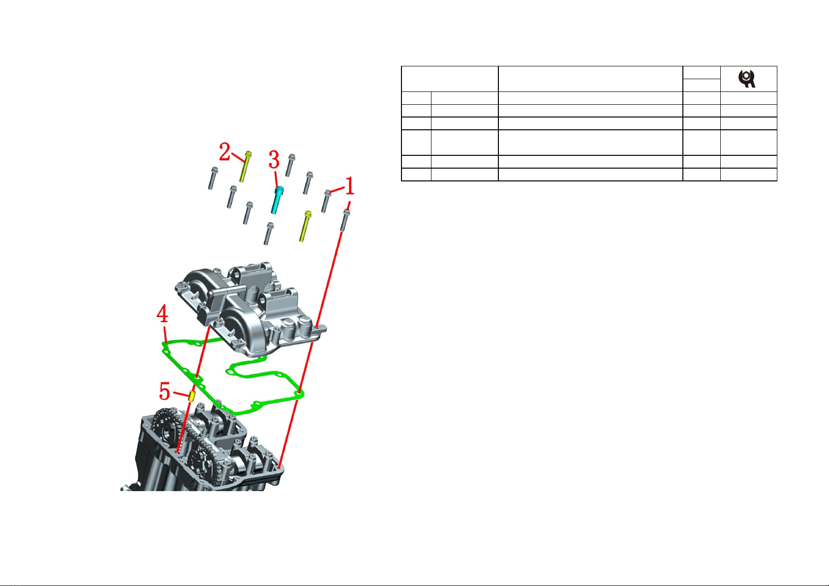
NO. PART NO. PART NAME QTY CAUTION
14051758-008000 ZT184MP intake camshaft sub-assembly 1
21050158-009000 3×27×19 slide tappet 4
34051758-009000 ZT184MP exhaust camshaft sub-assembly 1
Fig.4 CYLINDER HEAD
ASSEMBLY
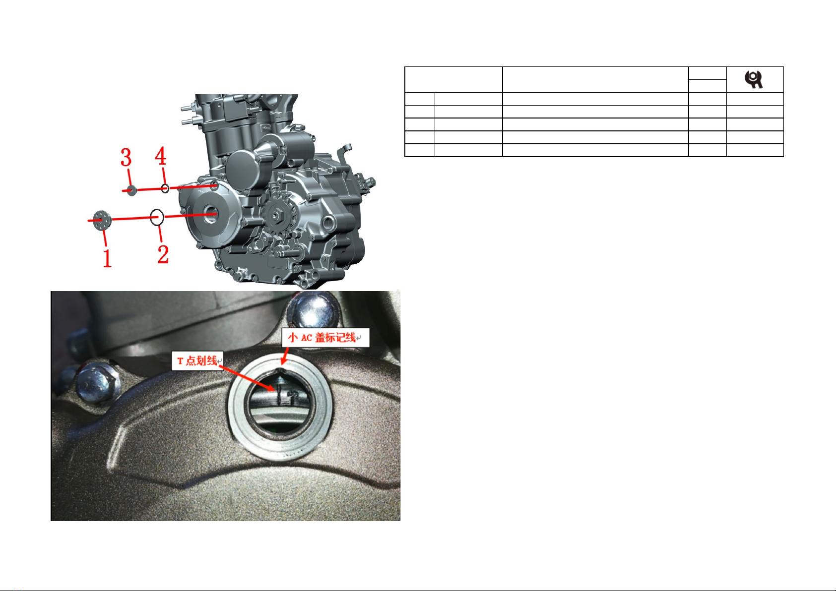
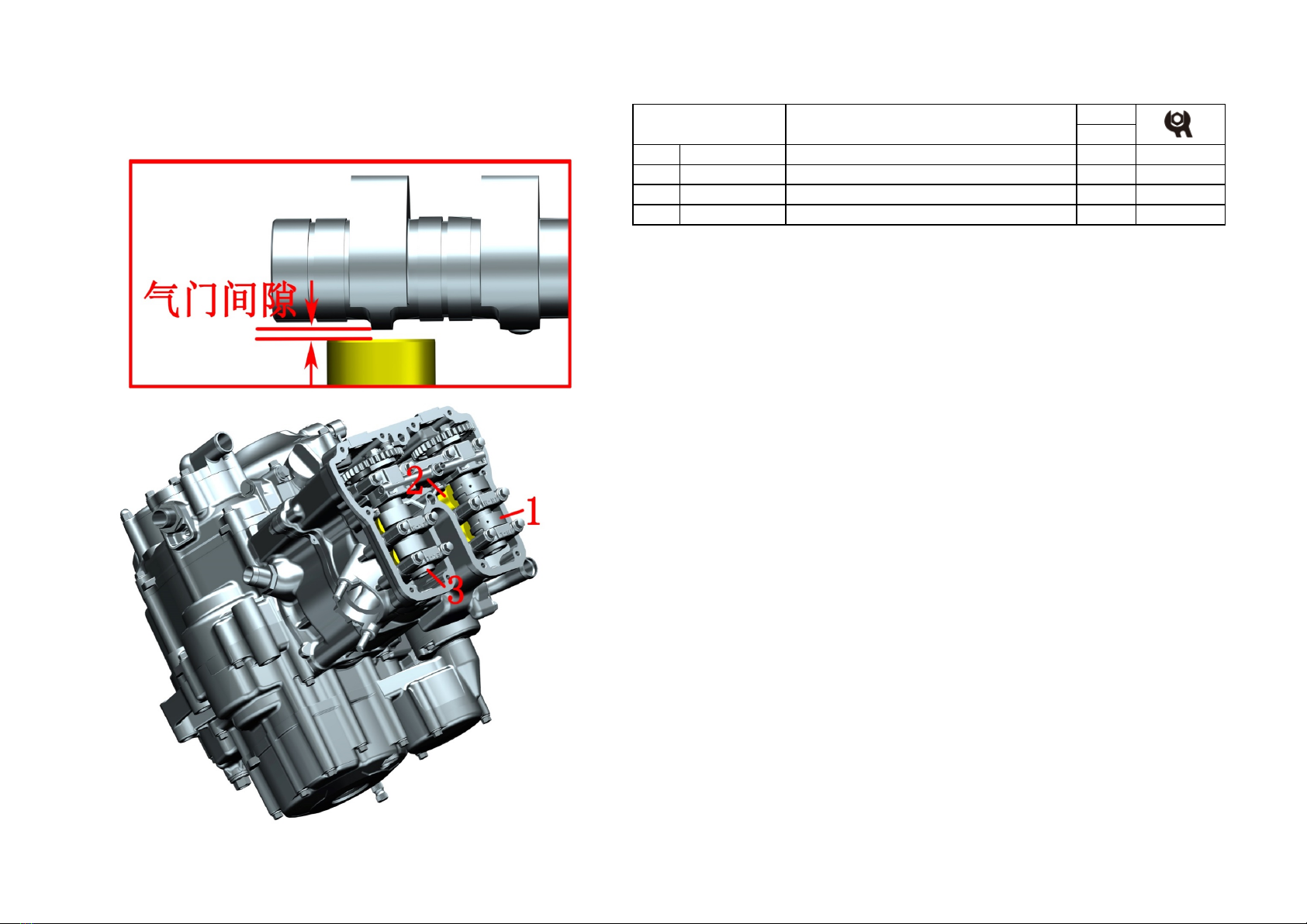
Adjust valve clearance
PROCEDURE:
●Adjust the valve clearance
Rotate the intake and exhaust camshafts so that the base circle of the intake and exhaust
camshafts is directly on the tappet, and the camshaft can rotate flexibly.
Use a feeler gauge to measure the valve clearance.
Standard interval of intake valve clearance: 0.13-0.19mm
Standard interval of exhaust valve clearance: 0.24-0.30mm
If it does not meet the standard, remove the intake and exhaust camshafts, take out the
tappet, and replace the valve clearance adjustment pad under the tappet.
After the replacement is completed, measure the valve clearance with a feeler gauge
again, the adjustment is successful if it is qualified, otherwise continue to replace the valve
clearance adjustment pad.
Notice:
●When measuring the clearance of the right exhaust valve, you need to rotate the
pressure reducing mechanism by hand until it is fully opened before measuring.
●The adjusting pad needs to be placed in place, and the cylinder head cannot be tilted or
dumped after adjusting the valve clearance; Camshaft lock can be used to prevent the
adjustment pad from dislocation.