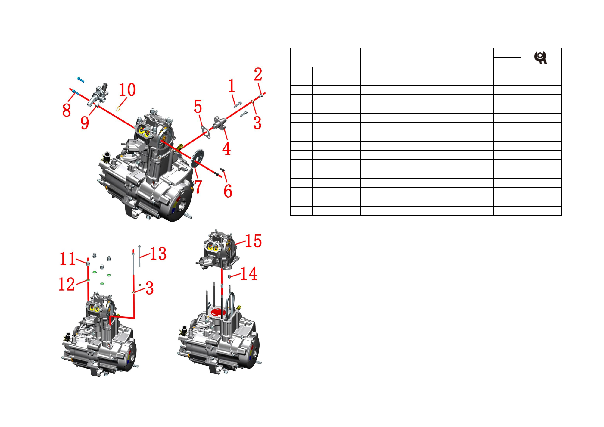
2-Cylinder head assembly
6
CHK
ADJ
NO. PART NO.
1 1251112-002093 GB16674 M6×30 Hexagon flange bolts
2 1251100-067093 M6×10 top pin bolt (color Zinc)
3 1251513-001019 6.3×12×1.6 copper gasket
4 1051270-004000 ZT1P72MN tensioner sub-assembly
5 1051253-004000 30×38 Washer, tensioner
6 1251100-340094 M6×10 Hexagon flange bolts
7 1050157-012000 ZT163ML timing driven sprocket
8 1251100-061093 M6×22 Hex flang bolt thread
9 1271200-199000 KD200-U thermostat
10 1051468-010000 16.5×1.95 EPDM
11 1251300-093000 Non-standard cap nut M8×18
12 1051661-001000 Combined gasket φ9×φ18×2 (Dacromet)
13 1251112-007093 GB16674 M6×1055 Hexagon flange bolts
14 1251401-003000 φ10×14 dowel pin
15 4050657-006000 ZT163ML cylinder head sub-assembly
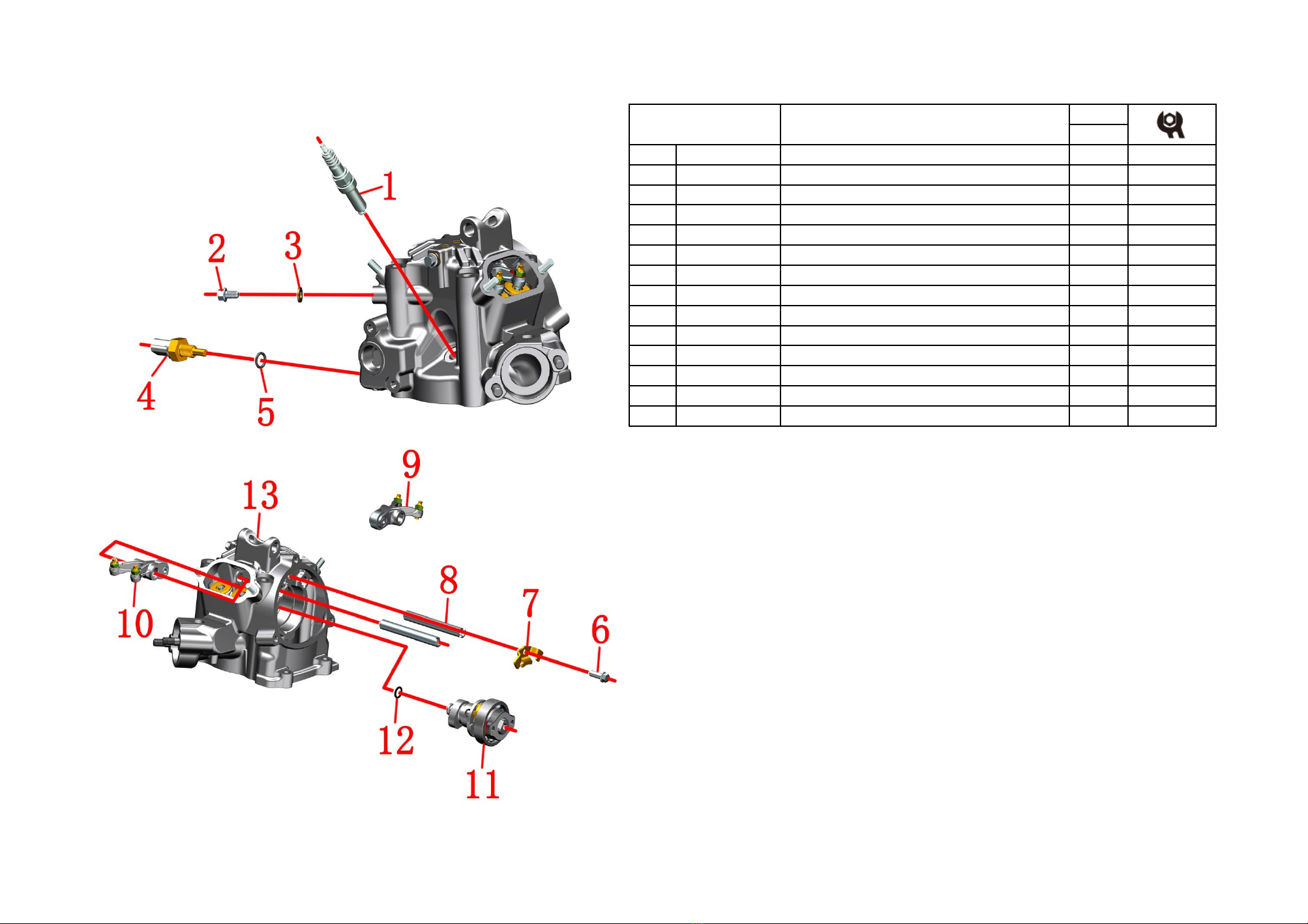
assembly Removal of cylinder head-2
●Removal of cylinder head-2
Use an 8# sleeve to pre-loosen the bolts ⑵, then remove the 2 bolts ⑴, and take out the tensioner ⑷and
gasket ⑸.
Use an 8# sleeve to remove the 2 bolts ⑹on the timing driven sprocket ⑺, and take out the timing driven
sprocket ⑺.
Use an 8# sleeve to remove 2 bolts⑻, and remove the thermostat ⑼and O-ring ⑽.
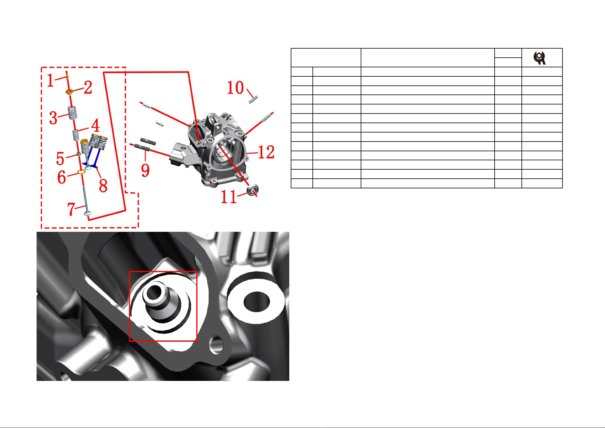
Use an 8# socket to remove 2 bolts ⒀, and take out 2 gaskets ⑶.
Use a 14# sleeve to remove 4 nuts ⑾, and take out 4 gaskets ⑿.
Grasp the cylinder head ⒂and remove it from the engine.
Note: 2 locating pins ⒁Be careful not to lose or drop them inside the engine.
During installation, it is necessary to use an 8# sleeve to remove the bolts ⑵and gaskets ⑶on the
tensioner ⑷, and then use tooling to retract the tensioner strut and put the tensioner ⑷back.
CAUTION:
●Do not let foreign objects fall into the engine during disassembly and installation.
●When installing the bolts at the timing sprocket ⑹, apply an appropriate amount of thread fastening glue
to the threads.
●The nut ⑾needs to be tightened diagonally to the appropriate torque standard during installation.