Zontes Euro V ZT152 User manual

ZT152 Engine Euro V
Service manual
2020/12/11

Page 1 ,Toatal 49 Pages
Pages
0Table of Contents………………………………………………………………………………………………………………………………………………………………………………………………… 1
1STEPS TO DRAIN ANTIFREEZE
1.1 Steps for discharging antifreeze………………………………………………………………………………………………………………………………… ………………………………………………… 4
2CYLINDER HEAD ASSEMBLY
2.1 Water pump assembly-1………………………………………………………………………………………………………………………………… ………………………………………………………… 5
2.2 Water pump assembly-2…………………………………………………………………………………………………………………………………………………………………………………………… 6
2.3 Outer parts of cylinder head………………………………………………………………………………………………………………………………………………………………………………………… 7
2.4 Cylinder head cover assembly……………………………………………………………………………………………………………………………………………………………………………………… 8
2.5 Cylinder head assembly-1………………………………………………………………………………………………………………………………………………………………………………………… 9
2.6 Cylinder head assembly-2………………………………………………………………………………………………………………………………………………………………………………………… 10
2.7 Cylinder head assembly-3………………………………………………………………………………………………………………………………………………………………………………………… 11
2.8 Cylinder head assembly-4………………………………………………………………………………………………………………………………………………………………………………………… 12
2.9 Cylinder head assembly-5………………………………………………………………………………………………………………………………………………………………………………………… 13
3CYLINDER BLOCK ASSEMBLY
3.1 Cylinder block assembly-1……………………………………………………………………………………………… ……………………………………………………………………………………… 14
4Steps of draining oil before removing side cover and box body
Oil drainine………………………………………………………………………………………………………………………………………………………………………………………………………… 15
5RIGHT CRANKCASE COVER ASSEMBL
5.1 ZT158MJ right crankcase cover assembly-1………………………………………………………………………………………………… …………………………………………………………………… 16
5.2 ZT158MJ right crankcase cover assembly-2………………………………………………………………………………………… …………………………………………………………………………… 17
5.3 ZT158MJ right crankcase cover assembly-3……………………………………………………………………………………………… ……………………………………………………………………… 18
5.4 ZT158MJ right crankcase cover assembly-4………………………………………………………………………………………… …………………………………………………………………………… 19
5.5 ZT158MJ right crankcase cover assembly-5…………………………………………………………………………………………………… ………………………………………………………………… 20
5.6 Clutch assembly-1…………………………………………………………………………………………………… ………………………………………………………………………………………… … 21
5.7 Clutch Assembly-2…………………………………………………………………………………………………… ………………………………………………………………………………………… … 22
5.8 Clutch assembly-3…………………………………………………………………………………………………… ………………………………………………………………………………………… … 23
5.9 Clutch assembly-4…………………………………………………………………………………………………… ………………………………………………………………………………………… … 24
Contents
Table of Contents

Page 2 ,Toatal 49 Pages
Pages
Contents
Table of Contents
6RIGHT CRANKCASE COVER ASSEMBL
6.1
Left crankcase cover assembly-1……………………………………………………………………………………………… …………………………………………………………………………………
25
6.2
Left crankcase cover assembly-2………………………………………………………………………………………… ………………………………………………………………………………………
26
7LEFT CRANKSHAFT BOX ASSEMBLY
7.1
ZT158MJ magneto rotor, crankshaft position sensor……………………………………………………………………………………………… ………………………………………………………………
27
7.2
ZT158MJ electric starter assembly -1…………………………………………………………………………………… …………………………………………………………………………………………
28
7.3
ZT158MJ electric starter assembly-2………………………………………………………………………………………… ……………………………………………………………………………………
29
7.4
ZT158MJ left crankcase assembly -1
30
7.5
ZT158MJ left crankcase assembly-2………………………………………………………………………………………… ……………………………………………………………………………………
31
7.6
ZT158MJ left crankcase assembly-3………………………………………………………………………………………… ……………………………………………………………………………………
32
7.7
ZT158MJ left crankcase assembly-4…………………………………………………………………………………………………… …………………………………………………………………………
33
7.8
ZT158MJ left crankcase assembly-5………………………………………………………………………………………………… ……………………………………………………………………………
34
7.9
ZT158MJ left crankcase assembly-6……………………………………………………………………………… ………………………………………………………………………………………… ……
35
8RIGHT CRANKSHAFT BOX ASSEMBLY
8.1
ZT158MJ oil pump assembly………………………………………………………………………………………… …………………………………………………………………………………… ………
36
8.2
ZT158MJ balance shaft assembly-1………………………………………………………………………………………… ……………………………………………………………………………………
37
8.3
ZT158MJ balance shaft assembly-2………………………………………………………………………………………… ……………………………………………………………………………………
38
8.4
ZT158MJ balance shaft gear assembly -1………………………………………………………………………………………… ………………………………………………………………………………
39
8.5
ZT158MJ shift mechanism assembly-1………………………………………………………………………………………… …………………………………………………………………………………
40
8.6
ZT158MJ shift mechanism assembly-2………………………………………………………………………………………… …………………………………………………………………………………
41
8.7
ZT158MJ right crankcase assembly-1………………………………………………………………………………………… …………………………………………………………………………………
42
8.8
ZT158MJ right crankcase assembly-2………………………………………………………………………………………………… …………………………………………………………………………
43
9Gear shifting and transmission mechanism components
9.1
Gear shifting and transmission mechanism components-1……………………………………………………………………………………………… …………………………………………………………
44
9.2
Gear shifting and transmission mechanism components-2………………………………………………………………………………………… ………………………………………………………………
45
9.3
Gear shifting and transmission mechanism components-3…………………………………………………………………………………… ……………………………………………………………………
46
9.4
Gear shifting and transmission mechanism components-4……………………………………………………………………………………………… …………………………………………………………
47
9.5
Gear shifting and transmission mechanism components-5…………………………………………………………………………………………………… ……………………………………………………
48
9.6
Gear shifting and transmission mechanism components-6………………………………………………………………………………………… ………………………………………………………………
49

Page 3 ,Toatal 49 Pages
Pages
Contents
Table of Contents
©Guangdong Tayo Motorcycle Technology Co., Ltd.
property in copyright
This manual is suitable for ZT125 series engines. All the materials, illustrations, photos, etc. collected in this manual are compiled according to the latest products. However, due to continuous product
improvement and other changes, there may be some inconsistencies between your engine and this manual.For colors or upgrades, please refer to the part codes on the official website. This manual will
not be listed in detail; If the part names in this manual are inconsistent with the official website, the official website shall prevail.

1- STEPS TO DRAIN ANTIFREEZE
4
CHK
ADJ
NO. PART NO.
PART NAME QTY CAUTION
1 1251100-067093
M6×10 top pin bolt (color zinc) 1 12±1.5N.m
2 1251513-001019 6.3×12×1.6 copper gasket
1
Fig.1 STEPS TO DRAIN
ANTIFREEZE Steps to drain antifreeze
PROCEDURE:
●As shown in the figure, find the bolt ⑴ on the right side of the engine, use an 8#T sleeve to unscrew and
remove the copper gasket ⑵, place a container under the drain hole, and prepare to receive antifreeze.
●
Locate the main water tank filling port on the right side of the vehicle steering column, press down and turn it
counterclockwise to remove the water filling port cap, the antifreeze will be discharged from the drain hole into
the container.
CAUTION:
●After the gasket(2) is removed, it is best to replace it with a new one to avoid water leakage.
●The tightening torque of bolt ⑴ is 12±1.5N.m.
●Antifreeze is corrosive to a certain extent, so be careful not to contaminate the engine and other parts, body,
clothing, etc. when discharging the antifreeze. If parts are accidentally contaminated with antifreeze, immediately
wipe them with a clean lint-free cloth. If clothing or skin is stained with antifreeze, immediately rinse with clean
water. If the antifreeze is splashed into the eyes, immediately rinse with plenty of water and observe to decide
whether to seek medical attention.
●
The disassembly of the engine should be carried out when the engine is cold. The first is to prevent burns. The
second is that most of the oil is in the crankcase when the engine is cold. At this time, there is no need to drain
the oil when removing the cylinder head assembly and the cylinder block assembly.

2-CYLINDER HEAD ASSEMBLY
5
CHK
ADJ
NO. PART NO.
PART NAME QTY CAUTION
1 1251112-002093
M6×30 Hexagon flange bolts (color zinc) 3 12±1.5N.m
2 1251401-001000 φ8×14 hollow positioning pin
2
3 1051656-002000 ZT158MJ water pump sealant
1
4 1051468-011000 18.2×2.4 EPDM O-ring 1
5 1051956-002000 ZT158MJ water pump leaking pipe 1
PROCEDURE:
●Use 8#T rod sleeve to remove the three bolts ⑴, remove the water pump, positioning pin ⑵, sealant ⑶ and
O-ring ⑷.
●Leaking pipe ⑸ can be removed by turning counterclockwise.
●Clean up the remaining sealant on the bonding surface.
CAUTION:
●There is still a part of antifreeze in the water pump. When disassembling, place a rag under the water pump to
prevent the antifreeze from directly contaminating the surface of the engine.
●When cleaning the remaining sealant, be careful not to allow foreign matter to enter the engine.
●The matching relationship between the position shown in the water pump shaft ② and the camshaft mounting
bolt ① is shown in the figure. The camshaft also serves as the driving tooth of the water pump.
Fig.1 CYLINDER HEAD
ASSEMBLY
Water pump assembly-1

2-CYLINDER HEAD ASSEMBLY
6
CHK
ADJ
NO. PART NO.
PART NAME QTY CAUTION
1 1251100-061093
M6×22 Hex flang bolt thread level 8.8 (color zinc) 3
2 1251100-067093
M6×10 top pin bolt (color zinc) 1
3 1251513-001019 6.3×12×1.6 copper gasket
1
4 4050968-001000 ZT1P58MJ water pump cover 1
5 1251401-001000 φ8×14 hollow positioning pin 2
6 1051468-013000 ZT1P58 water pump cover sealing ring 1
7 1051154-003000 GB894.1 Circlip for shaft φ10 (Dacromet plated) 1
8 1051968-009000 ZT1P58MJ water pump shaft 1
9 1051968-010000 ZT1P58MJ Water Pump Blade 1 20±1.5N.m
Fig.2 CYLINDER HEAD
ASSEMBLY
Water pump assembly-2
12±1.5N.m
PROCEDURE:
●Use 8#T rod sleeve to remove the three bolts ⑴ and then take off the water pump cover, positioning pin ⑸
and sealing ring ⑹.
●Use 8#T rod sleeve to remove the drain bolt ⑵, and remove the gasket ⑶.
●Use circlip pliers to remove the opening retaining ring ⑺, fix the water pump shaft ⑻, and rotate the water
pump blade ⑼ counterclockwise to remove the blade.
CAUTION:
●Open retaining ring ⑺ is for one-time use, and must be replaced after disassembly, so as to avoid plastic
deformation caused by disassembly, which may cause the fixation to fall off.
●The sealing ring ⑹ needs to be replaced after disassembly, otherwise it may cause the seal to not be in place
and cause water leakage.
●
When installing the water pump blade, it is necessary to apply a proper amount of thread fastening glue evenly
on the threads of the water pump shaft, and a proper amount of silicone oil on the contact surface of the water
pump blade and the water seal.

2-CYLINDER HEAD ASSEMBLY
7
CHK
ADJ
NO. PART NO.
PART NAME QTY CAUTION
1 1050954-026000 LSF oxygen sensor
1
2 1251100-061093
M6×22 Hex flang bolt thread level 8.8 (color zinc) 2 12±1.5N.m
3 1051956-001000 ZT158MJ thermostat sub-assembly
1
4 1051468-010000 16.5×1.95 EPDM O-ring 1
Fig.3 CYLINDER HEAD
ASSEMBLY
Cylinder head outer parts
PROCEDURE:
●Use 22# open-end wrench to remove the oxygen sensor ⑴.
●Use 8#T rod sleeve to remove the two bolts ⑵, and remove the thermostat ⑶ and the sealing ring ⑷.
CAUTION:
●The sealing ring ⑷ is for one-time use. It is recommended to replace it after disassembly to avoid leakage due
to improper sealing.

2-CYLINDER HEAD ASSEMBLY
8
CHK
ADJ
NO. PART NO. PART NAME QTY CAUTION
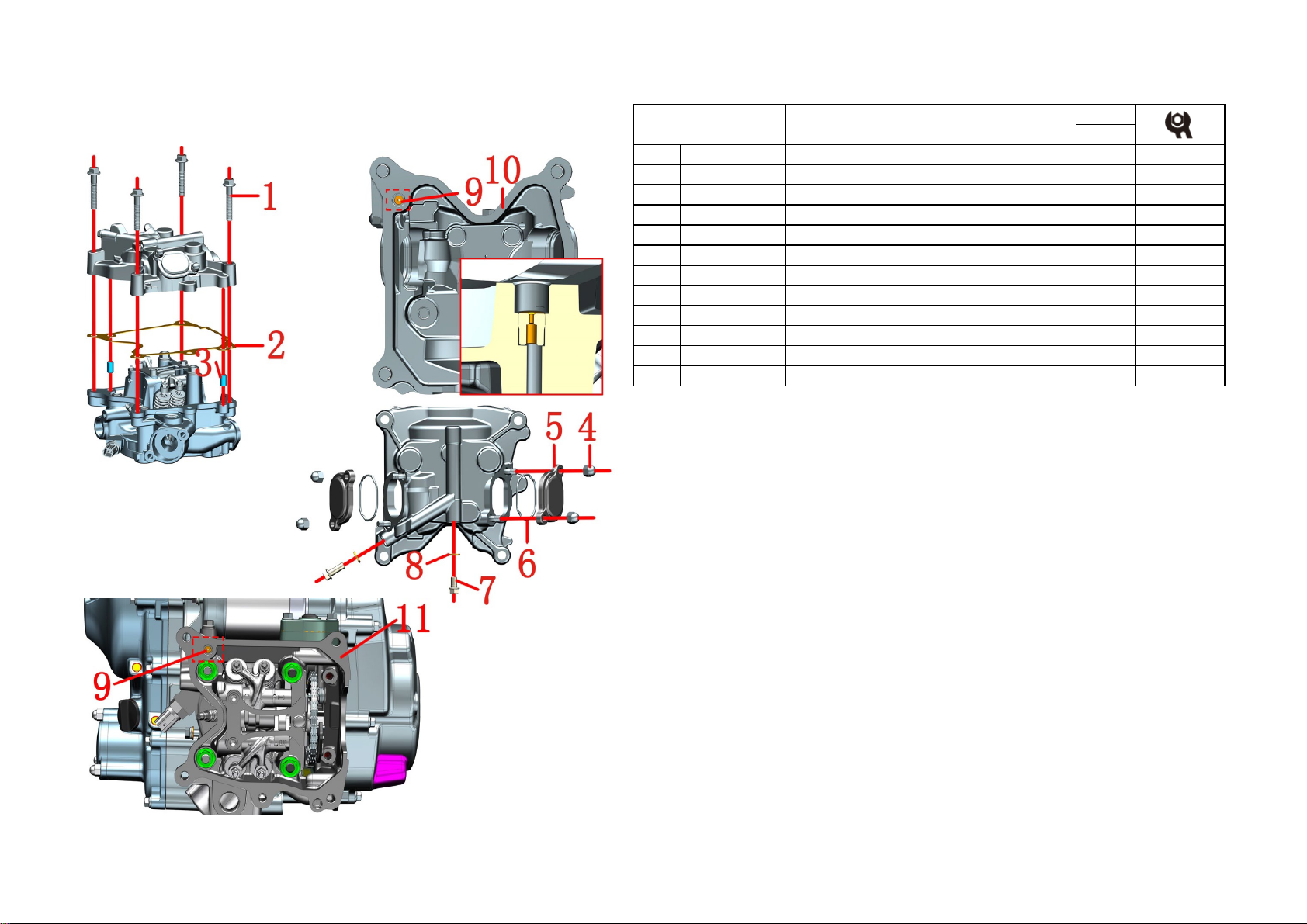
1 1250101-076093 GB16674 M8×45 (environmental protection color zinc) 4 25±3N.m
2 1051656-001000 ZT158MJ cylinder head cover gasket 1
3 1251401-001000 φ8×14 hollow positioning pin 2
4 1251300-056093 M6 cap type 9 grade nut (color zinc) 4 10±1.5N.m
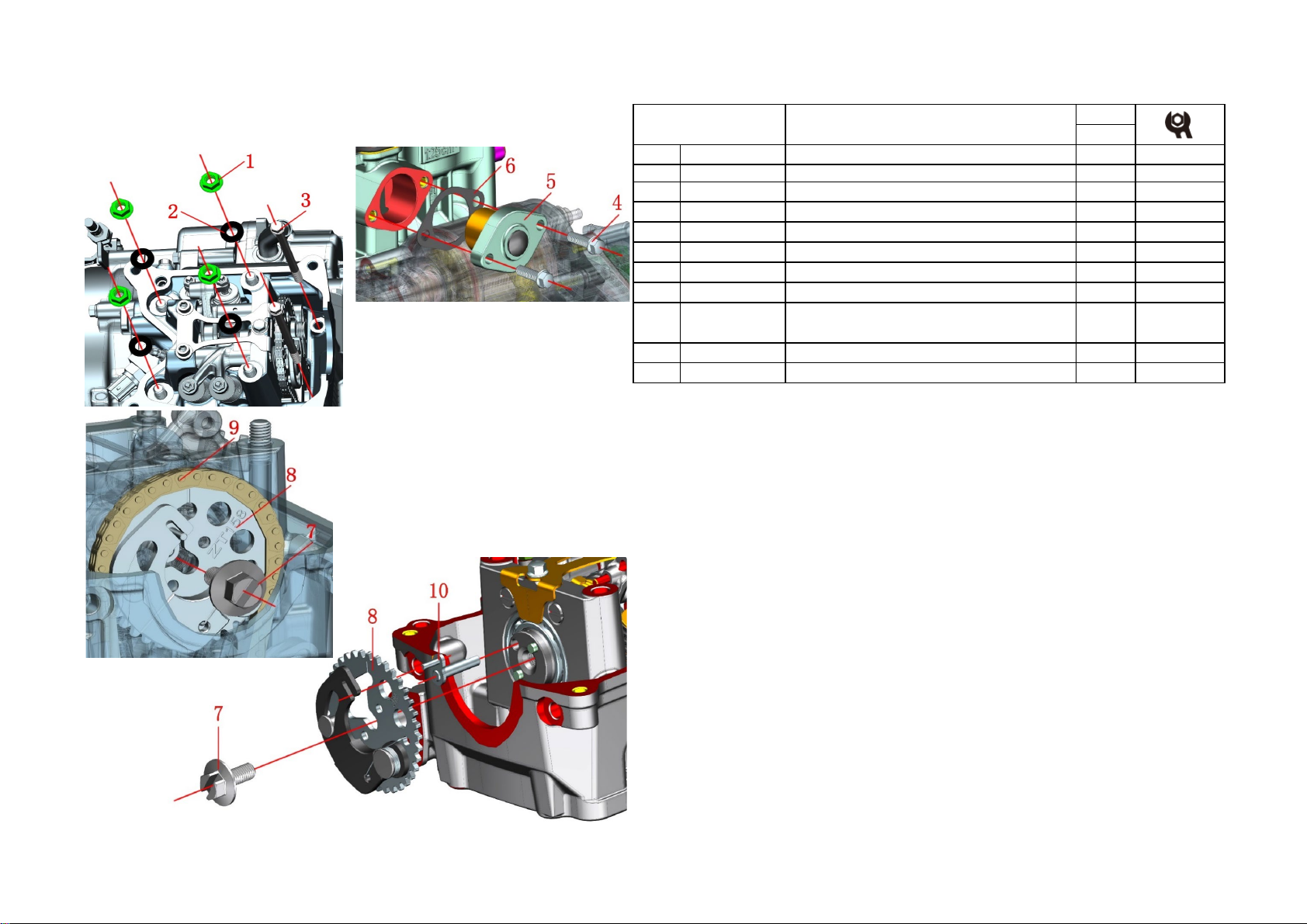
5 4050956-002000 ZT158MJ valve cover 2
6 1051468-009000 37×1.9 Acrylic O-ring 2
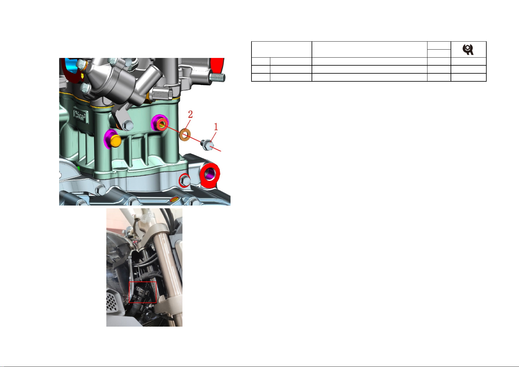
7 1251100-067093 M6×10 top pin bolt (color zinc) 1 10±1.5N.m
8 1251513-001019 6.3×12×1.6 copper gasket 3
9 1051754-002000 1.2×6×7 oil pin 1
10 4050756-002000 ZT158MJ cylinder head cover 1
11 4050656-004000 ZT158MJ cylinder head 1
Fig.4 CYLINDER HEAD
ASSEMBLY Cylinder head cover assembly
PROCEDURE:
●Use the 12#T rod sleeve to remove the four bolts (1) to remove the cylinder head cover, cylinder head cover
gasket (2) and positioning pin (3).
●Clean up the remaining sealant on the joint surface, and be careful not to drop foreign matter into the engine.
●Use a 10#T rod sleeve to disassemble the cover nut ⑷, and remove the valve chamber cover ⑸and the
sealing ring ⑹.
●Use 8#T rod sleeve to remove two bolts ⑺, and remove two washers ⑻.
CAUTION:
●The cylinder head cover gasket ⑵ is a one-time use, and must be replaced after disassembly, otherwise it
will cause a series of problems such as improper sealing and oil leakage.
●When cleaning residual sealant and other impurities, avoid foreign matter from entering the engine.
●The oil passing pin ⑼ is one of the passages of the oil circuit, which cannot be blocked, and there is an
interference fit with the cylinder head cover ⑽.Removing the oil pin may cause damage tothe joint surface.
●Both bolts ⑺ can be screwed out when the engine is running to check if there is oil leakage, as one of the
ways to check whether the oil is on the cylinder.
●Subsequent production will switch the oil passing pin ⑼on the cylinder head cover ⑽to the cylinder head
⑾.

2-CYLINDER HEAD ASSEMBLY
9
CHK
ADJ
NO. PART NO.
PART NAME QTY CAUTION
1 1251300-080094
black)
4 25±3N.m
2 1251500-079000 φ8.3×φ17×2 iron gasket 4
3 1251112-007093
M6×105 Hexagon flange bolts (color zinc) 2 12±1.5N.m
4 1251100-061093 M6×22 Hex flang bolt thread level 8.8 (color zinc) 2 12±1.5N.m
5 1051268-003000 ZT1P58MJ tensioner sub-components
1
6 1051668-006000 ZT1P58MJ Tensioner Gasket
1
7 1251100-164093 ZT1P58MJ camshaft bolt M8×1.25×20-10.9 grade
1 30±3N.m
9 1050156-005000 ZT158MJ timing chain 96 links SCZ-0404SV
1
10 1050168-001000 ZT1P58MJ decompression lever
1
8 1050156-002000 ZT158MJ timing driven sprocket decompression sub
-component 1
Fig.5 CYLINDER HEAD
ASSEMBLY
Cylinder head cover assembly-1
PROCEDURE:
●Use 8#T rod sleeve to remove two bolts (3).
●Use a 12#T rod sleeve to remove four nuts ⑴ and four washers ⑵.
●Use a 8#T rod sleeve to remove the two bolts ⑷ on the cylinder block, and remove the tensioner ⑸ and gasket
⑹to loosen the toothed chain ⑼.
●Use a 12#T rod sleeve to remove the bolt ⑺, remove the sprocket ⑻ and the decompression component ⑽,
and put the toothed chain ⑼ back into the engine.
●Pull up the cylinder head and remove the sub-components of the cylinder head.
CAUTION:
●
To disassemble the cylinder head, you must first disassemble the bolt (3) and then disassemble the nut (1), and
vice versa during assembly.
●
The bolt (3) is recommended to be replaced after disassembly. Because the bolt (3) is relatively long and bears
a large torque, it is recommended to replace it every time it is removed.
●If you need to take out the toothed chain later, just take it out with a magnetic tool.
●Be careful not to fall into the engine when disassembling bolts, nuts and other parts. If you accidentally fall
into the engine, try to suck it out with a magnetic tool, otherwise you need to further disassemble the engine to
take it out.
●The gasket ⑹ is for one-time use, it is recommended to replace it after disassembly.

2-CYLINDER HEAD ASSEMBLY
10
CHK
ADJ
NO. PART NO.
PART NAME QTY CAUTION
1 1050953-004000 CR8EI-8 spark plug (with nut)
1 14±1.5N.m
2 1050954-003000 Water and oil shared sensor
1 13±1.5N.m
3 1051454-009000 9×2 EPDM rubber O-ring
1
4 1251112-001093 M6×16 Hexagon flange bolts (color zinc) 1 12±1.5N.m
5 1251513-001019 6.3×12×1.6 copper gasket
1
6 1251100-067093
M6×10 top pin bolt (color zinc) 1 12±1.5N.m
7 1251201-001094
Internal hexagonal round screw 2 10±1.5N.m
8 1051368-003000 ZT1P58MJ camshaft bearing pressure plate
1
Fig.6 CYLINDER HEAD
ASSEMBLY
Cylinder head cover assembly-2
PROCEDURE:
●Use a 16# spark plug socket wrench to disassemble the spark plug ⑴, be careful not to drop the gasket on the
spark plug.
●Use 17#T rod sleeve to remove the water and oil shared sensor ⑵, and remove the sealing ring ⑵.
●Use 8#T rod sleeve to remove bolt ⑷, and remove gasket ⑸.
●Use 8#T rod sleeve to remove bolt ⑹, use 5# Allen wrench to remove two bolts ⑺, then bearing pressure
plate ⑻ can be removed.
CAUTION:
●
Spark plug is a consumable part. It is recommended to check the gap and color of the spark plug every 10,000
kilometers. The normal gap range is 0.7mm-0.8mm. The normal color is light brown. If the gap or color is
abnormal, replace the spark plug. The replacement should not exceed 30,000 kilometers at the latest .
●Both bolts ⑹ and bolts ⑺ need to be coated with appropriate thread fastening glue.

2-CYLINDER HEAD ASSEMBLY
11
CHK
ADJ
NO. PART NO.
PART NAME QTY CAUTION
1 1050168-007000 ZT1P58MJ intake and exhaust rocker arm shaft
2
2 1050168-033000 ZT1P58MJ intake rocker arm sub-assembly-B
1
3 1050168-034000 ZT1P58MJ Exhaust Rocker Arm Sub-assembly-B
1
4 1251100-225000 M5×0.5 valve clearance adjusting nut 4 9±1N.m
5 1251100-222000 M5×0.5×SR12 valve clearance adjustment screw
4
Cylinder head cover assembly-3
PROCEDURE:
●Pull out the two intake and exhaust rocker arm shafts ⑴ to remove the intake rocker arm ⑵ and exhaust
rocker arm ⑶.
●Adjust valve clearance
Use 8# torx wrench to loosen the nut ⑷, then use 3# open-end wrench to adjust the screw ⑸, use a feeler
gauge to measure the valve clearance, after adjusting to the corresponding clearance range, 3# open-end wrench
to fix the screw ⑸, 8# torx wrench lock Tighten the nut ⑷, tighten the torque to 9±1N.m, and finally measure
the gap again.
Intake valve clearance: 0.12±0.02mm, two intake valve clearance difference ≤0.02mm, exhaust valve
clearance: 0.20±0.02mm, two exhaust valve clearance difference ≤0.02.
CAUTION:
●Be sure to tighten the nut ⑷ according to the torque requirements, otherwise it may cause the screws and nuts
to loosen or damage the threads.
●
When assembling the intake and exhaust rocker arm, spray an appropriate amount of engine oil to lubricate the
contact surface with relative movement.
Fig.7 CYLINDER HEAD
ASSEMBLY

2-CYLINDER HEAD ASSEMBLY
12
CHK
ADJ
NO. PART NO.
PART NAME QTY CAUTION
1 1050168-007000 ZT1P58MJ intake and exhaust rocker arm shaft
2
2 1050168-033000 ZT1P58MJ intake rocker arm sub-assembly-B
1
3 1050168-034000 ZT1P58MJ Exhaust Rocker Arm Sub-assembly-B
1
PROCEDURE:
●Just pull out the camshaft sub-part ⑴ directly.
CAUTION:
●When assembling the camshaft, it is necessary to spray a proper amount of oil for lubrication, and check the
O-ring to avoid omissions.
●Bearing (3) is an interference fit. Generally, it is not recommended to disassemble if there is no fault.
Fig.8 CYLINDER HEAD
ASSEMBLY
Cylinder head cover assembly-4

2-CYLINDER HEAD ASSEMBLY
13
CHK
ADJ
NO. PART NO.
PART NAME QTY CAUTION
1 1050168-016000 ZT1P58MJ valve lock clip
8
2 1050168-015000 ZT1P58MJ valve spring retainer
4
3 1050168-014000 ZT1P58MJ exhaust valve spring
4
4 1051553-001000 φ5.0 valve stem diameter oil seal 4
5 1050168-018000 ZT1P58MJ valve spring base
4
6 1050168-011000 ZT1P58MJ intake valve
2
7 1050168-012000 ZT1P58MJ exhaust valve
2
PROCEDURE:
●Remove the valve:
Use a hollow sleeve (diameter 15±4mm can be used) to press down the valve spring retainer ⑵, after the valve
lock clip ⑴ is released, use a magnet to suck out the valve lock clip ⑴, then the valve spring retainer ⑵, valve
spring can be removed ⑶/⑷, pull out the valve ⑹/⑺ from below, use needle-nose pliers to clamp out the oil
seal ⑷ and the valve spring base ⑸.
●Assemble the valve:
Brush the intake and exhaust valves evenly with a layer of clean engine oil and insert them into the original
position of the cylinder head from bottom to top. Pay attention to distinguish the intake and exhaust. Place the
cylinder head on a clean, lint-free, soft cloth to prevent the installation joint surface from being scratched and
the seal is not in place to leak oil. Put the four valve spring bases ⑸ into the four valve rods respectively to make
them fall to the bottom. Put the four new oil seals ⑷ on the four valve stems respectively, and use an 8# sleeve to
push them into place, as shown in Figure ①. Put the exhaust spring ⑶ into the corresponding positions
respectively, put the four valve spring retainers ⑵ into the valve stem respectively, press the valve spring retainer
⑵with the hollow sleeve, and clamp a pair of valve locks ⑴ Put it into the gap between the valve spring retainer
⑵and the valve stem, loosen the sleeve, and the valve lock clamps the valve stem under the action of the spring and
the valve spring retainer ⑵.
CAUTION:
●Oil seal ⑷It is recommended to replace it after disassembly, so as to avoid the damage caused by the
disassembly process and the seal is not in place, so that the oil enters the combustion chamber and burns.
Fig.9 CYLINDER HEAD
ASSEMBLY
Cylinder head cover assembly-5

3-CYLINDER BLOCK ASSEMBLY
14
CHK
ADJ
NO. PART NO.
PART NAME QTY CAUTION
1 1051256-002000 ZT158MJ guide strip 1
2 1251401-001000 φ10×14 hollow positioning pin 4
3 1051668-003000 ZT1P58MJ cylinder block box gasket 1
4 1051655-001000 ZT1P52MI cylinder block cylinder head gasket 1
5 1251100-067093 M6×10 top pin bolt (color zinc) 1
6 1251513-001019 6.3×12×1.6 copper gasket 1
7 4050555-001000 ZT152MI cylinder block 1
Fig.1 CYLINDER BLOCK
ASSEMBLY
Cylinder assembly-1
PROCEDURE:
●Pull the guide bar ⑴ upwards.
●Pull the cylinder block directly upward, and remove the cylinder block ⑺, hollow positioning pin ⑵ and
gasket ⑶ from the crankcase.
●Remove the positioning pin ⑵ and gasket ⑷ from the cylinder block ⑹ respectively.
●Use 8# torx wrench to remove bolt ⑸, and remove washer ⑹.
CAUTION:
●Gasket ⑶ and gasket ⑷ are both disposable and must be replaced after disassembly.
●Guide bar ⑴ must be removed before disassembling the cylinder block ⑺. When assembling, the cylinder
block ⑺ is assembled first and then the guide bar ⑴ is inserted.
●
When installing the piston in the cylinder block, the "IN" on the piston faces the installation side of the engine
tensioner.

4-OIL DRAINING STEPS
15
CHK
ADJ
NO. PART NO.
PART NAME QTY CAUTION
1 1251100-066093
M12×1.5×15 oil drain bolt (color zinc) 1 30±3N.m
2 1244100-033000 Combination gasket 12×φ20×2 1
3 1251300-054000 M20×1.5 Fuel filler nut 1
4 1051456-003000 φ19×φ2.65 Nitrile O-ring 1
PROCEDURE:
●Find the oil drain bolt ⑴ under the left crankcase body, place a container underneath to contain the oil, use a
14# torx wrench to remove the oil drain bolt ⑴, and remove the combined sealing gasket ⑵.
●Unscrew the oil filler nut (3) and the seal ring (4) on the right crankcase cover, and wait for the oil to drain
from the oil drain.
CAUTION:
●Combined gasket ⑵It is recommended to replace it after disassembly to avoid oil leakage and oil leakage due
to damage caused by the disassembly process.
●After removing the oil drain bolt (1), check whether the magnet on the bolt has adsorbed iron filings. If there
are many foreign objects or even parts adsorbed, check the inside of the engine. If there is only a small amount of
metal chips, don't worry, just clean it up.
Fig.1 OIL DRAINING
STEPS Oil Draining

5-RIGHT CRANKCASE COVER ASS
16
CHK
ADJ
NO. PART NO.
PART NAME QTY CAUTION
1 1251300-056093 M6 cap type 9 grade nut (color zinc) 3 10±1.5N.m
2ZT158MJ oil filter cover 1【
1
】
3 1050868-002000 φ18.5×13×1.6 fine filter spring 1
4 1050856-004000 ZT150-U fine filter sealing assembly (with packaging) 1
5 1251300-054000 M20×1.5 Fuel filler nut 1
6 1051456-003000 φ19×φ2.65 Nitrile O-ring 1
7ZT158MJ right crankcase cover 1
Fig.1 RIGHT CRANKCASE
COVER ASSEMBLY
ZT158MJ right crankcase cover assembly-1
PROCEDURE:
●Place a container under the fine filter cover for the oil.
●Use a 10#T rod sleeve to remove the three nuts ⑴, remove the fine filter cover ⑵, and remove the sealing ring
on the fine filter cover.
●Take out the spring ⑶ and the fine filter sealing assembly ⑷.
●Unscrew the filler nut ⑸ and remove the sealing ring ⑹.
CAUTION:
●The fine filter seal assembly ⑷ is for one-time use, please replace it after disassembly.
●When assembling the fine filter, make sure that the sealing ring is not installed reversely. The direction is as
shown in position ① in the figure, and the side with the hole of the fine filter faces the engine.
●【1】If the part code is empty, it indicates that the part has multiple states or colors. For specific states, please
find the corresponding state or color in the official website parts. Only the disassembly and assembly steps are
explained here, and the color and status do not affect the disassembly and assembly process. This description will
not be added if there is such a situation later in this manual.

5-RIGHT CRANKCASE COVER ASS
17
CHK
ADJ
NO. PART NO.
PART NAME QTY CAUTION
1 1251112-002093
M6×30 Hexagon flange bolts (color zinc) 9
2 1251112-003093
M6×45 Hex flange surface 9.8 bolt (color zinc) 3
3 1051356-009000 ZT158MJ clutch cable bracket 1
Fig.2 RIGHT CRANKCASE
COVER ASSEMBLY
ZT158MJ right crankcase cover assembly-2
12±1.5N.m
PROCEDURE:
●Use a 14# open-end wrench to loosen the nuts marked by ① and ② on the clutch line in the direction of the
arrow, pull the clutch line down in the direction of arrow ③, then take it out in the direction of arrow ④, and
remove the clutch line from the right crankcase Remove the cover.
●Use 8#T rod sleeve to remove 9 bolts ⑴ and 3 bolts ⑵, take off the clutch cable bracket ⑶

5-RIGHT CRANKCASE COVER ASS
18
CHK
ADJ
NO. PART NO.
PART NAME QTY CAUTION
1 1050756-015000 ZT158MJ clutch toothed rod 1
2 1050756-014000 ZT158MJ clutch lever shaft 1
3 1251700-141000 ZT158MJ toothed tie rod bushing 1
4 1051656-004000 ZT158MJ right crankcase cover gasket 1
5 1251401-001000 φ8×14 hollow positioning pin 2
6 1050853-020000 φ8×7.5 oil plug 2
Fig.3 RIGHT CRANKCASE
COVER ASSEMBLY
ZT158MJ right crankcase cover assembly-3
PROCEDURE:
●The assembly relationship between the right crankcase cover and the clutch toothed lever is shown in the
figure. Turn the clutch lever shaft ⑵ counterclockwise, and directly remove the right crankcase cover from the
crankcase body.
●Remove the two positioning pins ⑸, remove the gasket ⑷, and clean the remaining sealant on the joint
surface.
CAUTION:
●The oil plug ⑹ is an interference fit with the right crankcase cover. Removing it will damage the joint surface
and affect the sealing performance. Generally, it is not recommended to remove it.
●Gasket ⑷ is for one-time use and must be replaced after disassembly, otherwise it may cause seal failure and
oil leakage.

5-RIGHT CRANKCASE COVER ASS
19
CHK
ADJ
NO. PART NO.
PART NAME QTY CAUTION
1 1051154-003000 GB894.1 Circlip for shaft φ10 (Dacromet plated) 1
2 1050756-013000 ZT158MJ clutch lever rocker arm assembly 2
3 1050756-012000 ZT158MJ clutch handle torsion spring 3
4 1251512-043000 φ14.2×φ24×0.5 thrust washer (galvanized) 4
5 1250511-002000 GB896 open retaining ring φ6 1
6 1251512-003000 8.2×14×0.5 thrust washer 1
Fig.4 RIGHT CRANKCASE
COVER ASSEMBLY
ZT158MJ right crankcase cover assembly-4
PROCEDURE:
●Use circlip pliers to remove the retaining ring ⑴, and then take off the clutch lever rocker ⑵, torsion spring
⑶and washer ⑷.
●Use needle-nose pliers or other sharp tools to pick out the retaining ring ⑸ in the direction of ①, and then
remove the washer ⑹.
CAUTION:
●Retaining ring ⑴ and retaining ring ⑸ are prone to plastic deformation during disassembly. It is
recommended to replace them after disassembly.
●When assembling the lever rocker arm ⑵, turn the lever rocker arm ⑵ clockwise by hand. When the
resistance becomes large, the lever rocker arm ⑵ should be perpendicular to the mounting surface of the right
crankcase cover.
Table of contents
Other Zontes Engine manuals
Popular Engine manuals by other brands

Jets Munt
Jets Munt Merlin M166TS instruction manual

Simu
Simu T3.5 DC E Hz Original instructions

Marathon Electric
Marathon Electric imPower Installation & operation instructions

Tecumseh
Tecumseh Power Sport OH195XA Operator's manual

Chicago Electric
Chicago Electric 42947 Assembly and operating instructions

VOLTRIUM
VOLTRIUM Rogue Dual Motor Series owner's manual

Xray
Xray NT18 0.8cc Instruction and safety manual

Himax
Himax HC2808 Series quick start guide

Nakanishi
Nakanishi EMA - 3020K Operation manual

Leb Electronics
Leb Electronics STONE 230 Instructions and warnings for installation, use and maintenance

DeWalt
DeWalt DW650LAG instruction manual

Paccar
Paccar MX-13 Operator's manual