Zoom LiveTrak L-12 Service manual

Online Reference
© 2017 ZOOM CORPORATION
Copying or reprinting this manual in part or in whole without permission is prohibited.
Product names, registered trademarks and company names in this document are the property of their
respective companies. All trademarks and registered trademarks in this document are for identification
purposes only and are not intended to infringe on the copyrights of their respective owners.

2
Thank you very much for purchasing a ZOOM LiveTrak L-12 ( ).The has the
following features.
12-channel digital mixer & multitrack recorder
The combines a digital mixer with 12 total input channels (8 mono and 2 stereo),
a multitrack recorder that can simultaneously record up to 14 tracks, and a 14-in/4-out
USB audio interface. Compact and lightweight, this digital mixer is easy to transport and
can even be used with PA systems for live performances in rehearsal studios, cafés and
other small venues.
High-quality mic preamps
The has high-quality mic preamps built-in for 8 channels. The high-quality ana-
log inputs, which can provide +48V phantom power, have a −128dBu or better EIN rating
and +60dB maximum input gain. In addition, channels 1 and 2 also support Hi-Z input,
while channels 3 to 8 have PAD functions (26dB attenuation), enabling them to accept
high levels of input.
5 MONITOR OUT channels
In addition to the MASTER OUT, the also has 5 MONITOR OUT channels. The
MONITOR OUT mixes can be set separately for each output. Since these support head-
phone output, headphones are all that are needed to send different mixes to each per-
former.
Digital mixer that can be operated intuitively
Opening menus is not necessary with the . Every mixer parameter can be con-
trolled with knobs and keys just like an analog mixer. Each channel has a 3-band EQ,
and the mono channels have compressor functions.The mixer also includes high-quality
send effects. In addition, up to 9 mixer status scenes can be saved in the unit.
Recorder can simultaneously record 14 tracks and play 12 tracks
The can simultaneously record every channel and the master fader stereo signal
output for a total of 14 tracks. Since the recorded data is saved in 16/24-bit, 44.1/48/96kHz
WAV format, the les can easily be copied to a computer and used in a DAW. In addition,
overdubbing and punching in/out can be done as expected with a multitrack recorder.
14-in/4-out USB audio interface
The can be used as a 14-in/4-out USB audio interface. The signals from each in-
put and the master fader output can be recorded in a DAW. In addition, signals output
from a computer can also be assigned to a stereo channel.
Class compliant mode, which enables connection with iOS devices, is also supported.
Introduction

3
Contents
Introduction ………………………… 2
Contents …………………………… 3
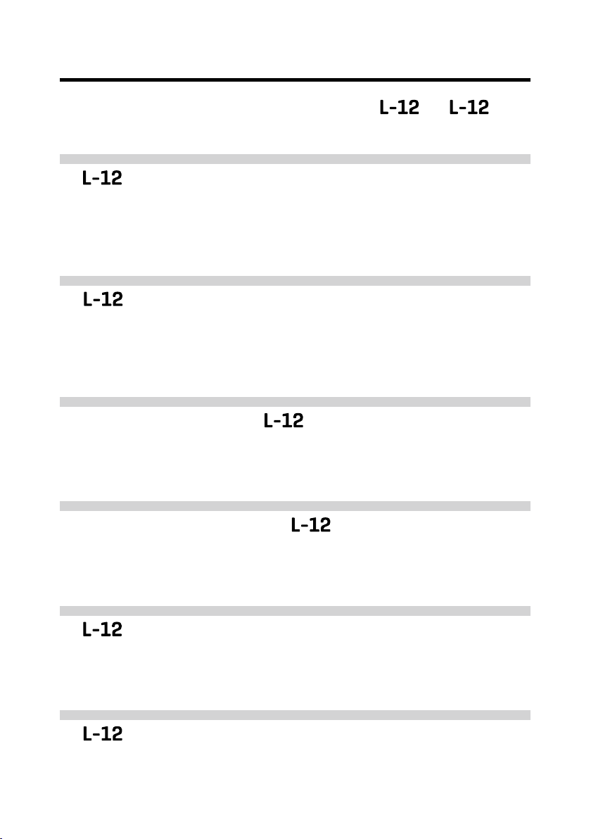
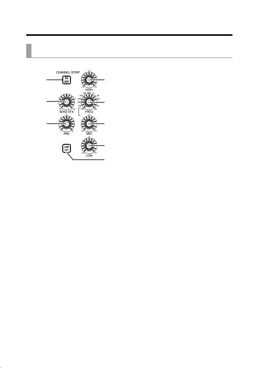
Names and functions of parts … 5
Top ………………………………… 5
Rear panel ……………………… 14
Equipment connection example 15
Live PA system ………………… 15
Display overview ……………… 17
Home Screen ………………… 17
Turning the unit on/off ………… 18
Turning the unit on …………… 18
Turning the power off ………… 20
Using the MENU screen ……… 21
Mixer ……………………………… 22
Outputting input sounds from
output devices ………………… 22
Adjusting the tone and
panning ………………………… 24
Using the built-in effects ……… 25
Using scene functions ………… 27
Setting signals output from
MONITOR OUT A–E…………… 30
Recording and playback ……… 32
Preparing to record …………… 32
Recording and playing tracks … 34
Adding marks ………………… 37
Redoing parts of recordings
(punching in/out) ……………… 38
Mixing down tracks …………… 40
Recording automatically ……… 42
Capturing audio before recording
starts …………………………… 44
Selecting the folder where projects
are saved ……………………… 45
Selecting projects for playback 46
Using the metronome ………… 47
Enabling the metronome……… 47
Changing metronome
settings ………………………… 48
Using the slate mic …………… 52
Recording with the slate mic … 52
Changing slate mic settings … 53
Projects …………………………… 55
Changing project names ……… 55
Deleting projects ……………… 57
Protecting projects …………… 58
Checking project information … 59
Saving projects to USB ash
drives …………………………… 60
Importing projects from USB ash
drives …………………………… 63
Managing marks ……………… 65
Audio les………………………… 66
Deleting audio les …………… 66
Exporting audio les to USB ash
drives …………………………… 68
Importing audio les from USB ash
drives …………………………… 70
Using audio interface functions 72
Installing the driver …………… 72
Connecting to a computer …… 73
Inputting return signals from the
computer to a stereo channel……74
Using card reader functions … 75
Recording and playback
settings …………………………… 76
Changing the recording format 76
Changing automatic recording
settings ………………………… 77

4
Introduction
Showing recording levels on level
meters ………………………… 79
Enabling latency adjustment … 79
Changing the playback mode … 80
SD card settings ………………… 81
Checking the open space on SD
cards …………………………… 81
Formatting SD cards ………… 81
Testing SD card performance … 82
Various settings ………………… 84
Setting the date and time …… 84
Setting the footswitch ………… 85
Changing the sampling rate … 86
Disabling the automatic power
saving function ………………… 87
Adjusting the display
contrast ………………………… 88
Restoring settings to factory
defaults ……………………… 88
Checking the rmware
versions.………………………… 89
Updating the rmware ……… 90
Troubleshooting ………………… 91
Specications …………………… 93
Send effects specications …… 94
Mixer block diagram …………… 95

5
Names and functions of parts
To p
Input channel section
①
②
③
④
⑤
⑥
⑦
⑧
⑨
⑩
⑪
⑫
⑬
⑮
⑭
1MIC/LINE input jack
These input jacks have built-in mic preamps. Connect mics, keyboards and guitars to them.
These can be used with both XLR and 1/4-inch (balanced or unbalanced) phone plugs.
248V switch/indicator
This turns 48V phantom power on or off. Turn this on ( ) to supply
phantom power to MIC/LINE input jacks 1–4 (or 5–8).
The indicator lights when the switch is on.
3Hi-Z switch
Use to switch the input impedance of MIC/LINE input jack 1 (or 2).
Turn it on ( ) when connecting a guitar or bass guitar.
4PAD switch
This attenuates (reduces) the input signal of the equipment connected
to the MIC/LINE input jack by 26 dB.
Turn this on ( ) when connecting line level equipment.
5SIG indicator
This indicator shows the signal level after adjustment by the GAIN knob.
The indicator color changes according to the signal level.
Lit red: −3 dB
Lit green: −48 to −3 dB
Blinking green: −55 to −48 dB
6GAIN knob
Use to adjust the input gain of the mic preamp.
The range of adjustment depends on the on/off status of the MIC/LINE
input jack switch (Hi-Z on channels 1–2 or PAD on channels 3–8).
Jack Adjustment range
MIC/LINE input jack 1–2 (XLR) +16 – +60 dB
MIC/LINE input jack 1–2 (TRS) Hi-Z off +16 – +60 dB
Hi-Z on (TS) +6 – +50 dB
MIC/LINE input jack 3–8 PAD off +16 – +60 dB
PAD on -10 – +34 dB
7COMP knob
Use to adjust the amount of compression.
8SEL button
Use to select a channel for parameter adjustment in the channel strip section.
Channels with lit SEL buttons are affected by channel strip section adjustments.
9REC/PLAY button
Use this button to switch between recording input signals to the SD
card and playing back an already recorded le from the SD card.
Status Explanation
Lit red Input signals will be recorded to the SD card after passing
through the compressor.
Lit green
An already recorded le will be played back. Playback signals are input
before the equalizer. In this state, signals from input jacks are disabled.
Unlit Files will neither be recorded nor played back.

6
Names and functions of parts
①
②
③
④
⑤
⑥
⑦
⑧
⑨
⑩
⑪
⑫
⑬
⑮
⑭
!LINE input jacks (TS)
Use these input jacks to connect line level equipment. For example,
connect keyboards or audio devices.
These can be used with 1/4-inch (unbalanced) phone plugs.
NOTE
If only the left LINE input jack (TS) channel is connected, it will be handled as
a mono channel.
"LINE input jacks (RCA)
Use these input jacks to connect line level equipment. For example,
connect audio devices.
These can be used with RCA pin connectors.
NOTE
If both the RCA and TS LINE input jacks are connected, the TS input jacks
will be used.
#USB button
This switches the signals input to channels 9/10 (or 11/12).
Lit: audio return signal output from the computer
Unlit: LINE input jacks
NOTE
Connect the to a computer as an audio interface. (→P.73)
$MUTE button
This mutes or unmutes signals sent to the master fader.
To mute the channel, press this button to light it.
This has no effect on recording to the SD card.
HINT
%Level meter
This shows the signal level after adjustment by the channel fader.
Ranges shown: -48 dB – 0 dB
NOTE
If the actual channel fader position differs from the channel fader position
recalled using the scene function, for example, the level meter will show the
recalled fader position.
&Channel fader
This adjusts the channel signal level in a range from −∞ to +10 dB.

7
Names and functions of parts
②
③
④
⑤
⑥
⑦
①
⑧
1EQ OFF button
When this button is lit, HIGH, MID, LOW and
LOW CUT are bypassed.
2HIGH knob
This adjusts the boost/cut of high-frequency
equalization.
Type: shelving
Gain range: −15 db – +15 dB
Frequency: 10 kHz
3MID FREQ knob
This adjusts the central frequency of the mid
frequency equalization.
Frequency (in Hz): 100, 140, 200, 250, 315, 500,
800, 1k, 1.3k, 2k, 3k, 5k or 8k
4MID knob
This adjusts the boost/cut of mid-frequency
equalization.
Type: peaking
Gain range: −15 db – +15 dB
Frequency: set by MID FREQ knob
5LOW knob
This adjusts the boost/cut of low-frequency
equalization.
Type: shelving
Gain range: −15 db – +15 dB
Frequency: 100Hz
6LOW CUT button
This turns on/off the high-pass lter, which cuts
low frequencies.
When ON, signals below 75 Hz are attenuated
12 dB/octave.
7SEND EFX knob
The amount that can be sent to the SEND EFX
bus can be set from −∞ to +10 dB.
8PAN knob
Use to adjust the channel volume balance and
stereo position sent to the master bus.
On a stereo input channel, this adjusts the
volume balance between the left and right chan-
nels.
CHANNEL STRIP section

8
Names and functions of parts
1MASTER and A–E buttons
These switch between the mixes output from
the MASTER OUT and MONITOR OUT A–E
jacks.
MASTER button: Use to show and adjust the
mix output from the MASTER OUT jacks.
A–E buttons: Use to show and adjust the mixes
output from the MONITOR OUT A–E jacks.
NOTE
• The parameters that can have separate settings
for the MASTER and A–E mixes are as follows.
- Fader positions (each channel)
①
FADER MODE section

9
Names and functions of parts
SCENE section
③
①
②
④
⑤
1ON button
Press this button, lighting it, to use the scene
function
2RESET button
Press this button to reset the current mixer set-
tings to the factory defaults.
31–9 buttons
Use these buttons to select the scene to use to
save the current mixer state and to load saved
scenes.
If the current mixer settings match the settings
of a scene, the corresponding number button
will light.
This unit can save up to 9 scenes.
4RECALL button
Use this button when loading scenes saved to
buttons 1–9.
When this button is pressed, buttons 1–9 will
blink if they have saved scenes and be unlit if
they do not. To recall a saved scene, press a
blinking button between 1 and 9. To cancel recall-
ing a scene, press the RECALL button again.
5SAVE button
Use this button when saving the current mixer
settings to a scene.
When this button is pressed, buttons 1–9 will
blink if they have saved scenes and be unlit if
they do not. To save a scene, press a button be-
tween 1 and 9 to save it to that number. To can-
cel saving a scene, press the SAVE button again.

10
Names and functions of parts
Send effect (SEND EFX) section
1Effect type list
This is the list of the built-in effects.
The name of the currently selected effect lights.
It blinks when being selected.
If some time passes without a different effect
being selected, the previously selected effect
will remain selected.
2TYPE knob
Use to select the built-in effect.
Turn this knob to select the effect type, and
press it to conrm.
3Parameters 1 and 2
Use these to adjust the parameters for the se-
lected effect.
See P. 95 for the parameters of each effect.
4EFX RETURN MUTE button
This mutes or unmutes the signal sent from the
built-in effect.
To mute the signal, press this button to light it.
5EFX RETURN level meters
These show the levels of the signals sent from
the built-in effect to the master bus after adjust-
ment by the EFX RETURN fader. Their range is
from −48 dB to 0 dB.
6EFX RETURN fader
This adjusts the levels of the signals sent from
the built-in effect to the master bus in a range
from −∞ dB to +10 dB.
NOTE
If the actual channel fader position differs from the
channel fader position recalled using the scene
function, for example, the level meters will show
the recalled fader position.
①
②
③
④
⑤
⑥

11
Names and functions of parts
Output section
①
②
③
④
⑤
⑥
⑩
⑦
⑧
⑪
⑫
⑬
⑨
1MASTER OUT jacks
These jacks output signals after volume adjust-
ment by the master fader.
Connect them to a power amplier, a PA system
or speakers with built-in ampliers, for example.
These support balanced output with XLR con-
nectors (2 HOT).
2MONITOR OUT A jacks
These jacks output signals after volume adjust-
ment by the MONITOR OUT A knob.
You can, for example, connect a monitoring sys-
tem for the mixer operator here.
These support balanced 1/4-inch jack phone out-
put.

12
Names and functions of parts
NOTE
The MONITOR OUT A jacks can be set to output
the same signals as the MASTER OUT jacks or the
signals set separately in the fader mode section.
(→P.30)
3MONITOR OUT A PHONES jack
This headphone jack outputs signals after volume
adjustment by the MONITOR OUT A PHONES
knob.
NOTE
The MONITOR OUT A PHONES jack always out-
puts the same signals as the MONITOR OUT A
jacks.
4MONITOR OUT B–E PHONES jacks
These headphone jacks output signals after
volume adjustments by the MONITOR OUT B–E
PHONES knobs.
NOTE
The MONITOR OUT B–E jacks can be set to output
the same signals as the MASTER OUT jacks or the
signals set separately in the fader mode section.
(→P.30)
5MONITOR OUT A knob
Use to adjust the volume of the signals output
from the MONITOR OUT A jacks.
6MONITOR OUT A PHONES knob
Use to adjust the volume of the signals output
from the MONITOR OUT A PHONES jack.
7MONITOR OUT B–E knobs
Use to adjust the volumes of the signals output
from the MONITOR OUT B–E PHONES jacks.
8MONITOR OUT A switch
This switches MONITOR OUT A output between
the L/R jacks and the PHONES jack.
Status Explanation
MASTER ( )The same signals as the
MASTER OUT are output.
A ( )The signals set in the
FADER MODE section are
output.
9MONITOR OUT B–E switches
These switch the signals output from the MONI-
TOR OUT B–E PHONES jacks.
Status Explanation
MASTER ( )The same signals as the
MASTER OUT are output.
B–E ( )The signals set in the
FADER MODE section are
output.
!MASTER REC/PLAY button
Use this button to switch between recording the
signal input on the master bus to the SD card
and playing back an already recorded file from
the SD card.
Status Explanation
Lit red The signal will be recorded to the
SD card after adjustment by the
master fader.
Lit green The playback signal of a file is in-
serted on the master bus. The REC/
PLAY buttons of other channels will
be unlit at this time.
Unlit Files will neither be recorded nor
played back.
"MASTER MUTE button
This mutes or unmutes the MASTER OUT jacks.
To mute the signals, press this button to light it.
#Master level meters
These show the signal levels output from the
MASTER OUT jacks in a range from −48 dB to 0
dB.
$Master fader
This adjusts the signal levels output from the
MASTER OUT jacks in a range from −∞ to +10
dB.
NOTE
If the actual channel fader position differs from the
channel fader position recalled using the scene
function, for example, the level meters will show
the recalled fader position.

13
Names and functions of parts
RECORDER section
1Slate mic
This is a built-in mic for recording comments.
This mic input is active while the SLATE button
is being pressed.
The input channel can be set to channels 1–12,
MASTER, or all channels. (→P. 54)
2SLATE button/indicator
This activates the slate mic.
The slate mic is activated while this button is
being pressed and its indicator is lit.
3Display
This shows the recorder status and MENU
screen.
4MENU button
This opens the menu.
5Selection encoder
Use this to change menus and values and to
move between items.
Operation Result
Turn when main re-
corder screen open
Search forward or backward
in one-second increments.
Push when main re-
corder screen open
This sets a mark.
Turn when menu
open
Move between parame-
ters and change values.
Press when menu open
Conrm parameter value.
6TEMPO button/indicator
This sets the tempo of the metronome built into
the recorder.
Press this button to make the recorder detect
the tempo from the average value.
During recording and playback, the indicator
blinks at a tempo of 40.0–250.0 bpm.
See P. 49 for metronome settings.
7STOP button
This stops the recorder.
8PLAY/PAUSE button/indicator
This starts and pauses recorder playback. The
indicator shows the playback status as follows.
Status Explanation
Lit green The recorder is playing back.
Blinking green Playback is paused.
9REC button/indicator
This puts the recorder in recording standby. The
indicator shows the recording status as follows.
Status Explanation
Lit red The recorder is recording or in
recording standby.
Blinking red Recording is paused.
!|<< button
Press to move to the previous mark.
If no mark is set, this moves to the beginning.
Press this button when at the beginning to move
to the previous project.
Press and hold to search backward. (The longer
you press, the faster the speed becomes.)
">>| button
Press to move to the next mark.
If it is the last mark, this moves to the end of the
le. Press this button again to move to the next
project.
Press and hold to search forward. (The longer
you press, the faster the speed becomes.)
#OVER DUB button/indicator
Status Explanation
Lit (ON) Record by overwriting into the
current project folder.
Unlit (OFF) Create a new project folder and
make a new recording.
①
②
③
⑨
⑫
④
⑤
⑧
⑦
⑩
⑥
⑪

14
Names and functions of parts
① ② ③ ④ ⑥ ⑦ ⑧ ⑨⑤
1POWER switch
This turns the on and off.
Switch to — to turn the power on. Switch to
to turn the power off.
When the POWER switch setting is changed to
OFF, the current mixer settings are automatically
saved in the unit and in the settings file in the
project folder on the SD card.
2DC IN 12V AC adapter connector
Connect the included AC adapter here.
3USB HOST port
This USB 2.0 HOST port is for connecting USB
ash drives.
Projects and audio files can be saved on and
loaded from connected USB ash drives.
4MODE switch
Set whether to use as a USB HOST, card reader
or audio interface.
This cannot be changed after starting up.
5USB DEVICE port
This USB 2.0 port is for connecting with a com-
puter.
It will start up as a card reader or audio interface,
depending on the MODE switch selection.
Card reader mode
Operating as an SD card reader, data can be ex-
changed with a computer.
Audio interface mode
Operating as an audio interface, audio data can
be exchanged with a computer.
Inputs: The signals from channels 1–12 after they
pass through their compressors and the master
fader output signals are input to the computer.
Outputs: Outputs from the computer can be as-
signed to channels 9/10 and 11/12.
Use when connected to an iOS device is possi-
ble if the CLASS COMPLIANT MODE switch is
set to ON.
6CLASS COMPLIANT MODE switch
Use this to turn Class Compliant Mode ON/OFF.
Set it to ON when connected to an iOS device.
7SAMPLE RATE switch
Set the sampling rate used by the unit.
This cannot be changed after starting up.
8SD card slot
This slot is for SD cards.
The supports SD, SDHC and SDXC card
specications.
You can test whether an SD card can be used with
the . (→P.82)
HINT
9CONTROL IN jack
A footswitch (ZOOM FS01) can be connected
here.
The footswitch can be assigned to one function:
starting/stopping recorder playback, manually
punching in/out or muting/unmuting the built-in
effect. (→P.85)
Rear panel

15
Equipment connection example
Live PA system
Footswitch
Headphones
Performer
headphones×4
Powered speakers
(main)
Keyboard
Drums
Drum mics ×3
Electric guitar
Vocal/chorus mics
×2
Electric
acoustic guitar
Bass
Portable audio player
Computer
(for recording and
playback)
DI

16
Equipment connection example
Footswitch
Headphones
Performer
headphones×4
Powered speakers
(main)
Keyboard
Drums
Drum mics ×3
Electric guitar
Vocal/chorus mics
×2
Electric
acoustic guitar
Bass
Portable audio player
Computer
(for recording and
playback)
DI

17
Display overview
①
⑨ ⑩
⑤⑥ ⑧⑦
⑫
⑬
⑭
④
②
③
⑪
No. Item Explanation
1Project name This shows the project name.
"<" appears if there is another project before this one in the
folder.
">" appears if there is another project after this one in the folder.
2Status icon This shows the status as follows.
: Stopped
: Paused
: Recording
: Playing back
3Counter This shows the hour: minute: second.
4Progress bar This bar shows the amount of time in the project from begin-
ning to end.
5Folder name The folder where the project is saved will be shown as FOLD-
ER01 – FOLDER10.
6
7Metronome icon This is shown when the metronome is enabled. (→P. 47)
8Project protection icon This is shown when project protection is enabled.(→P.58)
9Remaining recordable
time
This shows the remaining recordable time.
This will change automatically according to the number of chan-
nels that have recording enabled with .
!Recording le format This shows the recording le format used by the recorder.
"Current date and time This shows the current date and time.
#SD card icon This is shown when an SD card is being recognized.
$Mark This shows the mark number and the status as follows.
: at mark (mark added at counter location)
: not at mark (mark not added at counter location)
%
Longest le time in project
This shows the length of the longest le in the project.
Home Screen

18
Turning the unit on/off
POWER
switch DC IN 12V
AC adapter connector
GAIN knob
Input/Output
jacks
Master faderChannel faders
EFX RETURN fader
1. Conrm that the output devices connected to the are turned off.
Turning the unit on

19
Turning the unit on/off
2. Conrm that is set to OFF.
3. Plug the AD-19 adapter designed for this unit into an outlet.
4. Set all knobs and faders to their minimum values.
5. Connect instruments, mics, speakers and other equipment.
See P.15 for connection examples.
HINT
6. Set to ON.
7. Turn on the output devices connected to the .
NOTE
• When using a passive guitar or bass guitar, connect it to channel 1 or 2, and turn on. (→P.5)
• When using a condenser mic, turn on. (→P.5)
• The power will automatically turn off if the is unused for 10 hours. If you want the power to stay
on always, disable the automatic power saving function (→P.87)

20
Turning the unit on/off
Turning the power off
1. Minimize the volume of devices connected to the .
2. Turn off the power of output devices connected to the .
3. Set to OFF.
The following screens appear and the power turns off.
NOTE
When the power is turned off, the current mixer settings are saved in the project on the SD card. If they can-
not be saved to the SD card, they will be saved in the unit.
Other manuals for LiveTrak L-12
1
Table of contents
Other Zoom Mixer manuals
Popular Mixer manuals by other brands

Behringer
Behringer EUROPOWER PMP518M user manual

Marshalltown
Marshalltown 300DD owner's manual

KitchenAid
KitchenAid 4KSMC50S Instructions and recipes

A/S WODSCHOW & CO
A/S WODSCHOW & CO AR30 operating instructions

Felisatti
Felisatti MF800VE operating instructions

KitchenAid
KitchenAid 5KSM7990XEWH Original instructions