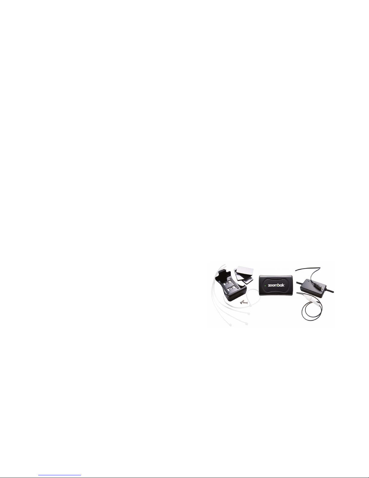
Step 2 – Mount Device
Your installation kit includes a device mounting bracket to provide
for secure installation as well as the ability to remove the device for
portable use. Zoombak recommends the use of Velcro set or 2 sided
tape for installation of device bracket. Use of mounting bracket is
optional; the Zoombak locator can be mounted directly using supplied
Velcro, 2 sided tape and zip ties.
zoombak.com
6
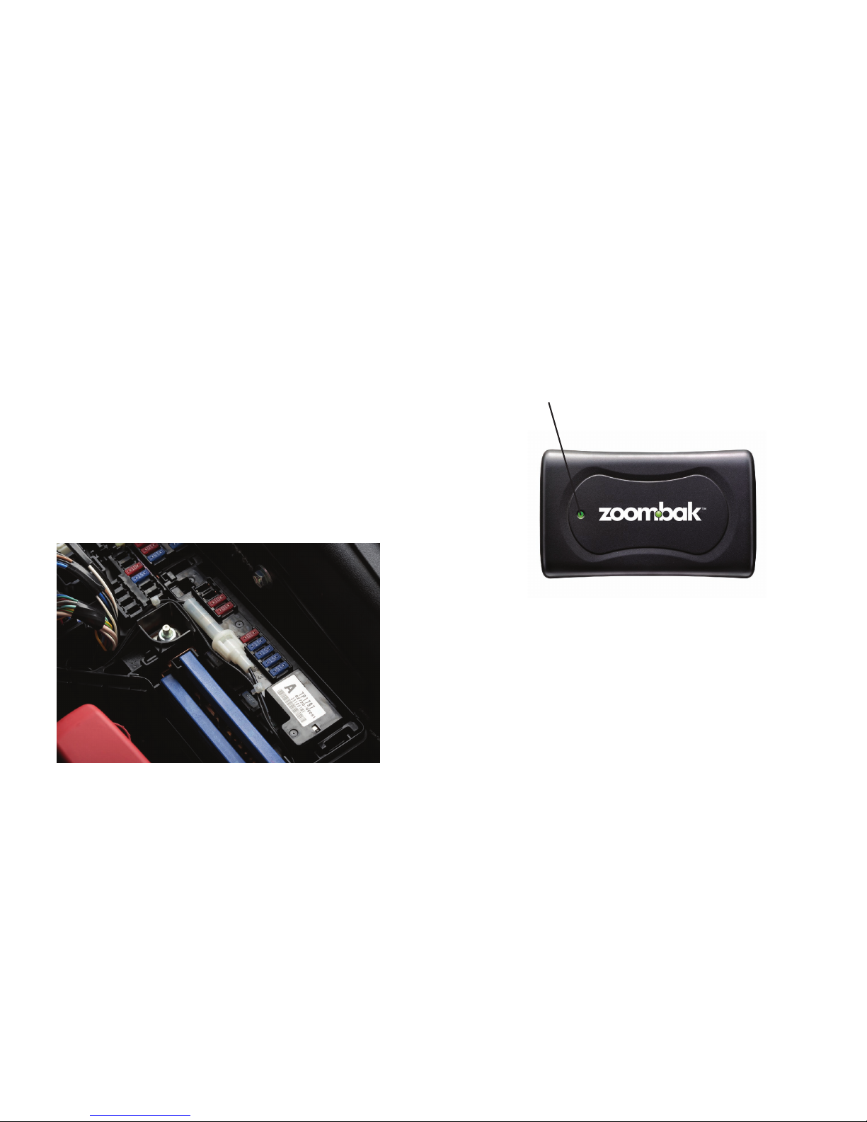
Step 3 – Mount Device Charger
The device charger should be securely attached to the vehicle, close
to the device attachment, using the four mounting holes. The device
charger can be securely attached using the included Velcro or the
included zip ties.
Step 4 - Connect Power Harness
USE CAUTION WHEN PROBING WIRES IN THE VEHICLE.
AVOID HARNESS GOING INTO AND AROUND THE AIRBAG MODULES.
AVOID ANY HARNESS TAPED IN YELLOW OR BEARING YELLOW
“SRS” (SUPPLEMENTAL RESTRAINT SYSTEM) TAGS.
Use wire ties to secure wiring from being pulled out of the Zoombak
Locator and to insure that it does not interfere with any vehicle
components.
Black Wire (-) ground wire
Once the Zoombak Locator Power Supply module is mounted, connect
the black ground wire to an existing factory bolt using crimp-on ring
connector. Please note: the power wire is also black, however, it has
a dotted white line with the white plastic fuse holder attached to it.
This connection should be made rst. Use a wire brush or rotary le
to remove the paint from around the bolt to allow for the best possible
connection to ground. A good location to nd a suitable bolt is in
either the drivers or passengers kick panel. Do not select a bolt that
has an existing factory ground wires attached to it. Make sure the bolt
is retightened properly after you are nished. Make sure any paint
underneath the bolt has been removed to provide the best possible
ground connection. Once the vehicle is reassembled this connection
should not be immediately visible.
Red (12v+) positive supply wire
Once the ground connection has been completed, locate a source of
positive (+) 12 volts that remains constant regardless of whether the
zoombak.com 7