Zorg 9001 User manual

Commercial Vehicle Blind
Spot Detection System
9001
Installation Guide
User Guide

IMPORTANT
READ BEFORE PROCEEDING
Table of Contents
1
System overview
2
What’s in the box
3
Wiring schematic
4
Installing the Radar sensor
5
Installing the Blind Spot Indicator
6
Buzzer Installation
7
Attaching the GPS receiver
8
Mounting the control box
9
Wiring
10
System Self-Test
11
Technical Specications
12
Dip Switch Settings
Page
1
1
2
3
4
5
6
6
7
7
8
8
The Zorg Blind Spot Detection System should only be installed by a qualified or
suitably competent and experienced automotive technician.
The steps outlined herein are only a guide to assist in installing the system. It is
assumed that the technician has sufficient knowledge in the dismantling/reassembly of
the vehicle, the wiring, and installing automotive electrical components. In addition, the
technician is responsible for ensuring that the Blind Spot Detection system is installed
correctly and tested to ensure proper operation.
Note: The Blind spot detection system does not prevent contact with other vehicles.
The
system is only an aid in detecting possible objects within the blind spot of the
vehicle.
The driver has the final reasonability to ensure that there is nothing in the
vehicle's
path when changing lanes or turning. This device does not eliminate the need
for
mirrors or good driving practices.
WARNING:
The system may not operate properly during severe weather conditions,
for example, snow, ice, heavy rain, dirt, and mud. Always drive responsibly with due
care and
attention. Failure to take care may result in a crash.

1
System Overview
What’s in the box
2
Radar Sensor Sensor Mounting Bracket Control Box GPS Receiver
Main Harness Blind Spot Indicator LED Sensor Extension Cable Buzzer
Installation Kit
Cable Ties
Velcro
Control Box Bracket - 2 pcs
Bolts M6*16 - 4 pcs
Screws ST8*30 - 2 pcs
Buzzer Extension
Cable
1
Blind Spot Indicator Mounting Kit
LED Housing
LED Housing Back Plate
Double-sided Tape
Screw 3*12 - 1pc
14mm (9/16") Hole Saw
*Parts shown are for reference only and may be different or changed or deleted based upon application
To reduce the risk of collisions with objects in the truck's
blind spot, the Blind Spot Radar monitors the area along the
vehicle's left or right side (depending upon installation). It
will warn the driver with visual and audible alerts to objects
in the detection zone.
The system consists of the Radar sensor mounted to the
side of the vehicle, the Blind Spot LED Indicator
install on
the
side A-pillar matching the side that the Radar sensor is
mounted on for visual alerts, plus a buzzer installed under
the dash, which delivers audible warnings.
The truck’s driving speed is obtained via an installed GPS receiver and has
two operational modes -
low-speed urban mode with Turn-Assist below 20 Mph
/ 30km/h and normal
driving mode above 20 Mph / 30km/h.

Wiring Schematic
3
2
LED Indicator
Warning Buzzer
Red
Black
Green
Gray
White
Blue
Blind Spot Sensor
Wiring:
Red - Ignition/ACC 9-36 Vdc+
Black - Ground Vdc-
Gray - Right Turn Signal In (+)
White - Left Turn Signal In (+)
Blue - Dimmer Input from Headlamp (+)
Green - Output Trigger 12 Vdc+ (pulsed .05amp max)
2 Amp Fuse ONLY
GPS
Antenna

IMPORTANT
To ensure optimum detection performance, the radar sensor must be installed
within the following tolerences:
Installing the Radar Sensor
4
3
1: The face of the sensor must be parallel with the truck body.
2: The face of the sensor must be perpendicular to the ground (90°)
3: The center of the sensor should be 40" (100cm) +/- 10% from the ground
4: Mount the Sensor behind the front door / mid way on the vehicle
40" / 100CM
The sensor must be mounted with
the arrow pointing upward as shown.
1: Use the Sensor Bracket to find a location that is suitable. The face of the sensor
should be flush with the vehicle if possible. The sensor should not be blocked by
object such as body panels. keep the sensor straight in line with the vehicle, and
must be at a 90 degree angle from the ground.
2: Using the bracket mark the mounting hole locations
3: After double checking to ensure there is nothing blocked by the sensor or
behind where you will be drillling, drill two holes for the mounting screws (Not Supplied).
4: Mount the Sensor to the bracket using the supplied 4 x M6*16 screws,
5: Connect the wire harness and then mount the sensor bracket to the vehicle.
Ensure the Radar sensor orientation is correct - Arrow facing upwards.
Use supplied 4xM6*16 Screws

Installing the Radar Sensor Cont.
4
4
The Sensor extension wire must be run into the vehicle interior. Find a suitable
route for the cable where it will not interfere with any other vehicle system,
safety device, or engine component such as the exhaust pipe.
1: Route the cable into the vehicle and seal the entry point to ensure no water will
enter the vehicle.
2: Find a good location for the control module. The module needs be secure and
safe from any moving item, possibility of damage, or extreme heat.
3: Route the sensor extension cable to the location for the module.
*** Before making any electrical connections to the vehicle
disconnect the Negative battery terminal***
5Installing the Blind Spot Indicator
The warning indicator should be mounted in a location that is directly in the
line-of-site of the driver when checking the side mirror of the side of the vehicle
that the sensor is mounted on. The recommended location is on the A-pillar. DO
NOT INSTALL OVER A AIR-BAG OR OTHER SAFETY DEVICE. The Indicator
can be surface mounted or mounted to the dash in the supplied housing.
Option 1: Flush mount
1. Remove the plastic trim panel from the A-pillar, inspect behind it for wires
or an air-bag. DO NOT INSTALL IN FRONT OF A AIR-BAG!
2. Mark the desired location and drill a 14mm hole in the A-pillar trim using the
supplied hole saw.
3. Insert the cable into the hole and run it down the inside of the trim.
4. Press the Blind Spot Indicator into the hole.
5. Route the indicator wire to the control box location.

Installing the Blind Spot Indicator cont.
5
5
Option 2: Surface Mounting
1: The Surface mount option can be used on the A-pillar or the top of the dash-
board in front of the A-pillar.
2: Use the supplied double sided tape and mounting screw. Always double check
behind any surface that you will screw into before securing the housing.
3: Attach the base plate to the desired location.
4: Insert the LED indicator into the surface mount housing cover, snap in place.
5: Route the wire out of the back of the housing and snap the housing into place
over the base plate.
6: Route the wire to the control box and connect.
6Buzzer Installation
The warning buzzer should be located in the footwell of the vehicle on the side
that the blind spot sensor is located. It must not be blocked behind a panel or
inside the dash board as the driver may not be able to hear the warning tone.
1: Determine the mounting location.
2: Use the supplied double sided tape and / or two screws to mount the buzzer
securly.
3: Route the buzzer wire to the control box and connect.

Attaching the GPS Receiver
7
8
GPS
6
The GPS Receiver Antenna provides data to the control box and selects the mode
based on the vehicle speed. The Antenna MUST have a clear view of the sky in
order to operate correctly. If the signal is lost due to a tunnel or other obstruction
the system will still function but only in driving speed mode.
1: The antenna should be attached to the windshield on the inside at the lower
corner behind the A-pillar.
2: Clean the glass where the antenna will be mounted using an alcohol pad to
ensure a proper contact and bond can be made when attaching the antenna.
3: We recommend using a adhesive promoter such as 3M brand 4298 (not included)
to ensure a lasting bond and application.
4: Using the supplied double sided tape attach the antenna to the glass. Press
firmly for 30 seconds to allow the tape to bond.
5: Route the wire from the antenna to the control box and connect.
*** Before making any electrical connections to the vehicle
disconnect the Negative battery terminal***
Do not connect the wire harness to the control box until all vehicle connections
are made. The Sensor, Buzzer, GPS Antenna, and LED indicator should
already be connected to the box at this time.
With the wire harness located at the control box you will route the listed wires to
proper vehicle connection. Each vehicle is different, refer to the vehicle service
manual for proper location to connect to as needed.
Refer to the wiring schematic on page 2 if needed.
Wiring
Wiring

9
Mounting The Control Box
10
Setting The Dip Switches
1: Connect the Red wire to Ignition/ACC 9-36 (Vdc+)
2: Connect the Black wire to a vehicle Ground (Vdc-)
3: Connect the Gray wire to the Right Turn Signal Indicator (+)
4: Connect the White wire to the Left Turn Signal Indicator (+)
5: Connect the Blue wire to a positive source when the headlamps are turned on (+)
6: Connect the Green wire if required - 12Vdc+ Output Trigger (pulsed output - same
as the LED Indicator) Max 0.5amps out.
7: Connect the wire harness to the module.
8Wiring Continued
SWITCH # STATUS DEFINITION
1OFF Enable audible alert at speed below 20Mph / 30km/h DEFAULT
ON Disable audible alert at speed below 20Mph / 30km/h
2OFF System is always active DEFAULT
ON System is only active at speed below 20Mph / 30km/h
3OFF n/a
ON n/a
4OFF Radar is mounted to the LEFT side of the vehicle DEFAULT
ON Radar is mounted to the RIGHT side of the vehicle
The DIP Switches on the Control Box set the operational mode of the system.
Adjust as needed for your installation.
After the DIP Switches are set to meet your installation needs mount the control
box to a metal surface using the included double sided tape and brackets.
Clean the mounting surface with alcohol and use the adhesive promoter for the
best result.
Using the included wire ties, secure the wire harness so it cannot be pulled
out of the control box or become tangled or damaged.
7

Technical Specications
12
Slow >20Mph / 30KpmStandard <20Mph / 30Kph
Operating Voltage (V) 9 - 36v
Operating Current (mA) <300mA @ 12V
Operating Temperature (°C) -40°C ~ 80°C
Storage Temperature (°C) -40°C ~ 85°C
Operating Frequency (GHz) 77GHz - 81GHz
Transmission Power (dBM) 39.79 dBm
Modulation Mode FMCW
Antenna Type 2TX, 4RX
FOV Angle (vertical) (°)30°
FOV Angle (horizontal) (°)150°
Angle Accuracy (
°)± 0.5°
Speed Measurement Range (Mph-km/h) -120km/h ~ +120km/h -30km/h ~ +30km/h
Speed Resolution (km/h) 0.94km/h 0.46km/h
Speed Accuracy (Mph - km/h) ± 0.47km/h ± 0.23km/h
Distance Resolution (m) 0.36m 0.04m
Distance Accuracy (m) ±0.18m ±0.02m
Angle Resolution (°)30°15°
Detection Distance (m) 12m 10m
8
For More Information contact Zorg at:
Australia / Asia / Europe -
www.zorgindustries.net
North America - www.zorg-na.com
All rights reserved Zorg Industries 9/2022
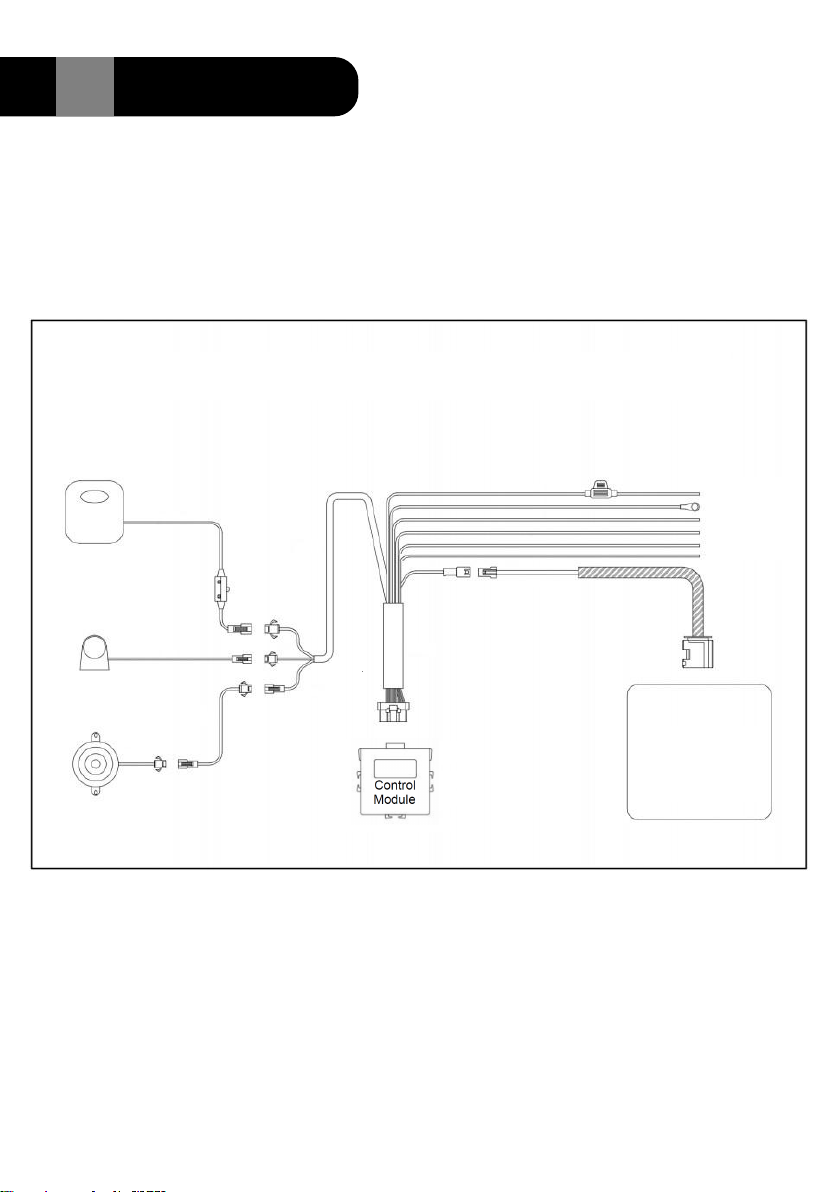
The 9001 Blind Spot system will run a self diagnostic test every time the vehicle
is started.
In a normal operational situation the LED Indicator will turn on and remain on for
two seconds, then turn off. This confirms proper operation.
If the LED Does not light at start up check the system fuse, if blown replace with a
2 amp fuse.
If trouble is detected the LED Indicator will flash when first turned on.
Five flashes indicates that there is a problem with the Radar Sensor or the
Wiring.
Fifteen flashes indicates there is a problem with the GPS Antenna
11 System Self-Test
-75Mph ~ + 75Mph -20Mph ~ + 20Mph
± 0.29 Mph ± 0.14 Mph

9001
Commercial Vehicle Blind
Spot Detection System
User Guide
The Zorg Blind Spot Radar is mounted to the side of the vehicle and incorporates
advanced microwave technology that aids in the detection of objects alongside the
truck including: All types of vehicles, Motorcycles, Cyclists, Pedestrians
Road infrastructures such as poles,barriers, and guard rails.
Advanced algorithms are able to identify whether an object is
stationary or moving,including its speed and distance from the truck.
The Blind Spot Indicator is typically installed at the A-pillar in direct
line of sight when checking the side mirror. When the Blind Spot
system senses an object in the detection zone, the Blind Spot LED
Indicator will illuminate and remain illuminated until the detection zone
is clear. In addition, if the vehicle’s turn signal indicator is activated,
the Blind Spot LED Indicator will flash and sound a alert tone. (no tone
will sound if the turn signal is not activated).
1
The 9001 Blind Spot Detection System performs a self test each time the vehicle
is started to ensure proper operation. When turning the ignition on the LED indicator
will light solid for 2 seconds and shut off, this is indicating proper operation. If the
LED Indicator flashes this indicates that there is a problem and the system
is not operating properly. Do not rely on the system if this happens and contact
the installing dealer for service as soon as possible.
The Blind spot detection system does not prevent contact with other vehicles. It
does not detect parked vehicles, pedestrians, animals, or other infrastructure. The
system is only an aid in detecting possible objects within the blind spot of the vehicle.
The driver has the final reasonability to ensure that there is nothing in the vehicle's
path when changing lanes or turning. This device does not eliminate the need for
mirrors or good driving practices.
WARNING: The system may not operate properly during severe weather conditions,
for example, snow, ice, heavy rain, dirt, and mud. Always drive responsibly with due
care and attention. Failure to take care may result in a crash.

12m
150º
3m
1.5m
IMPORTANT
The system calculates driving speed via a GPS receiver
attached to the windshield. Do not cover or block the GPS
receiver. If GPS signal is unavailable, such as when in a
tunnel or other obstruction the system will still operate but in
driving mode only, as for speed above 20Mph / 30Km/h.
S
S
p
p
e
e
e
e
d
d
D
D
e
e
t
t
e
e
c
c
t
t
i
i
o
o
n
n
Z
Z
o
o
n
n
e
e
W
W
h
h
a
a
t
t
'
'
s
s
d
d
e
e
t
t
e
e
c
c
t
t
e
e
d
d
O
O
j
j
e
e
c
c
t
t
i
i
n
n
D
D
e
e
t
t
e
e
c
c
t
t
i
i
o
o
n
n
Z
Z
o
o
n
n
e
e
?
?
T
T
r
r
u
u
c
c
k
k
'
'
s
s
T
T
u
u
r
r
n
n
S
S
i
i
g
g
n
n
a
a
l
l
I
I
n
n
d
d
i
i
c
c
a
a
t
t
o
o
r
r
B
B
l
l
i
i
n
n
d
d
S
S
p
p
o
o
t
t
I
I
n
n
d
d
i
i
c
c
a
a
t
t
o
o
r
r
B
B
l
l
i
i
n
n
d
d
S
S
p
p
o
o
t
t
A
A
u
u
d
d
i
i
b
b
l
l
e
e
A
A
l
l
e
e
r
r
t
t
OFF
OFF
NO
ON
OFF
NO
OFF
ON
NO
ON
FLASH
YES
OFF
OFF
NO
ON
OFF
NO
OFF
ON
NO
ON
FLASH
YES
NO
YES
Above
30km/h
3m x 12m
Moving objects only
NO
YES
Below
20 Mph
30km/h
1.5m x 3m
All objects. Stationary
& moving. Includes
pedestrians and
cyclists
At speeds above 20Mph / 30
Km/h, the detection zone will
extend to 3m (9ft) into the
adjacent lane and up to 12m
(36 feet) alongside the truck.
In this mode, the Blind Spot
system focuses on detecting
moving objects like vehicles,
motorcycles, and cyclists. It
will ignore stationary objects
such as parked cars, guard
rails, and poles to minimize
false alerts.
At speeds below 20Mph / 30Km/h, the blind spot
system Turn-Assist mode activates. The detection
zone is reduced to 3m (9ft) by 1.5m (4.5ft) and will
alert the driver to both moving and stationary objects.
This mode is beneficial when turning at intersections
or maneuvering in tight areas. In addition, the system
can detect pedestrians, cyclists, and other objects in
the Blind Spot area.
20 Mph
wayNote: The system can be deactivated by turning on the emergency 4- will notflashers of the vehicle. If driving with the 4 way flashers on the system
be operational.
2

FCC Warning
This device complies with part 15 of the FCC Rules. Operation is subject to the following two
conditions: (1) This device may not cause harmful interference, and (2) this device must
accept any interference received, including interference that may cause undesired operation.
Any changes or modifications not expressly approved by the party responsible for compliance
could void the user's authority to operate the equipment.
This equipment has been tested and found to comply with the limits for a Class B digital device,
pursuant to part 15 of the FCC Rules. These limits are designed to provide reasonable protection
against harmful interference in a residential installation. This equipment generates, uses and can
radiate radio frequency energy and, if not installed and used in accordance with the instructions,
may cause harmful interference to radio communications. However, there is no guarantee that
interference will not occur in a particular installation. If this equipment does cause harmful
interference to radio or television reception, which can be determined by turning the equipment
off and on, the user is encouraged to try to correct the interference by one or more of the
following measures:
— Reorient or relocate the receiving antenna.
— Increase the separation between the equipment and receiver.
— Connect the equipment into an outlet on a circuit different from that to which the receiver is
connected.
— Consult the dealer or an experienced radio/TV technician for help.
FCC Radiation Exposure Statement
This equipment complies with FCC radiation exposure limits set forth for an uncontrolled
environment . This transmitter must not be co-located or operating in conjunction with any other
antenna or transmitter. This equipment should be installed and operated with minimum distance
30cm between the radiator& your body.
Table of contents
Other Zorg Automobile Accessories manuals