Luftwaffe Nachtjager, HEINKEL He219 A-0 Uhu
ドイツ空軍夜間戦闘機・ハインケル He 219 A-0 ウーフー
Luftwaffe Nachtjager
HEINKEL He 219 A-0 Uhu
He 219は、第二次世界大戦においてドイツ空軍が大戦末期に保有した最高性能の
レシプロ夜間戦闘機である。
ドイツの都市部に対する夜間無差別爆撃を敢行したイギリス空軍爆撃機群に対抗
して、1940年6月ドイツ空軍に夜戦航空団が発足した。このとき迎撃にあたる夜
間戦闘機の主力機として採用されたのはBf 110である。しかし設計が古いBf 110
の性能では激化する戦局に対抗できなかった。そして、その能力不足が事実とし
て露呈し始めるのに時間はかからなかった。
そんな中、1943年に原型1号機He 219 V1が完成。双発戦闘機としては、かなり
の大型機である同機は、最高速度615km/hを有していた。これはBf 110 Eよりも
70km/h、Ju 88 C-6より120km/hも速いという素晴らしいものだった。1943年
3月25日にレヒリンの実験センターにおいて行われた模擬空戦では、Do 217 Nや
Ju 88 Rを相手に圧勝を収め、空軍上層部も300機の量産発注に同意するに至って
いる。
1943年6月1日の夜、第一夜間戦闘航空団(NJG1)に4機の先行生産型He219A-
0が配備された。その中の1機はデュッセルドルフ爆撃に飛来した783機のイギリ
ス空軍爆撃隊を迎撃するため、第一飛行隊の司令官ヴェルナー・シュトライプ少
佐の操縦によって、オランダのフェンロー基地から出撃し、5機のランカスターを
撃墜して華々しい初陣を飾ることとなる。その後も夜間戦闘機部隊の天敵であっ
たデ・ハビランドモスキートを撃墜するなど、その高性能ぶりを示したのであった。
しかし、ハインケル社の報告書によると完成したHe 219はわずか268機といわれ
ている。
SWSではこの不遇の名機の魅力を余すことなくキット化。流線型の機首、前方に
突き出したリヒテンシュタインアンテナ、射出座席、前輪式降着装置、胴体下面
に集中配置された射撃兵装や斜め銃など、夜間戦闘機として本機に求められた最
高性能をキット工作から感じ取ってほしい。
The He 219 is a high-performance reciprocating engine fighter aircraft that was
deployed by Luftwaffe in the dying hours of World War II.
To counter the indiscriminate night bombing of German urban areas by the
British Royal Air Force, Luftwaffe established a night fighter wing in June 1940.
At the time, the Bf 110 was Germany's principal night fighter deployed on
interceptions. However, the Bf 110's outdated design was incapable of
countering the intensifying war conditions. It was not long before the truth of
its inability began to be exposed.
Under such conditions, the first prototype He 219 V1 fighter was completed in
1943. It was a twin engine fighter, and a rather large one at that, with a top
speed of 615 km/h. That was an amazing accomplishment, being 70 km/h
faster than the Bf 110 E, and 120 km/h faster than the Ju 88 C-6. On March 25,
1943, it achieved a complete victory over the Do 217 N and Ju 88 R during a
dogfight simulation conducted at the testing ground in Rechlin, resulting in an
approval from the top brass of Luftwaffe for a production order of 300 planes.
On the night of June 1, 1943, four He 219 A-0 pre-production fighters were
deployed to Nachtjagdgeschwader 1 (NJG 1). In order to intercept the 783
British RAF fighters that flew into Germany to bomb Dusseldorf, one of those
prototypes was flown by NJG 1 wing commander Werner Streib out of Venlo air
base in Holland in a brilliant first campaign, shooting down five Lancaster
bombers. After that, it distinguished itself with great performances such as
shooting down the natural enemy of the night fighter wing, the de Havilland
Mosquito. However, production information by Heinkel reports that the
number of completed He 219s comprises a mere 286 planes.
This obscure high-performance aircraft has been recreated as an SWS kit that
fully showcases its appeal in unsparing detail. From the streamlined nose to the
front-protruding Lichtenstein radar arrays, the ejection seats, the tricycle landing
gear configuration, and the cannons centralized on the fuselage underside in
addition to the Schrage Musik cannons, we hope that you will be able to
perceive this aircraft's high capability for night Fighter when you build the kit.
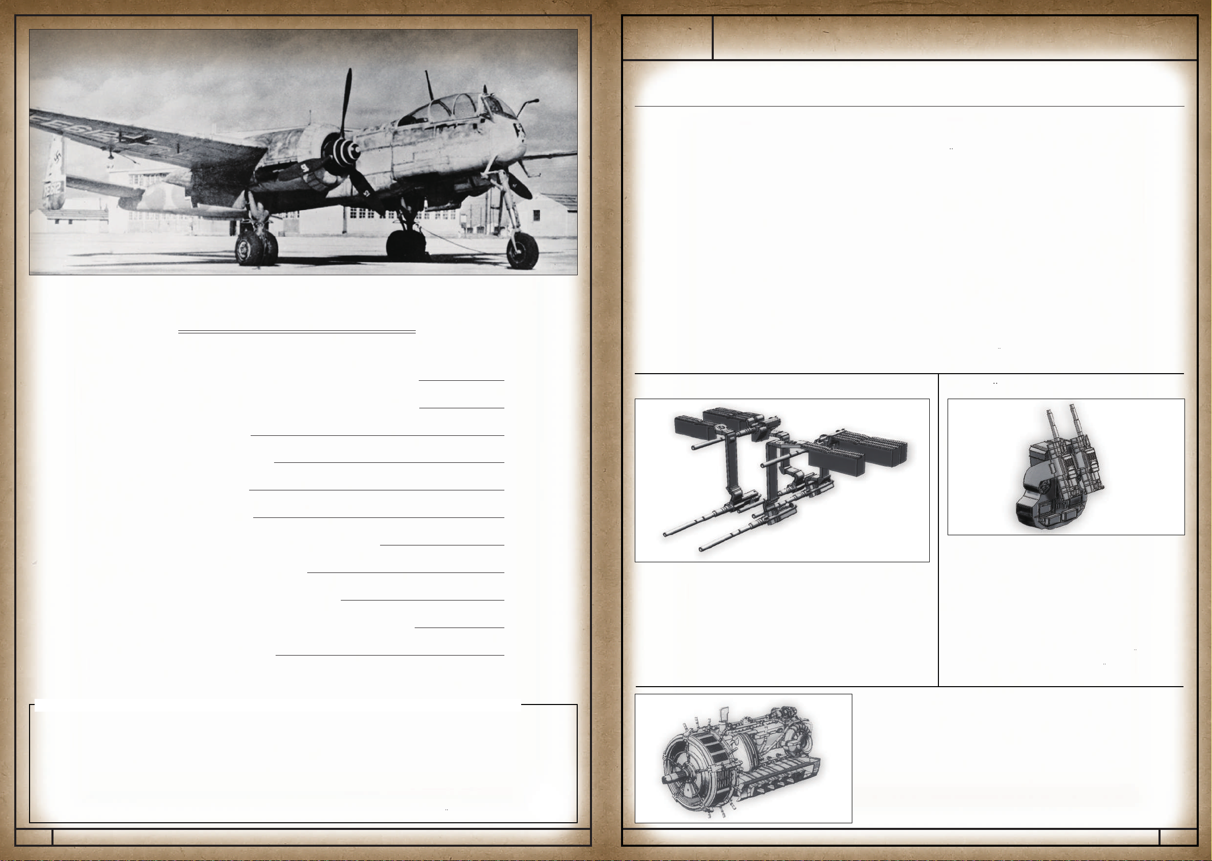
MK 108はラインメタル社が開発した30mm機関砲で、その強力な破
壊力は連合軍爆撃機の搭乗員を恐れさせた。He 219では後部胴体内
に斜め上前方を狙う角度で2門搭載している。
通称「シュレーゲ・ムジーク」と呼ばるこの搭載法は、相当の戦果を
挙げている。1943・1944年のイギリス軍爆撃機の損失の80%はこ
の斜め銃によるものと云われているほどである。装弾数は各100発ず
つで計200発。
● Schrage Musik (MK 108×2)
● Daimler-Benz DB 603A Engine
・用途:夜間戦闘機 ・乗員:2名
・全幅:18,500mm ・全長:15,540mm(機首アンテナ含まず)
・全高(水平時):4,400mm
・動力:ダイムラー・ベンツDB 603A
液冷倒立V型12気筒1,800 hp (1,324 kW) × 2
・最大速度/高度:615km/h/6,500m
・固定武装:20mmMG 151機関銃 × 2 (主翼)
20mmMG 151機関銃 × 4 (機体腹部)
30mmMK 108機関砲 × 2 (シュレーゲ・ムジーク)
● Wing Guns and Fuselage Guns
He 219は胴体下面に、目的に応じて搭載銃を変更可能な兵装パックを装備している。
想定されていたのは「MG151/20×4」「MK108×4」「MK103×4」の3種の基本
バリエーションで、それらは主翼内の固定兵装「MG151/20×2」と合わせるかたち
で「M1」「M2」「M3」と呼称されていた。ただし、実戦では武装パック内の機銃
(機関砲)を4挺(門)から2挺(門)に減らして搭載された例もあり、実際の搭載バ
リエーションは多岐にわたる。SWSでは「M1」タイプの兵装を再現している。
On the underside of the He 219's fuselage was a gun pack that allowed the cannons to be
changed depending on the objective. It is assumed that the three basic variations were "MG
151/20 × 4," "MK 108 × 4," and "MK 103 × 4," designated "M1," "M2," and M3," and
designed to coordinate with the "MG 151 × 2" fixed cannons inside the main wings.
However, in actuality, there were cases where the cannons (machine guns) inside the gun
pack were decreased in number from four to two, greatly increasing the actual number of
variations. The "M1" type of gun pack has been recreated for the SWS kit.
He 219 A-0 Uhu 実機性能諸元
●He 219 A-0 Uhu Actual Aircraft Dimensions, Performance and Characteristics
The MK 108 is a 30mm autocannon developed by Rheinmetall-Borsig,
and its strong destructive power was feared by Allied bombing crews.
Two MK 108s are mounted inside the rear fuselage of the He 219 at an
upward diagonal angle.
This upward-firing installation was commonly called "Schrage Musik," and
bore considerable fruit in battle. The 80% losses undertaken by British
bombers in 1943-44 are often attributed to Schrage Musik. Each cannon
was loaded with 100 rounds, for a total of 200 rounds.
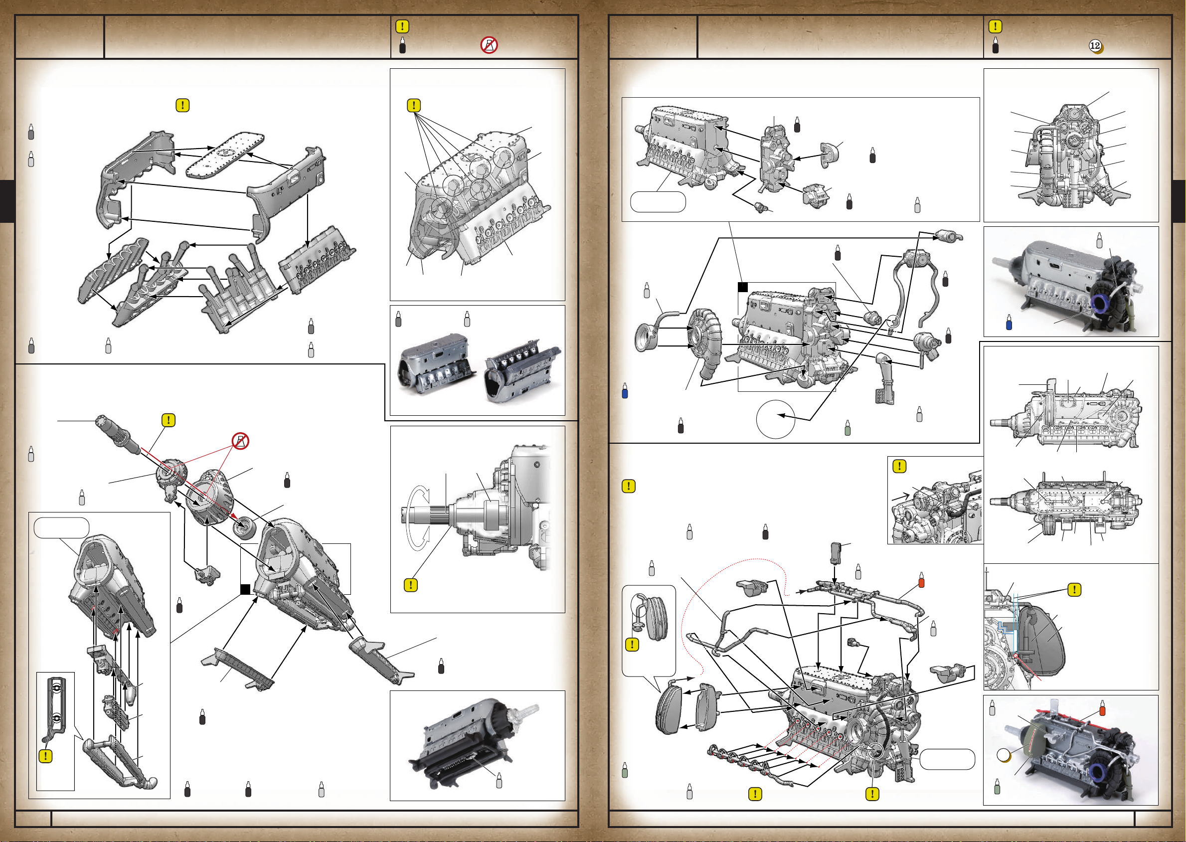
DB 603はダイムラー・ベンツ社製、液冷倒立V型12気筒エンジンである。
設計の基となったDB 601エンジンは燃料直接噴射ポンプの搭載やプロペラ軸に機銃が通せる
構造、無段変速の過給機、ローラーベアリングの多用など、高度で複雑な機構を多数採用して
いる。これらの要素は製造を困難にする要素でもあったが、同社の高度な工作技術で克服、大
戦前半にはライバル機に対する優位を保った。排気量は44,510cc、離昇出力は1,750hp/
2,450rpmとなっている。
The DB 603 was a liquid-cooled, inverted V12 engine made by Daimler-Benz AG.
The basis of the design was a DB 601 engine which was modified to include a great many advanced
and complex mechanisms, such as a direct fuel injection pump, a mechanism by which a cannon
could fire through the propeller shaft, and a centrifugal supercharger, as well as heavy use of roller
bearings. Manufacturing was difficult for several of these components, but these problems were
overcome by the company's advanced production technology, which allowed them to maintain their
superiority over rival planes during the first half of World War II. The engine had a displacement of
44,510cc as well as a power output of 1,750hp/2,450rpm at takeoff.
・Role :Night fighter ・Crew: 2
・Wingspan: 18,500mm ・Length: 15,540mm(Without Nose Antenna)
・Height (when level): 4,400mm
・Power: Daimler-Benz DB 603A
Liquid-cooled, inverted V12 with 1,800 hp (1,324 kW) × 2
・Maximum speed/altitude: 615km/h / 6,500m
・Armament: 20mm MG 151 Machine Guns × 2 (Main Wings)
20mm MG 151 Machine Guns × 4 (Fuselage Underside)
30mm MK 108 Cannons × 2 (Schrage Musik)
※写真は、キットのHe 219 A-0型ではなくA-2型となります。
Photograph shown is of the He 219 A-0 type, not the A-2 type.
Contents/目次
Inhaltsverzeichnis
Eigentliches Flugzeug
Montage-Informationen
-1. Motor
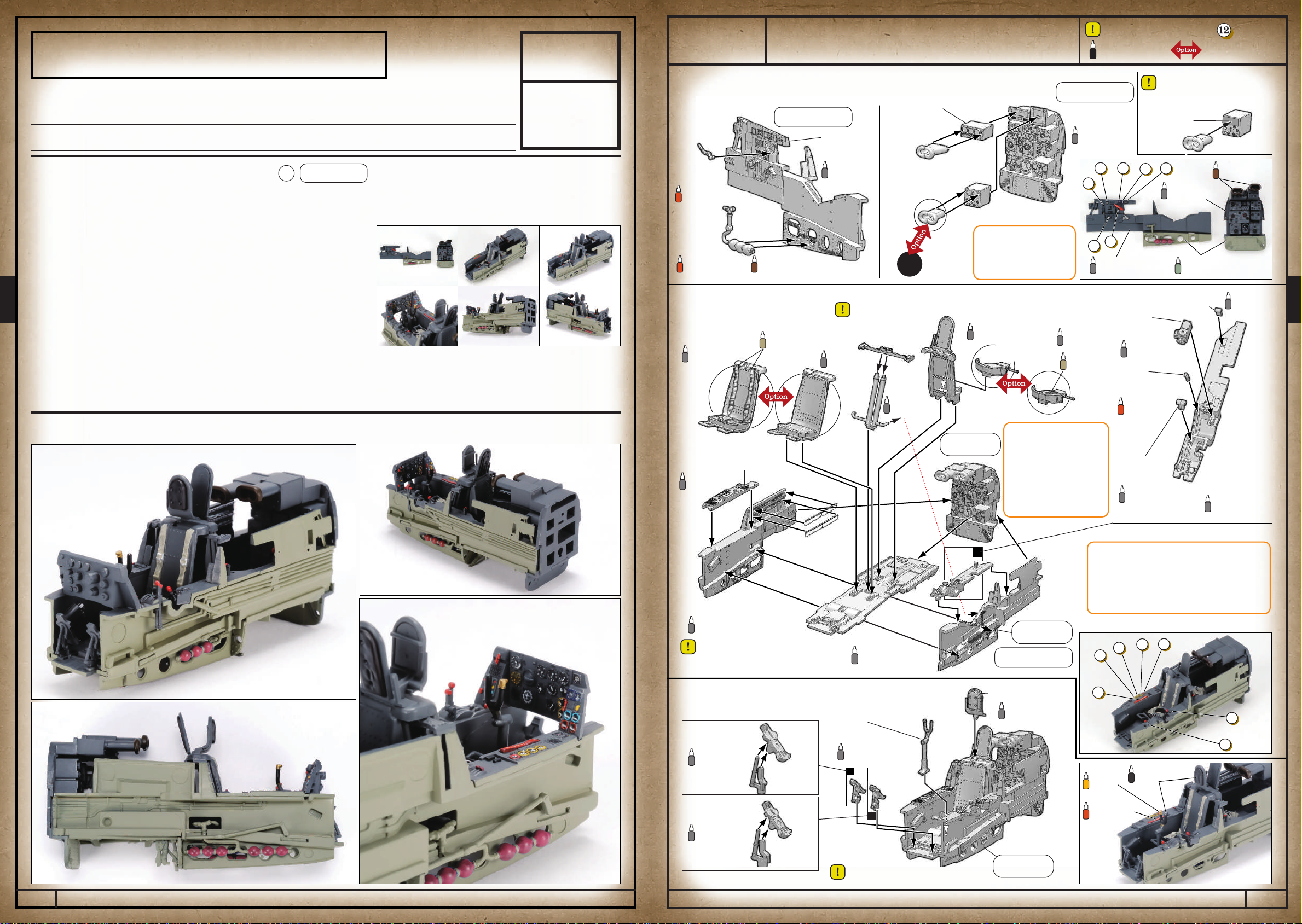
-2. Cockpit
-3. Rumpf
-4. Flügel
-5. Rumpf und Flügel
-6. Hauptfahrwerk
-7. Letzte Ausrüstung
Färbung und Abziehbild
Teileliste
3.
4.
7.
12.
15.
23.
28.
31.
34.
42.
46.
Teil 1
Teil 2
Teil 3
Teil 4
Teil 5
Actual Aircraft Specifications / 実機 諸元
Assembly Information / 組み立てについて
Cockpit / コクピット
Engine / エンジン
Fuselage / 胴体
Main Wings / 主翼
Fuselage and Main Wings / 胴体と主翼
Landing Gear / 脚部
Final Outfitting / 最終艤装
Painting and Decals / 塗装とデカール
Parts List / パーツリスト
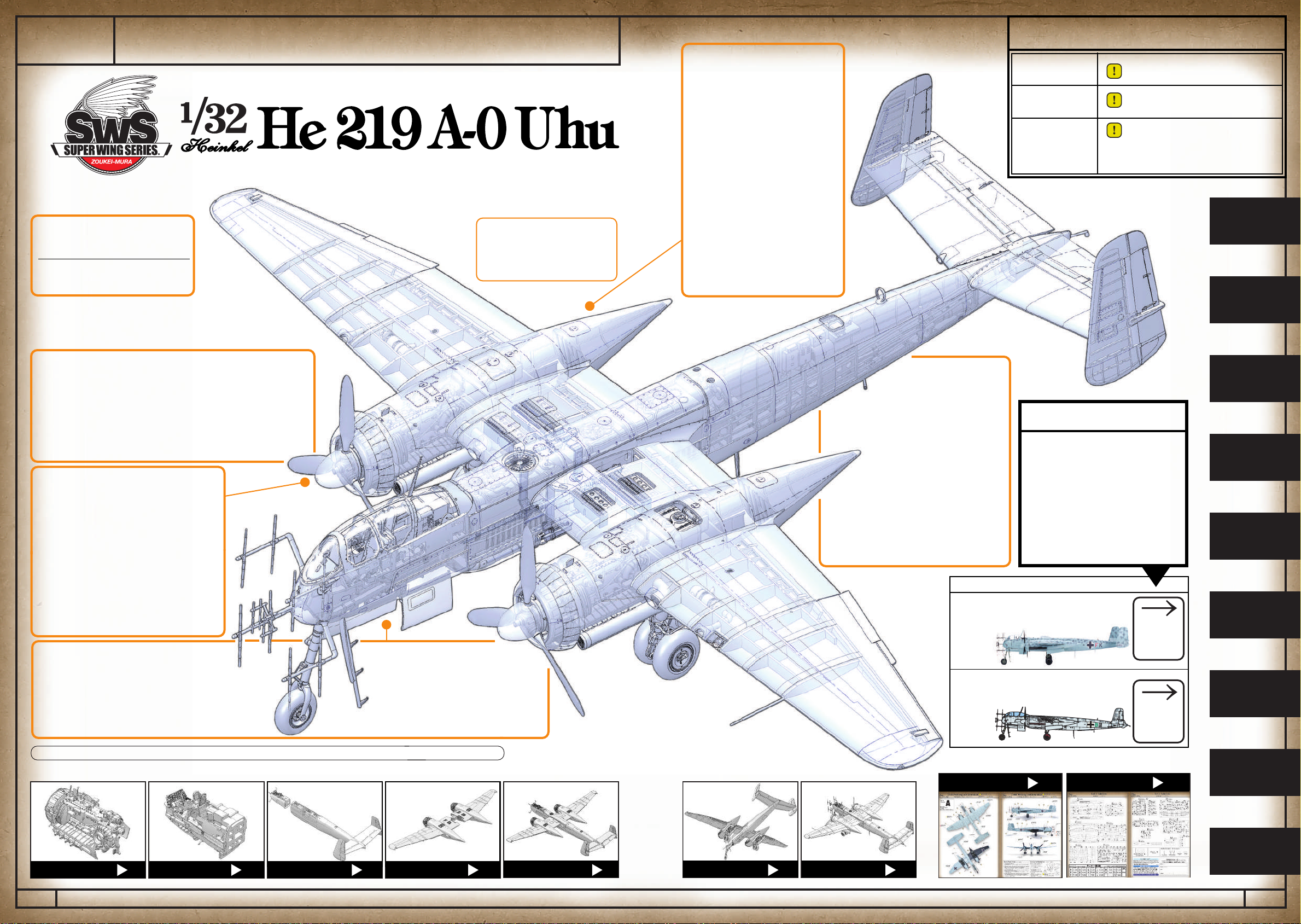
SWS No.6 - 1/32 He 219 A-0 Uhu
2. ZOUKEI-MURA INC. PRESENTS SUPER WING SERIES®No.6 1/32 HEINKEL He 219 A-0 Uhu
© ZOUKEI-MURA INC. All Rights reserved.
1 Actual Aircraft Specifications /実機 諸元
Teil 1 Eigentliches Flugzeug
1/32
HEINKEL
He 219 A-0 Uhu
3.
ZOUKEI-MURA INC. PRESENTS SUPER WING SERIES®No.6 1/32 HEINKEL He 219 A-0 Uhu
© ZOUKEI-MURA INC. All Rights reserved.