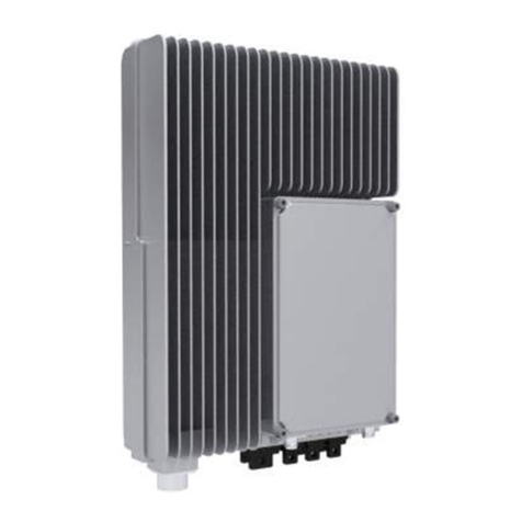
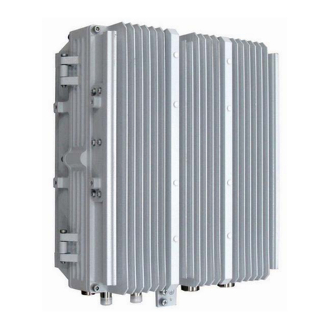
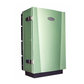
Zte ZXC10 CBTS O1 User manual

ZXC10 CBTS
CDMA2000Compact BaseTransceiver
Station
InstallationManual
ZTE CORPORATION
ZTE Plaza, Keji Road South,
Hi-Tech Industrial Par ,
Nanshan District, Shenzhen,
P. R. China
518057
Tel: (86) 755 26771900 800-9830-9830
Fax: (86) 755 26772236
URL: http://support.zte.com.cn
E-mail: doc@zte.com.cn

LEGAL INFORMATION
Copyright © 2005 ZTE CORPORATION.
The contents of this document are protected by copyright laws and international treaties. Any reproduction or distribution of
this document or any portion of this document, in any form by any means, without the prior written consent of ZTE
CORPORATION is prohibited. Additionally, the contents of this document are protected by contractual confidentiality
obligations.
All company, brand and product names are trade or service mar s, or registered trade or service mar s, of ZTE
CORPORATION or of their respective owners.
This document is provided “as is”, and all express, implied, or statutory warranties, representations or conditions are
disclaimed, including without limitation any implied warranty of merchantability, fitness for a particular purpose, title or non-
infringement. ZTE CORPORATION and its licensors shall not be liable for damages resulting from the use of or reliance on
the information contained herein.
ZTE CORPORATION or its licensors may have current or pending intellectual property rights or applications covering the
subject matter of this document. Except as expressly provided in any written license between ZTE CORPORATION and its
licensee, the user of this document shall not acquire any license to the subject matter herein.
The contents of this document and all policies of ZTE CORPORATION, including without limitation policies related to support
or training are subject to change without notice.
Revision History
Date Revision No.
Serial No. Description
04/04/2006
R1.0 sjzl20060563 CDMA2000 Compact Base Transcei er Station - English
Contents

ZTE CORPORATION
Values Your Comments & Suggestions!
Your opinion is of great value and will help us improve the quality of our
product documentation and offer better services to our customers.
Please fax to: (86 755-26772236; or mail to Publications R&D
Department, ZTE CORPORATION, ZTE Plaza, A Wing, Keji Road South,
Hi-Tech Industrial Park, Shenzhen, P. R. China 518057.
Thank you for your cooperation!
Document
Name ZXC10 CBTS CDMA2000 Compact Base Transcei er Station Installation Manual
Product
Version Document
Re ision Number
Equipment Installation Date
Presentation:
(Introductions, Procedures, Illustrations, Completeness, Le el of Detail, Organization,
Appearance)
Good
Fair
A erage
Poor
Bad
N/A
Accessibility:
(Contents, Index, Headings, Numbering, Glossary)
Good
Fair
A erage
Poor
Bad
N/A
Your e aluation
of this
documentation
Intelligibility:
(Language, Vocabulary, Readability & Clarity, Technical Accuracy, Content)
Good
Fair
A erage
Poor
Bad
N/A
Your
suggestions for
impro ement
of this
documentation
Please check the suggestions which you feel can i prove this docu entation:
Impro e the o er iew/introduction
Make it more concise/brief
Impro e the Contents
Add more step-by-step procedures/tutorials
Impro e the organization
Add more troubleshooting information
Include more figures
Make it less technical
Add more examples
Add more/better quick reference aids
Add more detail
Impro e the index
Other suggestions
___________________________________________________________________________
___________________________________________________________________________
___________________________________________________________________________
___________________________________________________________________________
___________________________________________________________________________
# Please feel free to write any comments on an attached sheet.
If you wish to be contacted regarding your co ents, please co plete the following:
Name Company
Postcode Address
Telephone E-mail

This page is intentionally blank.

Contents
About this Manual ...................................................................................xi
Purpose of this Manual ...........................................................................................xi
Typographical Conventions.....................................................................................xi
Mouse Operation Conventions................................................................................ xii
Safety Signs.........................................................................................................xiii
How to Get in Touch............................................................................................. xiv
Customer Support..............................................................................................................xiv
Documentation Support......................................................................................................xiv
Chapter 1.................................................................................... 15
Installation Preparation.........................................................................15
Hardware Installation low.....................................................................................16
CBTS Installation Precautions.................................................................................17
Environment Inspections .......................................................................................17
Installation Location Specifications.......................................................................................17
Temperature and Humidity Range .......................................................................................17
ower Supply Requirements................................................................................................18
Electromagnetic Radiation rotection....................................................................................18
Antenna Feeder System Requirements.................................................................................18
Other Accessory Devices.....................................................................................................19
Tool and Meter List for Installation..........................................................................19
Technical Documentation Preparation.....................................................................21
roject Commissioning Documents ......................................................................................21
Acceptance Reports ............................................................................................................21
Reference Documents.........................................................................................................21
Chapter 2.................................................................................... 23
Unpacking and Handover.......................................................................23
Checking Equipment List .......................................................................................24
Unpacking Wooden Box.........................................................................................25
Unpacking rocedure..........................................................................................................25
Checking Cabinet................................................................................................................26
Unpacking Carton .................................................................................................26
Carton Structure.................................................................................................................26

Unpacking rocedure..........................................................................................................26
Unpacking recautions........................................................................................................27
Checking Boards.................................................................................................................27
Acceptance and Handover .....................................................................................27
Chapter 3.................................................................................... 29
abinet Installation................................................................................29
Cabinet Structure..................................................................................................30
Cabinet Installation Precautions..............................................................................31
Installation Location Specification...........................................................................31
Cabinet Installation Modes.....................................................................................32
Direct Installation Mode.........................................................................................33
Direct Installation Mode Flow...............................................................................................33
Direct Installation Mode rocedure.......................................................................................34
Adjustable Base Installation Mode ..........................................................................39
Adjustable Base Structure...................................................................................................40
Adjustable Base Installation Mode Flow ................................................................................41
Adjustable Base Installation rocedure.................................................................................42
Cabinet Accessories Installation ...........................................................................................48
Cabling Runway .................................................................................................................48
CBTS Cabinet Interfaces........................................................................................49
ower Interface..................................................................................................................50
Feeder Cable Interface........................................................................................................50
E1/T1 Interfaces.................................................................................................................51
FE Interfaces......................................................................................................................51
Room Monitoring Interface..................................................................................................52
Order Wire hone Interface.................................................................................................52
ower Monitoring Interface..................................................................................................53
External BDS Interface........................................................................................................53
External Monitoring Interface...............................................................................................54
G S Interface.....................................................................................................................54
Chapter 4.................................................................................... 55
able Installation ...................................................................................55
Power and Grounding Cables .................................................................................56
ower Cable Types .............................................................................................................56
ower Cable reparation.....................................................................................................56
ower and Grounding Cable Connections..............................................................................57
Cable Installation Requirements...........................................................................................58
Trunk Cable Installation.........................................................................................60
T1 Cable Installation...........................................................................................................60
E1 Cable Installation...........................................................................................................61
Trunk Cable rocessing.......................................................................................................64
Trunk Cable Conversion......................................................................................................66
E1/T1 Cable Installation Requirements.................................................................................68
Feeder cable installation......................................................................................................69
Chapter 5.................................................................................... 71
Monitoring System Installation..............................................................71
Smog Sensor Installation.......................................................................................72
Installation rocedure.........................................................................................................72
Terminal Connections .........................................................................................................73
Temperature and Humidity Sensor Installation........................................................73
Installation rocedure.........................................................................................................73
Terminal Connections .........................................................................................................75
Installation recautions.......................................................................................................75
Infrared Sensor Installation....................................................................................75
External Monitoring Cable Installation.....................................................................77
Chapter 6.................................................................................... 79
Main Antenna Feeder System Installation.............................................79
Main Antenna System Installation ..........................................................................80
Antenna Installation reparation..........................................................................................80
Antenna Installation recautions..........................................................................................80
Main Antenna Feeder System Structure................................................................................80
Antenna Installation Technical arameters............................................................................82
Antenna Installation Flow Chart ...........................................................................................83
Selecting Installation osition...............................................................................................83
Moving and Hoisting Antenna ..............................................................................................83
Uni-Directional Antenna Installation .....................................................................................85
Omni-Directional Antenna Installation..................................................................................87
Main eeder Installation.........................................................................................88
Feeder Window Installation .................................................................................................89
Feeder Connector reparation..............................................................................................90
Feeder Cutting ...................................................................................................................93
Jumper Installation.............................................................................................................93
Waterproofing Joints...........................................................................................................94
Feeder Grounding Clip Installation........................................................................................95
Routing Feeders .................................................................................................................96
Hoisting Feeders to Tower...................................................................................................97
CBTS Grounding System.....................................................................................................99
Grounding rinciples .........................................................................................................100
Grounding Copper Busbar Installation................................................................................100
Lightning Arrester Installation............................................................................................101

Routing Feeders into Equipment Room...............................................................................102
Chapter 7.................................................................................. 105
GPS Antenna Feeder System Installation............................................105
GPS Antenna eeder System Structure.................................................................106
Installation Position and Requirements..................................................................107
Installation Requirements..................................................................................................108
Lightning rotection Requirements.....................................................................................109
NJ-9 Connector Preparation.................................................................................109
NJ-9 Connector ................................................................................................................109
Connector reparation rocedure.......................................................................................110
G S Connector Installation check.......................................................................................115
Chapter 8.................................................................................. 117
Board Installation.................................................................................117
Installation low Chart.........................................................................................118
Installation Procedure and Precautions..................................................................119
CTSB Board Slot...............................................................................................................119
RFS Board Installation....................................................................................................... 120
BDS Board Installation......................................................................................................121
Installation recautions.....................................................................................................122
Chapter 9.................................................................................. 123
Hardware Installation heck ...............................................................123
Cabinet Installation Check ...................................................................................124
Cabling Rack Installation Check............................................................................124
Cable Installation Check ......................................................................................125
ower and Grounding Cables.............................................................................................125
Trunk and RF Cables.........................................................................................................126
Board and Sensor Installation Check.....................................................................126
Antenna and GPS eeder System Installation Check ..............................................127
1/2” Indoor Jumper..........................................................................................................127
Lightning arrester.............................................................................................................127
Main G S Feeder..............................................................................................................127
Feeder Window and Waterproof Curve............................................................................... 128
Three – Way Feeder Clamp...............................................................................................128
1/2” Outdoor Jumper........................................................................................................129
Antenna...........................................................................................................................129
Feeder SWR.....................................................................................................................130
Environment Check.............................................................................................130
Chapter 10................................................................................ 131
Power On and Off Mechanism..............................................................131

Power Supply Inspection .....................................................................................132
Power-on Procedure............................................................................................133
First Time ower-on.......................................................................................................... 133
Normal ower-on .............................................................................................................133
Power-off Procedure............................................................................................133
Appendix A ............................................................................... 135
Packing, Storage and Transportation ..................................................135
Packaging ..........................................................................................................136
Cabinet packing................................................................................................................136
Cabinet acking rocedure ................................................................................................137
Board acking..................................................................................................................139
Board packing procedure...................................................................................................139
Base acking.................................................................................................................... 144
Engineering Materials acking............................................................................................144
Transportation....................................................................................................144
Storage..............................................................................................................145
Appendix B ............................................................................... 147
SiteMaster Usage..................................................................................147
requency Range Selection..................................................................................148
SiteMaster Check................................................................................................148
eeder Input Parameters.....................................................................................148
Tester Installation...............................................................................................149
Measuring SWR ..................................................................................................149
Measuring DT ...................................................................................................150
Appendix C ............................................................................... 151
abinet Working Modes .......................................................................151
Appendix D............................................................................... 153
Monitoring ables Definition................................................................153
Acronyms.................................................................................. 157
igures...................................................................................... 159
Tables ....................................................................................... 163
Index ........................................................................................ 165

This page is intentionally blank.

Confidential and Proprietary Information of ZTE CORPORATION
xi
About this Manual
Purpose of this Manual
This manual describes ZXC10 Compact Base Transceiver Station
hardware installation.
Typographical Conventions
ZTE documents employ the following typographical conventions.
TABLE 1-TYPO GR AP HICAL CONVEN TIONS
Typeface Meaning
Italics
References to other guides and documents.
“Quotes” Links on screens.
Bold
Menus, menu options, input fields, radio button names, check
boxes, drop-down lists, dialog box names, window names
Bold
, with first
, with first , with first
, with first
letter capitalized
letter capitalizedletter capitalized
letter capitalized
Keys on the keyboard and buttons on screens
Constant width
Text that you type, program code, files and directory names,
and function names
[ ] Optional parameters
{ }
Mandatory parameters
| Select one of the parameters that are delimited by it
Note: Pro ides additional information about a certain topic.
Checkpoint: Indicates that a particular step needs to be checked
before proceeding further.
Tip: Indicates a suggestion or hint to make things easier or
more producti e for the reader.

ZXC10 CBTS I2 Installation Manual
xii
Confidential and Proprietary Information of ZTE CORPORATION
Mouse Operation Conventions
TABLE 2-MOUS E OPERATION CONVEN TION S
Typeface Meaning
Click Refers to clicking the primary mouse button (usually the left
mouse button) once.
Double-click Refers to quickly clicking the primary mouse button (usually the
left mouse button) twice.
Right-click Refers to clicking the secondary mouse button (usually the right
mouse button) once.
Drag Refers to pressing and holding a mouse button and mo ing the
mouse.

About this Manual
Confidential and Proprietary Information of ZTE CORPORATION
xiii
Safety Signs
TABLE 3-SAFE TY SIGN S
Safety Signs Meaning
Danger: Indicates an imminently hazardous situation, which if
not a oided, will result in death or serious injury. This signal
word should be limited to only extreme situations.
Warning: Indicates a potentially hazardous situation, which if
not a oided, could result in death or serious injury.
Caution: Indicates a potentially hazardous situation, which if not
a oided, could result in minor or moderate injury. It may also
be used to alert against unsafe practices.
Note: Indicates a potentially hazardous situation, which if not
a oided, could result in injuries, equipment damage or
interruption of ser ices.
Erosion: Beware of erosion.
Electric shock: There is a risk of electric shock.
Electrostatic: The de ice may be sensiti e to static electricity.
Microwa e: Beware of strong electromagnetic field.
Laser: Beware of strong laser beam.
No flammables: No flammables can be stored.
No touching: Do not touch.
No smoking: Smoking is forbidden.

ZXC10 CBTS I2 Installation Manual
xiv
Confidential and Proprietary Information of ZTE CORPORATION
How to Get in Touch
The following section provides information on how to obtain support for
the documentation and the software.
Customer Support
If you have problems, questions, comments, or suggestions regarding
your product, contact us by e-mail at support@zte.com.cn. You can also
call our customer support center at (86 755 26771900 and (86 800-
9830-9830.
Documentation Support
ZTE welcomes your comments and suggestions on the quality and
usefulness of this document. For further questions, comments, or
suggestions on the documentation, you can contact us by e-mail at
doc@zte.com.cn; or you can fax your comments and suggestions to (86
755 26772236. You can also explore our website at
http://support.zte.com.cn, which contains various interesting subjects like
documentation, knowledge base, forum and service request.
FCC STATEMENT
Before using this CDMA ZXC10 CBTS I28A and CBTS I219, read this
important RF energy awareness and control information and operational
instructions to ensure compliance with the FCC RF exposure guidelines.
NOTICE: Working with the equipment while in operation, may expose the
technician to RF electromagnetic fields that exceed FCC rules for human
exposure. Visit the FCC website at www.fcc.gov/oet/rfsafety to learn more
about the effects of exposure to RF electromagnetic fields.
Changes or modifications to this unit not expressly approved by the party
responsible for compliance will void the user’s authority to operate the
equipment. Any change to the equipment will void FCC grant.
This equipment has been tested and found to comply with the limits for a
Class A digital device, pursuant to the FCC Rules. This equipment
generates, uses and can radiate radio frequency energy and, if not
installed and used in accordance with the instructions, may cause harmful
interference to radio communications. However, there is no guarantee that
interference will not occur in a particular installation.

Confidential and Proprietary Information of ZTE CORPORATION
15
C ha p t e r 1
Installation Preparation
This chapter describes:
Hardware installation flow
CBTS installation precautions
Environment inspections
Installation location specifications
Temperature and humidity requirements
Power supply requirements
Electromagnetic radiation protection
Antenna feeder system requirements
Other accessory devices
Tool and meter list for installation
Technical documentation preparation
Project commissioning documents
Acceptance reports
Reference documents

ZXC10 CBTS I2 Installation Manual
16
Confidential and Proprietary Information of ZTE CORPORATION
Hardware Installation Flow
Figure 1 shows ZXC10 Compact Base Transceiver Station (CBTS hardware
installation flow.
FIGURE 1-HAR DW ARE INS TALLATI ON FLOW

Confidential and Proprietary Information of ZTE CORPORATION
17
CBTS Installation Precautions
Take following precautions during CBTS installation.
Avoid hot swap during board installation.
Never install antenna feeder system in case of lightning.
Check that lightening arresters are in proper contact. Replace damaged
arresters immediately.
Environment Inspections
Before installation, the operator should finalize and prepare installation
location, arrange power supply and grounding cables, and provide
necessary facilities for installation.
Installation Location Specifications
Installation location must fulfill the engineering requirements. Table 4 lists
equipment room basic requirements.
TABLE 4-INSTALL ATION LOCATION SPECIFI CATIONS
Ite Require ents
Space Keep an extra space for future expansion
Doors and
windows Ensure doors and windows are dust proof
Floor bearing Keep floor bearing capacity greater than 450 kg/m
2
Air conditioning
Ensure air-conditioning facilities are a ailable to maintain required
temperature and humidity
Anti-seismic
design Design equipment room to o ercome anti-seismic factor
Grounding Install lightning arrester and proper grounding equipment to a oid any
damage due to short circuits
Temperature and Humidity Range
Table 5 shows CBTS temperature and humidity range.
TABLE 5-TEMP ER ATURE AN D HUMIDITY RANGE
Ite Working range Reco ended range
Temperature -5
°
C ~ +45
°
C +15
°
C ~ +35
°
C
Humidity 15% RH ~ 93% RH 40% RH ~ 60% RH

ZXC10 CBTS I2 Installation Manual
18
Confidential and Proprietary Information of ZTE CORPORATION
Power Supply Requirements
Table 6 illustrates ZXC10 CBTS power supply requirements under normal
operation.
TABLE 6-POWE R SUPPLY INDICE S
Indices Na e Index Require ents
Power system
range -48 V power supply in range of -43.2 V ~ -56.5 V
Power noise le el
Satisfies Ministry of Post and Telecom technical
specifications
DC power
supply
Power protection
Includes O er- oltage/O er-current protection and
indication
110 V power supply in range of 85 V ~ 135 V
Power system
range 220 V power supply in range of 150 V ~ 300 V
Power noise le el
Satisfies Ministry of Post and Telecom technical
specifications
AC power
supply
Power protection
Includes O er- oltage/O er-current protection and
indication
Electromagnetic Radiation Protection
Table 7 shows electromagnetic radiation protection requirements.
TABLE 7-RADI ATIO N PROTECTI ON REQU IREM ENTS
Ite Require ents
Public exposure
In 24 hours of a day, a erage alue of electromagnetic power density
(in six consecuti e minutes) should be less than 0.4 W/m
2
(30 MHz ~
3000 MHz)
Professional
radiation
In 8 hours of a day, a erage alue of electromagnetic power density (in
six consecuti e minutes) should be less than 2 W/m
2
(30 MHz ~ 3000
MHz)
Antenna Feeder System Requirements
Check whether following items comply with CBTS requirements and
project design.
Height and dimensions of feeder window
Height, weight bearing and grounding of outdoor cable rack
Height, weight bearing and grounding of indoor cable rack
Height, diameter, weight bearing, wind resisting, grounding, lightning
protection, and direction of antenna installation pole of building BS
Height, diameter, weight bearing, wind resisting, grounding, lightning
protection, and direction of antenna installation pole of iron tower BS

Confidential and Proprietary Information of ZTE CORPORATION
19
Other Accessory Devices
According to requirements in the contract, check whether following items
are available:
Cables for external power supply and cabinet
E1 cable connecting CBTS and BSC
Fire extinguisher
Tool and Meter List for Installation
Table 8 shows tools and meters list required during installation.
TABLE 8-TOOL AND METER LIST
Category Na e
Special-purpose tools
One feeder connector knife
One wire stripper for 75 Ω coaxial cables
One crimping pliers for 75 Ω coaxial cables
One multi-functional crimping pliers
One multimeter
One SiteMaster VSWR tester
Earth resistance tester
Concrete drilling tools
One electric percussion drill
Auxiliary and sample bits
One acuum cleaner
Power socket (two-phase and three-phase socket, with current
capacity greater than 15 A)
General-purpose tools
Cross screwdri ers (4”, 6” and 8” each)
Flathead screwdri ers (4”, 6” and 8” each)
Adjustable wrenches (6’, 8’, 10’ and 12’)
Dual-purpose spanners (17” and 19” each)
One set of socket wrench
11.02 lb (5 kg) nail hammer
One 300 W iron
One 40 W iron
Solder wires

ZXC10 CBTS I2 Installation Manual
20
Confidential and Proprietary Information of ZTE CORPORATION
Category Na e
Measurement tools
One 50 m tape measure
One 5 m steel tape
One 400 mm le el bar
One angle meter
One compass
Plumb
Protection tools
Antistatic wrist strap
Safety helmet
Pair of glo es
Small tools
One hacksaw (with se eral saw blades)
One pair of sharp-nose pliers (8”)
One pair of diagonal pliers (8”)
One pair of slip joint pliers (8")
One pair of ices (8”)
One needle file set (medium sized)
Tweezers
One paintbrush
One pair of scissors
One hot blower
One solder sucker
One pair of hydraulic pliers
Crowbar
Auxiliary tools
Pulley block
Rope
Ladder
Forklift
Meter
Spectrum analyzer
SITE MASTER BS tester
Qualcomm test MS
Compass
Multimeter
Field strength tester
Note:
Do not use meters unless they are strictly calibrated and proven qualified.
Other manuals for ZXC10 CBTS O1
2
Table of contents
Other Zte Accessories manuals

Zte
Zte AT&T Wireless Home Phone Base User manual

Zte
Zte ZXSDR BS8800 C200 User manual

Zte
Zte ZXMBW E9200 User manual

Zte
Zte Consumer Cellular WF723 User manual

Zte
Zte Z723EL User manual

Zte
Zte ZXG10-BS30 User manual

Zte
Zte ZXSDR BS8900A GU360 Manual

Zte
Zte ZXSDR R8978 User manual

Zte
Zte ZXG10 BS21 User manual

Zte
Zte RSU82 S1900 Manual

Zte
Zte ZXG10-OB06 User manual

Zte
Zte ZXSDR BS8908 G060 User manual

Zte
Zte ZXSDR BS8800 User manual

Zte
Zte ZXSDR R8882 Technical specifications

Zte
Zte ZXC BTSB I28A User manual

Zte
Zte ZXMBW E9230 User manual

Zte
Zte ZXG10 OB06 User manual

Zte
Zte ZXC10 CBTS O1 User manual

Zte
Zte ZXSDR R8881 S4200 User manual

Zte
Zte ZXSDR R8882 L268 User manual