Note: When you pull the throttle from neutral position to full throttle position, the Blue LED will blink, and the blink frequency will go faster when the throttlegoes higher.
2. When some protection is activated
The RED LED is always on solid once the power button is pressed.
The RED LED blinks, single flash between every one second. Repeat like “¤ ¤ ¤” indicates that the voltage is abnormal.
The RED LED blinks, double flash between every one second. Repeat like “¤¤ ¤¤ ¤¤” indicates that the temperature is abnormal.
The RED LED blinks, single and double flash alternately between every one second. Repeat like “¤ ¤¤ ¤ ¤¤ ¤ ¤¤” indicates that both of the voltage and temperature is abnormal at the same time.
The RED LED will not have any responds even the voltage or temperature is abnormal if not detect the signal.
The BLUE LED blinks,double flash between every two seconds. Repeat like “¤¤ ¤¤ ¤¤” indicates that the throttle is abnormal.
(No throttle, or the throttle is not on the neutral position)
Throttle Signal
1. The ESC can support the 450Hz maximum PPM throttle signal.
2. The ESC throttle protection will be activated under the following situation, and the BLUE LED blinks double flash:
The throttle trigger do not place on the neutral position when the ESC turns on.
Lost the throttle signal.
3. If the ESC lost throttle signal during the operation, the BLUE LED will blink double flash, and the ESC will start to work again until the throttle signal is back to normal.
Sensored & Sensorless
1. The sensored mode is activated once the ESC detected the hall sensor signal at any time.
2. The ESC will work on sensorless mode once the ESC didn’t detect the hall sensor signal at any time.
3. The ESC will have a slight power drop and restored soon during the moment of sensored and sensorless mode switching.
4. The PWM driving frequency will be selected automatically by the ESC on sensorless mode, and the manual setting is invalid.
5. It is invalid to set the brake PMW frequency less than 1KHz and forced recognized as 1KHZ, if the ESC is on sensorless mode.
6. Boost and turbo functions are not available on sensorless mode.
Boost & Turbo
1. After the boost or turbo timing triggered, the RPM and current will be increased, and the battery/ESC/motor will be heating, so setting the proper timing and timing increased rate, and control
the time of timing will effect the battery/ESC/motor service life.
2. The difference of the Boost and Turbo Timing:
The Boost timing will be triggered even though you do not pull the throttle trigger to the full throttle position.
The Turbo timing will be triggered only when you pull the throttle trigger to the full throttle position.
3. The Boost timing plus the Turbo timing is equal to the final opened timing when the throttle reaches its maximum position, and the final total timing is 60 degree(for Beast Pro 150A total
timing is 15 degree). For example: If Boost timing set at 45 degree, and Turbo Timing set at 50 degree, so when the throttle reaches its maximum position, the Boost timing will be 45 degree,
and Turbo Timing only can be opened at 15 degree.
4. If set the low voltage or over temperature protection, and the protection is activated, then all the timing will be closed.
Series ESC User Manual
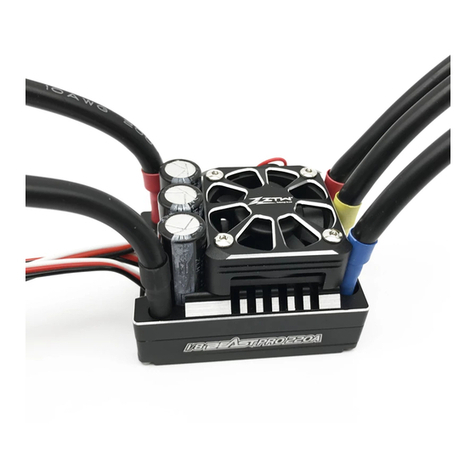
Thank you for your purchasing the ZTW product, the Beast Pro G2 Series ESC is our new generation of high performance sensored brushless electronic speed controller (competition version).
The high power systems for RC models can be very dangerous, we strongly suggest that you read this manual carefully before using your speed control. ZTW Model have no control over the use,
installation, application, or maintenance of these products, thus no liability shall be assumed nor accepted for any damages, losses of costsresulting from the use of this item.
Caution
Do not let children use this product without the supervision of an adult.
The ESC might get hot during use, be careful when handling it.
When soldering input/output wires and connections, set the iron to 60W minimum.
Always disconnect the battery after use, do not store with the battery connected.
Do not use near flammable materials.
If the ESC overheats, emits smokes or burns, immediately discontinue use, disconnect the battery and seek assistance.
Features
Full aluminum case and heat sink design, with highly efficient heat dissipation system.
Plenty of adjustable parameters allows adjusting the settings for most of racing, such as Modified, stock, zero timing, drifting etc.
32-bit microprocessor can support more powerful processing capability and more accurate motor output.
Enhanced throttle response, excellent acceleration, linearity and drive ability.
Multiple protection features: Low voltage cut-off protection, over-heat protection and throttle signal loss protection.
Built-in Bluetooth allows programming the parameter settings and firmware upgrades via app (support real time programming,no need restart the esc).
Data logging for real-time maximum ESC temperature, motor RPM, Voltage and Adv. Timing and so on.
Battery Wire Connection
When connecting the battery, pay attention to polarity: incorrect connection will damage the ESC and Battery.
As shown in the figure above, connect the positive (+) wire is connected to (+) battery port, and the negative (-) wire is connected to the (-) battery port.
Motor Wire Connection
1. Sensored Mode :
When using a sensored brushless motor, the three A/B/C ESC wires must connect to the three A/B/C motor wires correspondingly. It is necessary to connect the Sensor wire to the “Sensor”
socket on the ESC. Don’t change the wires sequence optionally.
2. Sensorless Mode:
When using a sensorelesss brushless motor, the #A, #B, #C wires of the ESC can be connected with the motor wires freely (without any sequence). If the motor runs in the opposite direction,
please swap any two wire connections.
Receiver Wire Connection
The signal wire supplies 6.0V to the receiver, servo, etc. So there is no need to connect an additional battery. External power connected to the receiver may
damage the ESC.
Black wire RX-
Red wire RX+6.0V
White wire RX-Signal
Reverse Mode: One shot & Two shot (In the Forward/Brake/Reverse Mode)
Product Name
Cont. Current
Burst Current
Input Voltage
BEC Output
Size(L*W*H)
Weight
ESC Programming Via
Firmware Upgrade
Waterproof
Car Applicable
160A
760A
2-3S Lipo
6.0V,7.4V/4A(Switch BEC)
37.0*38.2*31.5mm
96g
Mobile Phone APP
Supported
No
1/10 Touring Car/Buggy Racing
220A
1000A
2-4S Lipo
6.0V,7.4V/10A(Switch BEC)
55.2*40.2*36.5mm
155g
Mobile Phone APP
Supported
No
1/8th On-Road/Off-Road/Truggy Racing
Beast PRO Sensored 160A G2 Beast PRO Sensored 220A G2
150A
950A
2-6S Lipo
6.0V,7.4V/8A(Switch BEC)
55.0*48.0*37.5mm
165g
Mobile Phone APP
Supported
No
1/8th Trucks/Monster Trucks
Beast PRO Sensored 150A G2
Specification
Connection
Battery
Switch
Receiver
Sensor wire
ESC
Motor
Power On/Off ESC
1. Press the power button then the ESC will be powered on.
2. Press and holding the power button until the all LEDs died out, then the ESC will be powered off.
(Note: Please place the throttle trigger on the neutral position: within 10%, otherwise the ESC can not be powered off.)
Throttle Calibration
1. Connect the ESC with the battery and receiver well, then turn on the transmitter.
2. Press and holding the power button until the blue LED is on solid, the motor have a long beep at the same time, then release the power button, the red led will be on solid, the ESC enters to
the calibration mode.
3. Pull the throttle trigger to the full throttle position, the blue led blinks three times and the motor beeps once, the full throttle position is saved.
4. Push the throttle trigger to the full brake position, the blue led blinks three times and the motor beeps twice, the full brake position is saved.
5. Release the throttle trigger to the neutral position, the blue led blinks three times and the motor beeps three times, the throttle calibration is completed.
6. The ESC can support reverse throttle calibration, if the transmitter throttle set reverse (it means pull the throttle will go to 1000 throttle position/normally is 2000, and push the throttle will go
to 2000 throttle position/normally is 1000), then you do the throttle calibration the same way as usual (as above), it will not have any effects on the ESC forward and revers way even if the
transmitter throttle set reverse.
Software Functions and Settings
Press and hold the power button
Pull the throttle trigger to the full
throttle position
Push the throttle trigger to the full
brake position
Release the throttle trigger to
neutral position
Blue LED blinks
three times,
motor one beep
Blue LED blinks
three times,
motor two beeps
Blue LED blinks
three times,
motor three beeps,
throttle calibration done
Until blue LED is on solid Release the power button The red LED is on solid
The ESC enters to the calibration mode
Remark: No need to restart the ESC again after throttle calibration finished.
Do not move the throttle during the time of the blue led blinks.
LED Status
1.During operation
Throttle Position
Neutral
Full Throttle
Full Brake
Blinking
ON
OFF
OFF
ON
ON
Blue LED Red LED
Real-time Data
1. The real-time data can be read only when the ESC have the throttle signal.
2. The real-time data is just a reference data with±10% accuracy, if you want to get the more accurate real-time data, you need to use the more professional equipment.
3. The description of the real-time data items:
Number
1
2
3
4
5
6
7
8
9
Input Throttle
Output Throttle
Voltage
Min. Voltage
Temperature
Max. Temperature
RPM
Max. RPM
Adv. Timing
The throttle from the Receiver to the ESC
The throttle from the ESC to the Motor
The battery voltage is being read by the ESC
The minimum voltage was read by the ESC
The ESC temperature
The maximum temperature was read by the ESC
Revolutions per minutes
The maximum RPM was read by the ESC
Advance Timing, The ESC total timing (Boost & Turbo)
Item Description
Protection
1. High Voltage Protection:
If the ESC detected the voltage too high(Higher than the esc standard voltage), when the ESC turns on, and the voltage protection was not set “OFF”, then the voltage protection will be
activated, and the maximum throttle output will be limited within 50%.(The high voltage protection only worked on the moment of the ESC turns on, and it will not work on the other stages
even it detected the high voltage, once the high voltage protection opened, even though the voltage comes down to the normal voltage, the protection will not be relieved.)
2. Low Voltage Protection:
If the ESC detected the voltage less than the set value at anytime, and this voltage keep for a while, then the low voltage protection is activated, and the maximum throttle output will be limited
within 50%.(Once the low voltage protection activated, even though the voltage comes back to normal, the protection can not be relieved.)
3. Thermal Protection:
The output throttle from the ESC will be limited (not over 50%) with the thermal value you have preset.(The Thermal protection will be dismissed when the ESC temperature drop to 65℃)
4. If the voltage protection and temperature protection set off, and when the voltage and temperature become abnormal, the LED status will indicates the problems correspondingly, but will not
limit the throttle output and will not close all ESC timing.
5. If some issues happen, cause ESC drive the motor failure, it will go into a protection; you will hear motor "beep beep beep" ,and it will stop beeping until release throttle to
neutral position at least 0.2s.
Bluetooth
1. Reset password: When the ESC turns on, press and holding the power button around 10 seconds, the ESC will restore the Bluetooth password to default setting 0000.
2. With ZTW Bluetooth, connected the ZTW app to the ESC, the user can program parameters, upgrade firmware and check the real-time data of the ESC on the APP.
3. Due to the range limit of Bluetooth, the operational distance is around 10 meters.(If there are many metals or other strong interference signals or obstacles around will short the operational
distance)
4. The Bluetooth name can not be changed.
5. The Bluetooth connecting will be failed during the ESC throttle calibration process.
Programmable Items
1. The user can program parameters at any status if the ESC turns on, and new programmed parameters will be took effect immediately, no need to restart the ESC, it means the programming
parameters can be competed online, so it can provide a very intuitive feeling between the before programming and after programming. There will be some impacts on the battery/ESC/motor
if you program some parameters when the motor in a high-speed rotation. For example, if you changed the motor rotation when the motor in a high-speed rotation, then the ESC will drive the
motor reverse immediately, but the motor can not be reverse immediately because of its inertia, then it will cause a big current and vibration. Or when the Boost or Turbo timing opened, but
you set it off when the motor in a high-speed rotation, it also will cause a big current, so we would like to recommend not programming parameters when the motor in a high-speed rotation.
2. The programming parameters are saved in the ESC embedded flash memory, and the flashed card have a limited programming life ( around 10K times), so don’t program the ESC very often.
Firmware Upgrade
1. If the ESC firmware upgrade failed during the upgrading process, please restart the ESC again, and must upgrade the ESC firmware via the APP again (all the other functions are not available),
the ESC will get right after the firmware upgraded successfully.
2. The Red Led will blink a faint light when the ESC in the firmware upgrade mode, and the Blue Led will blink a faint light when the ESC have data transmission.
3. Please do not turn off the ESC during the time of the ESC firmware upgrading process. ( And the ESC only can be switched off after pressing the power button around 5 seconds)
When the vehicle is moving forward Push the throttle trigger to
reverse/brake zone
Push the throttle trigger to
reverse/brake zone
The vehicle will reverse Return the throttle trigger
to neutral zone
One Shot
Less than two seconds
More than
two seconds
Two Shot
The vehicle will brake
Push the throttle trigger to
reverse/brake zone
The vehicle will brake again
Trouble Shooting
Trouble Shooting Possible causes Solutions
The ESC was unable to start the status LED, the motor,
and the cooling fan after it was powered on.
1. No power was supplied to the ESC.
2. The ESC switch was damaged.
1. Check if all ESC & battery connectors have been well soldered
or firmly connected.
2. Replace the broken switch.
The motor suddenly stopped or significantly reduced
the output in operation.
1. The receiver was influenced by some foreign interference.
2. The ESC entered the battery LVC (Low Voltage Cut off)
protection.
3. The ESC entered the thermal (over-heat) protection.
1. Check all devices and try to find out all possible causes, and
check the transmitter’s battery voltage.
2. The RED LED blinks, single flash between every one second.
3. The RED LED blinks, double flash between every one second.
The motor stuttered but couldn’t start. 1. Some soldering between the motor and the ESC was not good.
2. The ESC was damaged (some MOSFETs were burnt).
1. Check all soldering points, please re-solder if necessary.
2. Contact the distributor for repair or other customer services.
The car ran forward/backward slowly when the
throttle trigger was at the neutral position.
1. The neutral position on the transmitter was not stable, so
signals were not stable either.
2. The ESC calibration was not proper.
1. Replace your transmitter
2. Re-calibrate the throttle range or fine tune the neutral position
on the transmitter.
Shenzhen ZTW Model Science & Technology Co.,Ltd
ADD: 2/F, Block 1, GuanFeng Industrial Park, Jiuwei, Xixiang, Baoan, Shenzhen, China, 518126
TEL: +86 755 29120026, 29120036, 29120056 FAX: +86 755 29120016 WEB
SITE: www.ztwoem.com EMAIL:
[email protected]om
A
B
C
ABC
Programmable Items Description
SECTION PROGRAMMABLE ITEMS
THROTTLE
BRAKE
PROGRAMMABLE ITEMS DESCRIPTION
Throttle Response The shorter the time, the quicker the acceleration.
Coast With this function activated, the car won’t slow down immediately but coast for a while when reducing the throttle input.
Neutral Range
The wider the neutral range, the further the throttle trigger/stick must be moved away from the neutral point.
Otherwise, the car won’t move.
Min. Throttle The bigger the value, the more aggressive the start-up when moving the throttle trigger/stick away from the neutral range.
Minus The bigger the throttle minus value, the lower the car speed.
Minus Range It determines the throttle range within which the (Throttle) Minus function works. The bigger the
value, the wider the effective range.
Max. Forward force The lower the value, the slower the maximum speed in the Forward direction.
Max. Reverse force The lower the value, the slower the maximum speed in the Reverse direction.
Brake Response The shorter the time, the quicker the braking.
Min. Brake Force After entering the braking mode, the higher the value, the stronger the brake force when moving the throttle
trigger/stick away from the neutral range.
Max. Brake Force The lower the value, the weaker the maximum brake force.
Fwd. Drag Brake Force The brake force when the throttle trigger/stick is at the neutral position.
The lower the value, the further the coast.
Fwd. Drag Brake Response The shorter the time, the faster the braking in the forward direction.
Rev. Drag Brake Response The shorter the time, the faster the braking in the Reverse direction.
PWM Freq. The PWM frequency for braking.
BOOST
TURBO
GENERAL
Boost Timing With this function activated, the motor will be able to get a higher RPM.
Trigger It’s the way how Boost Timing is triggered, it can be triggered by throttle input or RMP.
Throttle Threshold The throttle threshold at which the Boost Timing will be triggered. The Boost Timing will be activated when the
Boost Triggering is set to “By Throttle” and the throttle input exceeds the threshold.
RPM Threshold The RPM threshold at which the Boost Timing will be triggered. The Boost Timing will be activated when
the Boost Triggering is set to “By RMP” and the motor RPM exceeds the RPM threshold.
Initial Angle It’s the timing value when the Boost Timing is initially activated. The higher the value, the more aggressive the power,
and the more difficult to control it.
Angle Inc. Rate The higher the value, the more aggressive the power, and the more difficult to control it.
Angle Dec. Rate The higher the value, the quicker the speed decrease. The effect, similar to braking, will be generated
when the speed is really high.
Turbo Timing It’s the timing activated when the throttle input reaches 100%.
Angle Inc. Rate The higher the value, the more aggressive the power, and the more difficult to control it.
Angle Dec. Rate The higher the value, the faster the speed decrease. The effect, similar to braking, will be generated
when the speed is really high.
Turbo Delay With this function activated, the Turbo Timing won’t be activated immediately after the throttle trigger/stick is
moved to the 100% position.
Delay Reload
It determines whether or not to delay and reload when the throttle trigger/stick is moved away and quickly
returned to the 100% point with the Turbo Timing is activated. There are two options: Wait
(reload after the turbo timing is decreased to 0), Instant (reload immediately when the throttle trigger/stick is
moved away from the 100% position).
Motor Rotation It’s the direction in which motor spins. With the factory default setting, it may run in the opposite direction in
some scenarios. This function allows users to switch the rotational direction if necessary.
Motor Poles It allows users to manually set the pole count of the motor, so to get the correct RPM threshold at which the Boost Timing
will be triggered. And users are able to check the actual motor RMP in the real-time data part of the mobile phone App.
Running Mode There are three running modes: Forward/Brake, Forward/Brake/Reverse, and Forward/Reverse.
Reverse Mode It’s only available when the running mode is set to Forward/Brake/Reverse. There are two options: One Shot
(pull the throttle trigger/stick once) & Two Shots (quickly pull the throttle trigger/stick twice).
Drive PWM Freq.
It’s the PWM frequency ESC used for driving motor. The lower the PWM driving frequency, the faster the acceleration, and
the worse the throttle linearity; the higher the PWM driving frequency, the smoother the throttle linearity, and it will result
in fast temperature increase.
CutOFF Voltage With it set to “Auto”, the ESC will automatically identify the number of LiPo cells you’ve plugged in
the moment it’s powered on.
CutOFF Thermal The ESC will automatically cease operation when the internal temperature rises above user-selectable values.
BEC Output Select the output of the Battery Eliminator Circuit depending on the operating voltage requirements of the servos.
Rev. Drag Brake Force The brake force when the throttle trigger/stick is at the neutral position. The lower the value, the further the coast.
A/C Swap It’s for switching the motor wires: A & C. When setting to “No”, the output wires at the ESC side will be connected to
the motor in the following sequence: A-A, B-B, and C-C; when setting to “Yes”, the wiring sequence will be: A-C, B-B, C-A.


